Method of producing roof panelling with an integrated lighting system and the panelling thus obtained
US20050122732A1
2005-06-09
10/484,938
2001-07-24
✅ Patent granted
US 7,234,850 B2
2007-06-26
WO; PCT/ES01/00294; 20010724
WO; WO03/010032; 20030206
Laura Tso
2021-10-13
Abstract:
The procedure consists in incorporating in the actual process of conforming a roof lining (13), determined by the securing to each other of a previously conformed lining support (3) and the positioning and securing thereon of a coating (11), of one or more electroluminescent strips (8) which will constitute a lighting system of the roof lining (13), which electroluminescent strips (8) are integrated between such lining support (3) and coating (11), each of them with a ribbon cable (10) and a connector which are made to pass through a hole (5) of the support (3) of the lining and is finished in a connector (9), which is hidden by the rear face of the actual lining for its connection to the power supply of the roof of the vehicle in which said lining (13) is applied.
Inventors:
- Darío SOTO ROMERO 2 🇪🇸 Burgos, Spain
- Angel Solanas Garcia 1 🇪🇸 Burgos, Spain
- Carolina Olivan Ahedo 1 🇪🇸 Burgos, Spain
Assignee:
- Grupo Antolin-Ingenieria, S.A. 10 🇪🇸 , Spain
Interested in similar patents?
Get notified when new applications in this technology area are published.
Classification:
B60R13/0212 » CPC main
Elements for body-finishing, identifying, or decorating; Arrangements or adaptations for advertising purposes; Trim mouldings Ledges; Wall liners for passenger compartments ; Roof liners Roof or head liners
B60Q3/745 » CPC further
Arrangement of lighting devices for vehicle interiors; Lighting devices specially adapted for vehicle interiors characterised by the purpose for overall compartment lighting; for overall compartment lighting in combination with specific lighting, e.g. room lamps with reading lamps using lighting panels or mats, e.g. electro-luminescent panels, LED mats
B60R13/0225 » CPC further
Elements for body-finishing, identifying, or decorating; Arrangements or adaptations for advertising purposes; Trim mouldings Ledges; Wall liners for passenger compartments ; Roof liners; Roof or head liners self supporting head liners
B29C51/08 » CPC further
Shaping by thermoforming, i.e. shaping sheets or sheet like preforms after heating , e.g. shaping sheets in matched moulds or by deep-drawing; Apparatus therefor Deep drawing or matched-mould forming, i.e. using mechanical means only
B29C51/12 » CPC further
Shaping by thermoforming, i.e. shaping sheets or sheet like preforms after heating , e.g. shaping sheets in matched moulds or by deep-drawing; Apparatus therefor of articles having inserts or reinforcements
B29C51/16 » CPC further
Shaping by thermoforming, i.e. shaping sheets or sheet like preforms after heating , e.g. shaping sheets in matched moulds or by deep-drawing; Apparatus therefor Lining or labelling
B29C2791/001 » CPC further
Shaping characteristics in general Shaping in several steps
B29L2031/3011 » CPC further
Other particular articles; Vehicles, e.g. ships or aircraft, or body parts thereof; Body finishings Roof linings
B29L2031/3061 » CPC further
Other particular articles; Vehicles, e.g. ships or aircraft, or body parts thereof; Cars Number plates
B60R2013/0287 » CPC further
Elements for body-finishing, identifying, or decorating; Arrangements or adaptations for advertising purposes; Trim mouldings Ledges; Wall liners for passenger compartments ; Roof liners integrating other functions or accessories
Description
OBJECT OF THE INVENTIONThe present invention relates to a procedure for obtaining a roof lining with integrated lighting system, the fundamental characteristic of which is that in the actual process of forming the lining, applicable with its coating on the roof of vehicles, it incorporates a lighting system based on electroluminescent light strips, defining a single assembly for its definitive installation on the roof of a vehicle without the necessity of having to mount the lighting system independently, since it is integrated in the lining itself.
The roof lining for vehicles is likewise an object of the invention, said lining being obtained by means of the procedure of the invention, which lining incorporates a lighting system constituted by one or several electroluminescent strips, each one of them with its corresponding ribbon cable and connector for the supply of electric power to said strip or strips and a connector for the connection to the general roof wiring system.
BACKGROUND OF THE INVENTIONAt the present time some roof linings are known which incorporate different accessories such as loudspeakers, head airbags, etc., their purpose being to increase the added value of the roof lining, incorporating therein different accessories which habitually constitute elements independent of the lining.
Regarding the accessories which constitute the interior lighting systems of a motor vehicle, they are presently constituted by assemblies of pieces independent of the roof lining, and they are mounted thereon in a different and subsequent phase to that of forming the lining.
Traditionally the mounting of these lighting systems was carried out in a stage different to that of mounting the roof lining, although at the present time alternatives exist in which modular roofs are marketed wherein the mounting of some components, like those for example associated with the lighting system of the interior of the vehicle, is carried out on the roof lining on the lining supplier's premises, whereby the modular assembly is subsequently mounted on the vehicle in a single step.
In any case, the assembly of pieces which form the interior lighting systems of vehicles, corresponds to a source of light emission; a diffuser element of the light emitted by said source; a supporting element for the assembly and a system of cables which feeds the light source with the necessary electric power.
These systems present a series of drawbacks among which the following can be pointed out:
-
- The traditional sources of light, emit heat to the consequent detriment of user comfort, as well as of the life of other components in the vehicle which can be mounted near to them.
- The traditional light sources produce very localized lighting producing areas of shadow inside the compartment, that is, they cannot be used as ambient lighting which produces a general illumination of the compartment without it being very harsh. Nor is it possible to resolve this problem of lighting by increasing the number of points of light, due to the aforementioned problem of heat emission.
- The light intensity cannot be varied, as a function of the quantity of external light or of the requirements at any given moment.
- The traditional lighting systems are on occasions a nuisance for the drivers of other vehicles.
- The traditional lighting systems, or at least the light diffusers remain visible at times when their operation is not required, which affects the development of the complete vehicle and the aesthetic function of the interior thereof.
- The traditional systems require space for their location and assembly, affecting the habitability of the interior of the vehicle.
The procedure proposed offers a solution which resolves at the same time the functions required of a roof lining and those required of a lighting system for the interior of the vehicle, the incorporation being obviated of components traditionally utilized in lighting systems, such as the light diffuser element, support elements for the light source, etc.
More specifically, the procedure of the invention is based on conforming the roof lining of a vehicle in such a way that in the same conformation procedure the corresponding lighting system is incorporated and integrated, the latter being determined by one or several electroluminescent strips, with the addition of a ribbon cable for the power supply to said strip or strips and a connector for connection to the general system of roof wiring.
The procedure is based on the following operative phases:
-
- Positioning of the different layers which will form the support of the roof lining on a press.
- Conformation by means of said press of the support and the implementation of a hole for the passage of the corresponding power supply ribbon cable. In this same phase, in correspondence with the corners of the support, a like number of holes are practiced which will serve for the centring and subsequent positioning of said support.
- Extraction of the lining support obtained in the above press and positioning thereof on a supporting cradle.
- Positioning and mounting of the electroluminescent strips on the support of the lining located in the supporting cradle. The securing of those electroluminescent strips on the surface of the lining support is carried out by application of adhesive, be this a two-sided adhesive tape previously fixed to the electroluminiscent strip, or by applying adhesive beforehand on the corresponding surface of the lining support in order to attach the strip on said adhesive.
- This operation can be completely manual or the system of positioning the electroluminescent strips can be automated. In the first case, a reference is necessary on the lining itself, like for example, an insert which is implemented in the previous conforming process. In the second case, the actual supporting cradle will serve as reference for the automatic positioning system.
- Positioning of the power supply ribbon cable, passing the corresponding connector and a part or end of said ribbon cable through the hole practiced for this purpose in the lining support, the end length of the ribbon cable and of the connector being arranged on the unseen face of the lining, to allow their subsequent connection to the wiring system of the roof. The aforementioned operation of positioning or assembly of the flat connector and of the ribbon cable, can be carried out by hand or automatically.
- Extraction of the roof lining with the electroluminiscent strips fixed thereto, with respect to the supporting cradle.
- Positioning of the lining support with the electroluminescent strips on a coating press.
- Location of the coating on the support or lining located on the press and performing the corresponding pressing action.
- Finally, cutting is carried out, both of the superfluous material of the perimeter, and of those holes necessary for housing other functions, obtaining in this way a roof lining which has the corresponding lighting system based on electroluminescent strips integrated therein, all capable of being mounted correctly on the roof of a vehicle and establishing the corresponding connection of the connector to the power source of the vehicle roof.
The lining obtained based on the aforementioned procedure is also an object of the invention, which lining is constituted, as is traditional, by means of a support and the corresponding coating thereof, with the configuration appropriate to the vehicle in which it is to be applied, but with the innovation of having integrated in an inseparable way the electroluminescent strip or strips which will constitute the lighting system of the roof lining.
The lining obtained offers a series of advantages with respect to those conventionally available, which can be summarized in the following:
-
- 1.—Reduction of the manufacturing costs, by performing the mounting of the lighting system in the same process of conforming the roof lining, with the consequent saving through elimination of the mounting and subsequent installation of the lighting system.
- 2.—Elimination of such components as the light diffuser or the support for the source of light emission required in the traditional lighting systems.
- 3.—The source of light emission does not produce heat, resulting in greater user comfort and therefore allowing a larger number of light sources distributed all over the roof.
- 4.—Possibility of producing a uniform light inside the compartment, minimizing the number of dark areas.
- 5.—The aesthetic aspect is enhanced both of the roof of the vehicle and of the compartment in general thereof, insofar as no element is visible when the lighting system is off.
To complete the description being made and with the object of assisting in a better understanding of the characteristics of the invention, in accordance with a preferred example of practical embodiment thereof, accompanying, as an integral part of said description, is a set of drawings wherein, by way of illustration and not restrictively, the following has been represented:
FIG. 1 shows a representation corresponding to the first four phases of the procedure for obtaining a roof lining for vehicles with integrated lighting system.
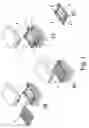
FIG. 2 shows three following phases of the actual process of obtaining the roof lining.
FIG. 3 shows the final phases of the procedure for obtaining the roof lining, all carried out in accordance with the object of the present invention.
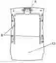
FIG. 4 shows a representation according to a general perspective of a roof lining obtained according to the procedure object of the present invention, and wherein can be seen an electroluminiscent strip as lighting system integrated in the lining itself.
FIG. 5 shows a plan view of the roof lining itself with the integrated lighting system formed by two electroluminescent strips arranged longitudinally, having eliminated from this lining the perimeter strips in which are practiced the corner holes for positioning of the support in the corresponding presses that act in certain phases of the procedure.
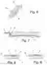
FIG. 6 shows a detail corresponding to the position of an electroluminiscent strip integrated in the lining, the detail corresponding to the section A-A of FIG. 4.
FIG. 7 shows another detail of the positioning and assembly of an electroluminiscent strip integrated in the roof lining obtained in accordance with the procedure of the present invention, this detail corresponding to the section represented by B-B of FIG. 4.
FIGS. 8 and 9 each show details in cross-section of how the electroluminescent strips can be mounted, it being seen in FIG. 8 how the strip is located on an insert of the lining support, whilst in FIG. 9 the strip is located on the lining support itself but without insert, superimposed instead on its surface.
PREFERRED EMBODIMENT OF THE INVENTIONBased on FIGS. 1 to 3, a description will be given of the procedure of obtaining roof linings with integrated lighting system, all in accordance with the object of the invention.
In a first phase, with reference (a), the different layers are arranged on a press (1) which will form the lining support (3), so that in a following phase indicated as (b), the pressing is carried out of those layers (2), the lining support (3) being obtained, as is shown in phase (c), wherein can now be seen the extraction of said lining support with respect to the press (1). In phase (b), as well as the conforming of the lining support (3), holes (4) are practiced, should they be necessary, in each of the corners of said lining support (3), as well as the practicing of one or several holes (5) for the passage of the respective connector and power supply cable. In the event that the subsequent positioning of the electroluminescent strips is done by hand, the support will be provided with inserts or marks which allow the operative to have a proper reference. In the event that the positioning of the strips is automatic, the holes (4) are foreseen to position the lining support (3) in an ensuing phase of the process. Those holes (4), although located in correspondence with the corners, belong to a perimeter strip which is removed from the lining support (3), in the final cutting operation once the coating of the same has been carried out.
In an ensuing phase (e), the lining support (3) with the holes (4) and (5) is located on a supporting cradle (6) which in the case of automatic positioning of the strips (8), will come with some nipples (7) serving as guide, for the lining support (3), by making the guide nipples (7) coincide with the holes (4) of the support (3). When the lining support (3) is positioned on the supporting cradle (6), as is represented in the detail corresponding to phase (f) of FIG. 2, the location and assembly of the electroluminescent strip or strips (8) is carried out on said support (3), automatically or by hand, employing in this latter case the reference inserts made on the lining support, said strips being fixed by means of an adhesive of any kind.
In this phase the flat connector (9), which is seen in FIG. 7, is made to pass through each of the holes (5) of the support (3), so that each of the parts of the ribbon cable (10) to which the flat connector (9) is joined, is located together with the latter on the unseen face of the lining support (3), to allow the subsequent connection thereof to the wiring system of the roof.
In the following phases shown in (h) and (i) in FIG. 3, the coating (11) is placed on the lining support (3), and all this on a new press (12). In that position, corresponding to phase (i) of FIG. 3, the pressing and corresponding securing is performed, after application of an adhesive to the coating (11) on the lining support (3), obtaining in this way the actual roof lining (13), that is that formed by the support (3) and the lining (11), being extracted from that press (12) as is represented in phase (j) of FIG. 3, that roof lining (13) incorporating the lighting system based on the electroluminescent strip or strips (8) with the cable (10) connected to them and the connector (9) for the connection to the corresponding roof power supply, whereby the assembly can be applied correctly to the roof of the/a vehicle without the requirement of having to carry out subsequent assemblies as occurs conventionally in the traditional lighting systems for vehicle roofs.
Finally, in FIGS. 8 and 9, it is shown how the electroluminescent strip or strips (8) can be located, either in an insert (14) of the actual support (3) of the lining, or on the surface thereof, that is, without inlaying.
Finally, it is mentioned that after the phase of securing the coating (11) on the support (3), the removal is performed of the perimeter strip of said support (3), in which strip the holes (4) are made, to obtain the definitive lining (13), as is represented in FIGS. 4 and 5.
Claims
1. Procedure for obtaining roof linings with integrated lighting system, which being foreseen to procure a roof lining applicable to vehicles, and which lining is constituted by the securing to each other of a lining support. (3) and a coating (11) thereof, is characterised in that it comprises the following operative phases:
Positioning in a press (1) of the different layers (2) by means of which the support will be obtained of the lining;
Pressing of those layers (2), practicing one or several holes (5), for the passage of the wiring corresponding to each of the electroluminescent strips and, optionally, when the positioning of the strips is carried out automatically, practicing of holes (4) in correspondence with each of the corners of the lining support (3);
Extraction of the lining support (3) obtained in the press (1), with the holes (5) and, optionally, with the holes (4);
Positioning of said lining support (3) on a supporting cradle (6), with guide nipples (7) which, when employing automatic assembly of the electroluminescent strips (8), are lodged in the holes (4) of the lining support (3);
Location or securing of one or more electroluminescent strips (8) on the lining support (3) placed on the supporting cradle.
Extraction of the lining support (3) with the electroluminescent strip or strips (8) from the supporting cradle (6);
Mounting of the lining support (3) with the electroluminescent strip or strips (8) on another press (12), jointly with a coating (11).
Pressing of the assembly formed by the lining support (3) and the coating (11) in the press (12), obtaining the roof lining (13) with the electroluminescent strips (8) integrated therein.
Cutting of the perimeter superfluous material, as well as of the holes necessary for the location of other accessories which the lining can have.
2. Procedure for obtaining roof linings with integrated lighting system, according to claim 1, characterised in that in the phase of locating and securing the electroluminescent strip or strips (8), the passage is carried out, through the corresponding hole (5) of the lining support (3), of a connector (9) foreseen on the end of a ribbon cable (10) also passing through the hole (5) and connected to the electroluminescent strip or strips (8), a length of that ribbon cable (10) and the connector (9) being located on the rear face of the support (3) of the lining.
3. Roof lining for vehicles, which being obtained in accordance with the procedure of the preceding claims, is characterised in that it incorporates one or more electroluminescent strips (8) integrated in the roof lining (13) constituted by means of the mutual conformation or securing of the lining support (3) and the coating (11); it having been foreseen that said electroluminescent strip or strips (8) are located between the support (3) of the lining and the coating (11), either on the surface of the former or on an insert (14) of the same, with the particularity that said electroluminescent strip or strips (8) are connected to a ribbon cable (10) which passes through a hole (5) of the lining support (3), that ribbon cable (10) being finished in a connector (9) which is located on the rear face of the lining support (3), capable of establishing the connection to the power supply of the roof of the vehicle in which it is applied.
Images & Drawings included:


Sources:
- United States Patent and Trademark Office - verify current appl. status at the USPTO↗
Recent applications in this class:
- » 20250050822 2025-02-13
VEHICLE ROOF HAVING AN OUTER ROOF SKIN ELEMENT AND HEADLINER - » 20240326718 2024-10-03
Headliner impact system - » 20240217454 2024-07-04
INTERIOR MEMBER-EQUIPPED ROOF MODULE, ROOF MODULE, AND METHOD OF MANUFACTURING INTERIOR MEMBER-EQUIPPED ROOF MODULE - » 20240181973 2024-06-06
VEHICLE HEADLINER HAVING HEAT INSULATING FUNCTION - » 20240092282 2024-03-21
HEADLINER FOR VEHICLES WITH SPEAKER - » 20240001866 2024-01-04
CEILING MATERIAL FOR VEHICLES - » 20230122699 2023-04-20
3D knitted fabric, interior component and motor vehicle - » 20230116375 2023-04-13
Energy absorbing material for a vehicle - » 20220314903 2022-10-06
Attachment structure for a vehicle roof lining - » 20220289123 2022-09-15
Split roof lining and datum scheme
Recent applications for this Assignee:
- » 20120161478 2012-06-28
Dressed headliner for vehicles with a finished perimeter and a method for obtaining it - » 20070262618 2007-11-15
Shading device for vehicle roofs with transparent element - » 20060283091 2006-12-21
Modular support for automobile doors, door assembly for an automobile and method for mounting the modular support on a door frame - » 20050212319 2005-09-29
Support structure for an interior overhead console or panoramic roofs of automotive vehicles - » 20050146163 2005-07-07
Vehicle roof module - » 20050104432 2005-05-19
Vehicle seat which can be transformed into a bed - » 20050104409 2005-05-19
Sun visor with conducting arm for vehicles - » 10726825 2006-08-08
System for attaching accessories to a vehicle's bodywork using clips - » 10482497 2006-10-17
Light window lifter for vehicles