Bent coil for ducted unit
US20050126765A1
2005-06-16
10/725,359
2003-12-01
Abstract:
A bent coil for use in a ducted heating and cooling unit improves the heat exchange. The bent coil increases the overall surface area of the coil for a given duct volume, improving the heat exchange characteristics of the coil. The bent coil discharges air both longitudinally and laterally, eliminating the need for any additional ducting downstream from the coil to divert air toward the sides.
Inventors:
- Carlambrogio Bianchi 1 🇮🇹 Seveso, Italy
- Massimiliano Tonin 1 🇮🇹 Bollate, Italy
- Davide Baio 1 🇮🇹 Brivio, Italy
Interested in similar patents?
Get notified when new applications in this technology area are published.
Classification:
F24F1/0033 » CPC main
Room units for air-conditioning, e.g. separate or self-contained units or units receiving primary air from a central station; Indoor units, e.g. fan coil units characterised by fans having two or more fans
F24F1/0067 » CPC further
Room units for air-conditioning, e.g. separate or self-contained units or units receiving primary air from a central station; Indoor units, e.g. fan coil units characterised by heat exchangers by the shape of the heat exchangers or of parts thereof, e.g. of their fins
F28D2001/0273 » CPC further
Heat-exchange apparatus having stationary conduit assemblies for one heat-exchange medium only, the media being in contact with different sides of the conduit wall, in which the other heat-exchange medium is a large body of fluid, e.g. domestic or motor car radiators with heat-exchange conduits immersed in the body of fluid; Particular components; Cores having special shape, e.g. curved, annular
Description
TECHNICAL FIELDThe present invention relates to heating and cooling systems, and more particularly to a ducted unit in such a system.
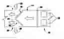
BACKGROUND OF THE INVENTIONHeating and cooling systems may incorporate a ducted unit 100 having a fan 102 and a flat coil 104 disposed inside a duct 106 (FIG. 1). Depending on the desired unit characteristics, the fan may be disposed either downstream with respect to the coil (i.e., a “draw through” architecture) or upstream with respect to the coil (i.e., a “blow through” architecture). As is know in the art, the fan 102 directs air through the duct 106 through the coil 104 so that the air can be heated or cooled as it travels through the coil 104. The coil 104 is designed to have a large surface area exposed to the air to optimize heat exchange with the air.
Normally, the coil 104 has a flat profile and is disposed either vertically or at an incline with respect to a vertical axis in the duct 106 (FIG. 1). Note that regardless of whether the coil 104 is vertical or inclined, the surface of the flat coil 104 delivers outlet air straight forward in both cases. While this coil structure is acceptable if air is discharged straight through the duct, it is less effective if the air is to be delivered at an angle (e.g., toward the sides). To discharge air from the sides, ducted units having a blow-through architecture often require one or more additional side ducts 108 downstream of the coil 104 to redirect the air. However, the side ducts make installation of the system in, for example, a residence more complicated. Further, as can be seen in FIG. 1, the side ducts 108 increase the overall system dimensions, making them impossible to install in small areas (e.g., corridors).
Also, because the flat coil 104 is designed to discharge air only in a forward direction, air that is directed laterally into the side ducts 108 will experience pressure losses, reducing the overall efficiency of the ducted unit 100.
There is a desire for a compact structure that allows the ducted unit to discharge air laterally as well as forward without the efficiency losses encountered in currently known systems.
SUMMARY OF THE INVENTIONThere is a desire for a compact structure that allows the ducted unit to discharge air laterally as well as forward without the efficiency losses encountered in currently known systems. The present invention is directed to a bent coil for use in a ducted unit and a ducted unit incorporating a bent coil. The bent coil increases the overall surface area of the coil for a given duct volume, improving the heat exchange characteristics of the coil. The bent coil discharges air both longitudinally and laterally, eliminating the need for any additional ducting downstream from the coil to divert air toward the sides. As a result, air can be directed in multiple directions while keeping the overall dimensions of the ducted unit compact.
A ducted unit incorporating the inventive bent coil according to one embodiment of the invention includes a fan and a coil that is arranged downstream from the fan, both of which are disposed in a duct. Air output from the front of the coil travels further downstream down the duct, while air diverted laterally by the coil is output through side discharge openings in the duct. The side discharge openings allow lateral air flow without requiring any additional ductwork.
BRIEF DESCRIPTION OF THE DRAWINGSFIG. 1 is a representative diagram of a prior art ducted unit;
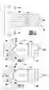
FIG. 2 is a representative diagram of a coil according to one embodiment of the invention installed in a ducted unit;
FIG. 3 is a representative diagram of a coil according to another embodiment of the invention installed in a ducted unit;
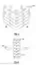
FIG. 4 is a perspective view of the coil shown in FIG. 3;
FIG. 5 is a representative diagram of a section view of one embodiment of the coil.
DETAILED DESCRIPTION OF THE EMBODIMENTSFIGS. 2 and 3 illustrate two different embodiments of an inventive coil 200 that can be used in a ducted unit. The coil 200 is a bent coil rather than a flat coil 104, creating more discharge surface area 201 than the flat coil 104 for a given duct volume. This increased surface area optimizes the available volume with the duct 106 and improves the coil's heat exchange characteristics by exposing more surface area to air. Thus, bending the coil 200 makes it possible to place a larger coil within a given fixed duct volume. FIG. 2 shows the coil 200 bent into a V-shape, while FIG. 3 shows the coil 200 bent into a curved shape. Of course, other non-linear coil configurations, such as a C-shape, M-shape, semi-circular shape, etc. are also possible without departing from the scope of the invention. Changing the profile of a vertical coil preserves the advantages of vertical coil structures generally (e.g., maintenance accessibility, water drainage during cooling operations, etc.) while still improving coil performance.
As can be seen in FIGS. 2 and 3, outlet air discharged through the coil will be directed laterally toward the sides 206 as well as toward the front 204. By orienting an air discharge surface 201 so at least a portion of the surface is angled with respect to the normal, single longitudinal outlet air flow direction (as opposed to inclined with respect to a vertical axis of the duct), the outlet air flow will be multi-directional. Further, the bent shape of the coil 200 increases the surface area of the coil 200 for a given duct volume, increasing the heat exchange capabilities of the coil 200.
FIGS. 4 and 5 illustrate one embodiment of the inventive coil 200 in more detail. Note that the structure in this coil 200 can apply to any bent coil configuration. In this embodiment, vertical fins 208 in the coil, such as aluminum vertical fins, guide air flow toward both the longitudinal and lateral directions, thereby reducing pressure losses normally associated with lateral flow. In the embodiment shown in FIG. 4, the coil 200 includes two additional vertical fins 208 to direct air perpendicular to the coil surface. The outlet air flow is thus divided into the two lateral flow paths 206 and the front flow path 204. Of course, different numbers of fins 208 may be included to direct air in different ways depending on the coil geometry and the discharge air directions.
Note that the bent profile of the coil 200 ensures that a significant amount of surface area is exposed at different angles; for example, in the case of a V-shaped bent coil 200, portions of the front surface of the coil 200 can be seen from the sides as well as from the front. This further ensures that any laterally-directed air 206 will not experience pressure or energy losses as it travels toward the sides of the coil 200.
As shown in FIG. 5, the bent coil 200 also has a plurality of vertically-arranged tubes 210. These tubes 210 are aligned vertically and staggered horizontally with respect to each other, allowing air to flow between the tubes 210 and be exposed to the maximum amount of surface area of the tubes 210. Note that in traditional flat coils 104, the tubes in the coil tend to be aligned both horizontally and vertically when the coil 104 is disposed at an incline with respect to a veridical axis in the duct 106. This allows air to flow past the tubes easily, but also causes tubes closer to the front of the coil 200 to lie directly in front of tubes closer to the back of the coil 200, thereby blocking much of the surface area of the tubes closer to the back. By keeping the coil vertical, the inventive bent coil 200 optimizes air distribution on the tubes 210 by taking full advantage of the staggering of tubes that prevent any one tube from falling within an aerodynamic shadow of another tube.
FIGS. 2 and 3 illustrate a ducted unit 250 containing the inventive bent coil 200. The ducted unit 250 includes at least one fan 252 and a separation wall 254 separating the fans 252 from the bent coil 200. A duct 256 houses at least the coil 200. As explained above, the bent coil 200 can direct outlet air 202 laterally 206 as well as toward the front 204. As a result, the ducted unit 250 can include side discharge openings 260 in the duct 256 to allow the laterally-directed air to escape. Note that the side discharge openings 260, in combination with the bent coil 200, eliminate the need for additional side ducts to direct air laterally. Because the bent coil 200 itself directs air laterally due to the fin structure described above and not due to additional ducting, air escaping the side discharge openings 260 does not experience any pressure losses due to the diversion.
The inventive coil structure therefore enables air delivery both in front of and to the sides of the coil while maximizing surface area in all directions to optimize heat exchange between the coil and the air flowing through the coil. Further, a ducted unit incorporating the inventive bent coil does not required additional, space-consuming side ducts or other equipment downstream from the coil to direct air laterally; instead, the ducted unit can simply include side openings to accommodate side ducts, relying upon the bent coil itself to direct the air through the openings. As a result, the inventive bent coil improves overall system efficiency while providing a compact, easily installable configuration.
It should be understood that various alternatives to the embodiments of the invention described herein may be employed in practicing the invention. It is intended that the following claims define the scope of the invention and that the method and apparatus within the scope of these claims and their equivalents be covered thereby.
Claims
1. An apparatus for a ducted heating and cooling unit, comprising:
a bent coil having a coil surface through which outlet air is discharged in a first direction and a second direction different than the first direction;
at least one substantially vertical fin disposed in the bent coil, wherein said at least one substantially vertical fin directs the outlet air substantially perpendicular to the coil surface to enable dividing of the outlet air in the first direction and the second direction; and
at least two fans moving unconditioned air towards the bent coil.
2. The apparatus of claim 1, wherein the first direction of the outlet air is longitudinal and the second direction of the outlet air is at an angle with respect to the first direction.
3. The apparatus of claim 1, wherein at least a portion of the bent coil is curved.
4. The apparatus of claim 1, wherein the bent coil has a V-shape profile.
5. (canceled)
6. A ducted heating and cooling unit, comprising:
a bent coil having a coil surface through which outlet air is discharged in a first direction and a second direction different than the first direction;
at least two fans moving unconditioned air towards the bent coil, wherein the bent coil is disposed in at least one of an upstream direction and a downstream direction from the at least two fans;
at least one substantially vertical fin disposed in the bent coil, wherein said at least one substantially vertical fin directs the outlet air substantially perpendicular to the coil surface to enable dividing of the outlet air in the first direction and the second direction; and
a duct that houses said at least two fans and the bent coil.
7. (canceled)
8. The ducted unit of claim 6, further comprising a separation wall disposed between said at least two fans and the bent coil.
9. The ducted unit of claim 6, wherein the duct includes at least one side opening substantially aligned with the second direction.
10. The ducted unit of claim 6, wherein the bent coil has a V-Shape profile.
11. (canceled)
12. The ducted unit of claim 8, wherein the separation wall includes at least one opening.
13. The ducted unit of claim 6, wherein the bent coil has a C-shape profile.
14. The apparatus of claim 1, wherein the bent coil has a C-shape profile.
15. The apparatus of claim 1, wherein said at least two fans move the unconditioned air in a first air direction and a second air direction different than the first air direction.
16. The ducted unit of claim 6, wherein said at least two fans move the unconditioned air in a first air direction and a second air direction different than the first air direction.
17. The ducted unit of claim 1, further comprising a separation wall disposed between said at least two fans and the bent coil.
18. The ducted unit of claim 17, wherein the separation wall includes at least one opening.
19. The apparatus as noted in claim 9, wherein said at least one side opening is ductless.
20. The apparatus as recited in claim 1, wherein said bent coil includes a plurality of tubes that are aligned vertically and staggered horizontally.
21. The ducted unit as recited in claim 6, wherein said bent coil includes a plurality of tubes that are aligned vertically and staggered horizontally.
Images & Drawings included:
Sources:
- United States Patent and Trademark Office - verify current appl. status at the USPTO↗
Similar patent applications:
- » 20060000585
Bent coil for ducted unit
Recent applications in this class:
- » 20240353116 2024-10-24
Air Blower Assembly and Ducted Air Conditioner - » 20230366563 2023-11-16
CHILLED BEAM WITH FANS - » 20230258342 2023-08-17
MINIATURE AIR MANAGEMENT SYSTEM - » 20230243521 2023-08-03
AIR PURIFIER - » 20230204227 2023-06-29
Air conditioner - » 20220268453 2022-08-25
Heat exchange device and refrigerant circulation system - » 20210172618 2021-06-10
AIR MANAGEMENT APPARATUS OR DEVICE - » 20210172617 2021-06-10
Air management apparatus or device - » 20210172616 2021-06-10
Air management apparatus or device - » 20210156571 2021-05-27
Air conditioner having fan module with installation space and stabilizer modifier spaced apart from the fan module