Compact solar heater
US20050183717A1
2005-08-25
11/054,493
2005-02-09
Abstract:
A compact solar heater has a one-piece body having a tank part and a coil part, with an entrance of the coil part for a cold water connected to the tank part and an exit of the coil part for hot water connected to the tank part, a solar ray resistant and transparent element arranged above a coil in the coil part to provide an internal space between the transparent element and the coil which acts as a greenhouse, wherein the transparent element has accommodation edges which are plane and coplanar with each other and with a remaining portion of the transparent element, and a flow control assembly is arranged in a passing hole in a side of the tank part and operative for monitoring a water level contained in the tank part and for controlling a water flow circulating in the heater as a whole, to automatically ensure a replacement of cold water at the entrance of the coil part as an exit of hot water from the tank is open.
Interested in similar patents?
Get notified when new applications in this technology area are published.
Classification:
F24S60/30 » CPC main
Arrangements for storing heat collected by solar heat collectors storing heat in liquids
Y02B10/20 » CPC further
Integration of renewable energy sources in buildings Solar thermal
Y02B10/20 » CPC further
Integration of renewable energy sources in buildings Solar thermal
Y02E10/40 » CPC further
Energy generation through renewable energy sources Solar thermal energy, e.g. solar towers
Y02E10/40 » CPC further
Energy generation through renewable energy sources Solar thermal energy, e.g. solar towers
Description
BACKGROUND OF THE INVENTIONThe present invention generally relates to compact solar heaters, which are used for heating water passage in hydraulic plants of commercial and/or domestic buildings.
As well known by technicians in the art, the water heating through passage have been used for many years, from boilers to electrical systems where the water flow passes through electrical resistance, obtaining an instantaneous water heating used in electrical showers and taps.
In general, the boilers are used where the consumption is very high and continuous, for example in companies and edifices that need a constant and high-volume supply. This solution has a very high operational cost, since the fuel, generally gas, fossil or wood coal, has a high cost and implies the heating of the same water mass if the consumption is temporarily reduced.
The passage heaters that use electrical resistances are intended for smaller water volumes and almost punctual application by the use of showers and taps that requires hot water momentarily and in small volume. Although this solution has only consumption of energy during the water passage, since there is no need of a place to store the hot water, it has a high cost.
Another type of water heating through passage appeared with the coming of photovoltaic cells, which are used in solar heaters that capture solar energy for heating the water that passes through a heating area. As it is already known, the working principle of these solar heaters is very simple. Where a duct, preferably metallic and painted in black, is put with a coil inside a box internally painted in black, and superiorly closed with a transparent glass plate, a duct inferiorly and superiorly connected to the water tank allows that this water heats due to the direct reception of solar radiation and the air heated through the greenhouse effect caused by the glass. Due to the convection generated in the system, the water circulates continuously, launching hot water in the upper part of the thermal tank and removing cold water from the lower part. This process repeats itself while there is sunlight and still allows the supply of hot water gratuitously, being the heated water volume directly proportional to the sun incidence and quantity of radiation collectors. Although this equipment is sophisticated and has a high cost, its amortization is quick, since the necessary energy to heat the water has no cost.
Different types and models of water heaters through capture of solar energy, despite being efficient and advantageous, have the disadvantage that their conception and assembly require complex construction processes, well diversified and specialized labor and the use of noble and consequently expensive materials, therefore having a reduced productivity.
Other inconveniences of these conventional solar heaters refer to their installation on the roof of the building that requires a space between the cement slab and ridge of approximately two meters with proper reinforcement to receive the thermal tank, and if such space is not available a proper structure must be built out of the roof to receive it. Thus, this installation is very complex, requiring specialized labor and therefore having a high cost. To minimize the above difficulties, this type of heater is conventionally installed during building, since the problems of installation are perfectly equated and solved.
A compact and modular solar water heater is disclosed in Brazilian patent PI9405029-1 by the applicant, in which the above mentioned problems are minimized. It is constructed through a manufacturing process where all the assembly is preformed in one part only and obtained in one operation only, drastically decreasing the manufacturing time, since it eliminates the need of specialized labor and complex and long stages of assembly. The proposed water heater allows to simplify its installation since it does not need many changes in the buildings, besides the reinforcement in the roof structure.
The compact solar water heater disclosed in this patent is composed of two metallic or non-metallic plates with the use of the process of blowing, injection, rotomolding, thermal forming and stamping and welding of the plates and has a coil and a water tank connected through a short tubing section. This very compact heater can be installed on the roof with reinforced internal structure or on an inclined support on the cement slab, in necessary quantities to heat the desired volume of water.
Although it represents a significant and constructive advance against the conventional solar heaters, this compact solar heater can be further improved to become more efficient in terms of heating capacity and more diversification in the assembly of the flow control system.
SUMMARY OF THE INVENTIONAccordingly, it is an object of the present invention to provide a compact solar heater, which is a further improvement of the existing solar heaters.
In keeping with these objects and with others which will become apparent hereinafter, one feature of the present invention resides, briefly stated, in a compact solar heater, comprising a one-piece body having a tank part and a coil part, and means for connecting said tank part to an entrance of said coil part for a cold water descent from said tank part to said coil part and for connecting an exit of said coil part with said tank part for hot water ascent from said coil part to said tank part; a solar ray resistant and transparent element arranged above a coil in said coil part to provide an internal space located between said transparent element and said coil and acting as a greenhouse, said transparent element having accommodation edges which are plane and coplanar with each other and with a remaining portion of said transparent element; and a flow control assembly arranged in a passing hole in a side of said tank part and operative for monitoring a water level contained in said tank part and for controlling a water flow circulating in the heater as a whole, to automatically ensure a replacement of cold water at said entrance of said coil part as an exit of hot water from said tank is open.
When the compact solar heater is designed in accordance with the present invention, a thickness of the coil part is reduced because the accommodation edges of the transparent plate are plane and coplanar, and also due to the mounting of the flow control assembly it is possible to temporize the circulation of the water in the heater according to the conditions and times of sun incidence in the plate of capture of solar energy.
The novel features which are considered as characteristic for the present invention are set forth in particular in the appended claims. The invention itself, however, both as to its construction and its method of operation, together with additional objects and advantages thereof, will be best understood from the following description of specific embodiments when read in connection with the accompanying drawings.
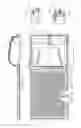
BRIEF DESCRIPTION OF THE DRAWINGSFIG. 1 is a plan view of a compact solar heater in accordance with the present invention, with a section showing an arrangement of a coil and a transparent element for forming a greenhouse effect;
FIG. 2 is a view showing a longitudinal section of the compact solar heater shown in FIG. 1;
FIG. 3 is a view showing an amplified detail of a side of the compact solar heater with a water filling control assembly configured as a mechanical assembly with a float valve; and
FIG. 4 is a view showing an amplified detail of a side of the compact solar heater with a temporized water filling control assembly, configured as an electronic assembly.
DESCRIPTION OF THE PREFERRED EMBODIMENTSA compact solar heater in accordance with the present invention has a one-piece body which is identified with reference numeral 10 and composed of two plates 1 with the use of a process of blowing, injection, rotomolding and thermal forming, joint by a perimetral compressing 1A. The one-piece body 10 forms a tank 2 and a coil 4, both having a flat bottom. The tank 2 is protected with a finishing cover 3 which is provided with an inner layer 3a of a thermal insulating material, as shown in FIG. 2.
The tank 2 is connected to an entrance edge of the coil 4 by a tubing section 5 which is provided for cold water descent from the tank 2 to the coil 4 and formed by an interruption of the perimetral compression 1A of the plates 1. The cold water feeds the lower part of the coils 4. An exit edge of the coil 4 is connected to the tank 2 by a tubing section 6 which is inclined in an ascending way and formed by interruptions of the perimetral compression 1A of the plates 1, for hot water ascent from the coil 4 to the tank 2.
A solar ray resistant and transparent element 7 is arranged above the coil 4 so as to leave an internal space 8 that will act as a greenhouse. It can be composed for example of a transparent glass.
As can be seen from FIGS. 1 and 2, intermediately to the compression plane 1A of the plates 1 there are accommodation edges 1B of the transparent element 7. The accommodation edges 1B of the transparent plate 7 are plane and coplanar with one another and also with a remaining portion of the transparent plate 7, so as to ensure a reduction of the thickness of the coil part and thereby an increase of the greenhouse effect, since a smaller air layer is defined between the transparent plate and the coil, accelerating the heating process of the air volume contained inside it and consequently accelerating the heating of the water circulating by the coil 4.
As shown in FIGS. 3 and 4, a passing hole 2A provided in the side of the tank and extends through the tank 2 and its covering 3, for selective coupling and retention of a flow control assembly. The flow control assembly is provided for monitoring a water layer contained in the tank 2 and controlling a water flow circulating in the heater 10 as a whole, so as to automatically ensure the replacement of cold water in the entrance 5 of the coil 4, as an exit 9 of hot water from the tank 2 is open.
In the embodiment shown in FIG. 3, the flow control assembly is formed as a mechanical flow control assembly 20 including a float valve. This system is used in water tanks, allowing the replacement of cold water immediately when the exit of hot water consumption is open.
This assembly, despite being widely used, allows the loss of temperature due to the mixture of the hot water contained in the tank 2 with the cold water entering the tank 2 at night, when the water circulating in the coil 4 obviously is not heated due to the lack of solar energy.
In the embodiments shown in FIG. 4, the flow control assembly 30 is temporized and electronic. This assembly allows to control the cold water filling time, that is the assembly allows the entrance of cold water during the day between 8:00 and 17:00 blocking the entrance of cold water after 17:00, avoiding the mixture of cold water with hot water contained in the tank 2 during the period of more use of hot water that is usually after 17:00. Thus, in this version during the night the hot water supply is limited to the volume contained in the tank 2.
In accordance with the present invention, preferably the descent tubing 5 of cold water has an increase of diameter from the tank 2 toward the coil 4, while the ascent tubing 6 of hot water has an increase of diameter from the coil 4 toward the tank 2.
Preferably, the tubing 6 of hot water has a higher ascent inclination, which facilitates the ascent of hot water to the tank 2, improving the performance of the apparatus.
It will be understood that each of the elements described above, or two or more together, may also find a useful application in other types of constructions differing from the types described above.
While the invention has been illustrated and described as embodied in a compact solar heater, it is not intended to be limited to the details shown, since various modifications and structural changes may be made without departing in any way from the spirit of the present invention.
Without further analysis, the foregoing will so fully reveal the gist of the present invention that others can, by applying current knowledge, readily adapt it for various applications without omitting features that, from the standpoint of prior art, fairly constitute essential characteristics of the generic or specific aspects of this invention.
Claims
1. A compact solar heater, comprising a one-piece body having a tank part and a coil part, and means for connecting said tank part to an entrance of said coil part for a cold water descent from said tank part to said coil part and for connecting an exit of said coil part with said tank for hot water ascent from said coil part to said tank part; a solar ray resistant and transparent element arranged above a coil in said coil part to provide an internal space between said transparent element and said coil which acts as a greenhouse, said transparent element having accommodation edges which are plane and coplanar with each other and with a remaining portion of said transparent element; and a flow control assembly arranged in a passing hole in a side of said tank part and operative for monitoring a water level contained in said tank part and for controlling a water flow circulating in the heater as a whole, to automatically ensure a replacement of cold water at said entrance of said coil part as an exit of hot water from said tank part is open.
2. A compact solar heater as defined in claim 1, wherein said means for connecting include a first tubing section which connects said tank part with said entrance of said coil part, and a second tubing section for connecting said exit of said coil part with said tank part.
3. A compact solar heater as defined in claim 1, wherein said one-piece body is composed of two plates and has a flat bottom.
4. A compact solar heater as defined in claim 1, wherein said tank part has a finishing cover provided with an inner layer of a thermal insulating material.
5. A compact solar heater as defined in claim 1, wherein said flow control assembly is configured as a mechanical assembly and has a float valve.
6. A compact solar heater as defined in claim 1, wherein said flow control assembly is configured as a temporized and electronic assembly.
7. A compact solar heater as defined in claim 1, wherein said flow control assembly is configured so as to allow an entrance of cold water during a day between 8:00 and 17:00, blocking the entrance of cold water after 17:00, avoiding a mixture of cold water with hot water contained in said tank part during a period of more use of hot water that usually is after 17:00.
8. A compact solar heater as defined in claim 2, wherein said first tubing for cold water is configured as a descent tubing having an increasing diameter from said tank part toward said coil part, said second tubing for hot water being configured as an ascent tubing with an increasing diameter from said coil part toward said tank part.
Images & Drawings included:

Sources:
- United States Patent and Trademark Office - verify current appl. status at the USPTO↗
Recent applications in this class:
- » 20240230165 2024-07-11
MULTILAYERED ION EXCHANGE MEMBRANES - » 20220228777 2022-07-21
Hardened solar energy collector system - » 20220186983 2022-06-16
Solar heat collector and solar water heater - » 20220136738 2022-05-05
Top-Surface-Cooled, Directly Irradiated Liquid Receiver For Concentrated Solar Power - » 20210396429 2021-12-23
High pressure hydrogen electrical power generator - » 20210231348 2021-07-29
Solar water heating system - » 20190346179 2019-11-14
Curved surface absorber type solar fluid heater - » 20120227730 2012-09-13
Coaxial tube solar heater with nighttime cooling - » 20120210999 2012-08-23
SOLAR HEATING SYSTEM FOR A HOT WATER HEATER - » 20120180781 2012-07-19
Solar heater system for domestics waters