Method and apparatus for manufacturing a polarizer
US20060127596A1
2006-06-15
11/298,351
2005-12-09
Abstract:
A method for manufacturing a polarizer includes: providing a substrate; coating the substrate with a polarizing layer; orienting most of the molecules of the polarizing layer by using a plurality of roller devices; and using a laser device to orient the remaining molecules. The method can increase the shape anisotropy of the polarizer. When the polarizer is used in an LCD (liquid crystal display) device, light provided for a display of the LCD device is increased, and the light utilization rate of the LCD device is improved. The polarizer manufacturing apparatus can further include a transducer between each roller and the substrate having the polarizing layer.
Assignee:
- HON HAI Precision Industry CO., LTD. 1,310 🇹🇼 Tu-Cheng City, Taiwan
Interested in similar patents?
Get notified when new applications in this technology area are published.
Classification:
G02B5/30 » CPC main
Optical elements other than lenses Polarising elements
G02B5/3016 » CPC further
Optical elements other than lenses; Polarising elements involving passive liquid crystal elements
B05D5/06 IPC
Processes for applying liquids or other fluent materials to surfaces to obtain special surface effects, finishes or structures to obtain multicolour or other optical effects
B05C11/02 IPC
Component parts, details or accessories not specifically provided for in groups - Apparatus for spreading or distributing liquids or other fluent materials already applied to a surface ; Controlling means therefor ; Control of the thickness of a coating by spreading or distributing liquids or other fluent materials already applied to the coated surface
Description
BACKGROUND1. Field of the Invention
The present invention relates to a method and an apparatus for manufacturing an optical polarizer.
2. General Background
Liquid crystal display (LCD) devices are in widespread use in personal computers, desk-top calculators, electronic clocks, word-processors, automobiles, and other machines. Nearly all LCD devices include one or more polarizers, which function as filters with regard to the polarization of light.
A typical method for manufacturing a liquid crystal material polarizer is set out in FIG. 3. The method includes the following steps: providing a containment medium for containing the liquid crystal material; casting an emulsion of liquid crystal material with pleochroic dye in the containment medium; and stretching such cast material to form elongate volumes of liquid crystal and pleochroic dye in such containment medium using a plurality of roller devices.
However, a performance of a liquid crystal material polarizer manufactured by the typical method can not be satisfactorily used in an LCD device, because a shape anisotropy of the polarizer is not optimized throughout.
What is needed, therefore, is a method and an apparatus for manufacturing an optical polarizer with optimized shape anisotropy.
SUMMARYIn one preferred embodiment, a method for manufacturing a polarizer for an LCD device includes the following steps: providing a substrate; coating the substrate with a polarizing layer; orienting most of the molecules of the polarizing layer by using a plurality of roller devices; and then using a laser device to orient the remaining molecules. The method improves the shape anisotropy of the polarizer. When the polarizer is used in an LCD device, light provided for a display of the LCD device is increased, and the light utilization rate of the LCD device is optimized.
In another preferred embodiment, an apparatus for manufacturing a polarizer includes a plurality of roller devices arranged on two sides of a path for passage of a polarizer preform, and a laser device arranged next in processing sequence after the roller devices. The polarizer manufacturing apparatus can further include a plurality of transducers, each transducer being located between a respective roller and a polarizer layer of the polarizer preform.
Other advantages and novel features will become more apparent from the following detailed description of preferred embodiments when taken in conjunction with the accompanying drawings, in which:
BRIEF DESCRIPTION OF THE DRAWINGSFIG. 1 is a flow chart of a method for manufacturing a polarizer in accordance with one preferred embodiment of the present invention;
FIG. 2 is a schematic, side view of an apparatus for manufacturing a polarizer in accordance with another preferred embodiment of the present invention, together with a polarizer preform; and
FIG. 3 is a flow chart of a conventional method for manufacturing a polarizer.
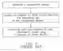
DETAILED DESCRIPTION OF THE EMBODIMENTSFIG. 1 shows a method for manufacturing a polarizer according to a preferred embodiment of the present invention. The method includes the following steps.
First, providing a substrate. The substrate can be made from transparent glass or plastic.
Second, coating the substrate with a polarizing layer. The polarizing layer is coated on one main side of the substrate, and can be made from polyvinyl alcohol (PVA) embedded with a polarizing material. The polarizing material can be an iodine type polarizing material, a dye type polarizing material, a polyvinyl polarizing material such as fluorinated polyimide, or a metallic polarizing material such as Ag—As—S material. The polarizing layer is for transforming natural light into linear polarized light.
Third, orienting the molecules of the polarizing layer using a plurality of roller devices. The roller devices apply contact force on the polarizing layer, whereby a significant number of the molecules of the polarizing layer are oriented into a preferred orientation to improve shape anisotropy of the polarizing layer. The roller devices can comprise common rollers, and/or rollers with electrodes. When rollers with electrodes are used adjacent the polarizing layer, the molecules of the polarizer are oriented by the electric field between the electrodes of the rollers. In addition, the contact force applied to the polarizing layer by the roller devices can be measured by a sensor arranged in each roller. The contact force can be adjusted by a transducer arranged between each roller and the substrate having the polarizing layer. The sensor and the transducer are described in more detail below in relation to FIG. 2.
Finally, orienting the remaining molecules of the polarizing layer using a laser device. The laser device irradiates the polarizing layer with laser beams. The laser beams can be polarized laser beams. Because laser beams have the properties of high energy density and a regular phase, the laser beams do not diffuse during propagation. Thus, the remaining molecules of the polarizing layer can be oriented.
After most molecules of the polarizing layer are oriented by the roller devices, the remaining molecules are oriented by laser beams from the laser device for further creating shape anisotropy. Thus, the shape anisotropy and the polarization of the polarizer are improved. When the polarizer is used in an LCD device, light provided for a display of the LCD device is increased, and the light utilization rate of the LCD device is improved.
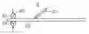
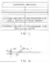
FIG. 2 shows an apparatus for manufacturing a polarizer according to another preferred embodiment of the present invention. The apparatus 2 includes a plurality of roller devices 20 arranged on two sides of a path for passage of a polarizer preform 22, and a laser device 23 arranged next in processing sequence after the roller devices 20. The polarizer preform 22 includes a substrate (not shown) and a polarizing layer (not shown) coated on a top of the substrate. Each roller device 20 includes a piezoelectric sensor 21 disposed therein, for detecting and controlling contact force applied to the polarizer preform 22 by the roller device 20. An angle between the laser device 23 and the normal of the polarizer preform 22 is in the range from 30° to 75°. The roller devices 20 can cooperatively apply contact force to the polarizer preform 22 passing therebetween, in order to create a desired shaped anisotropy of the polarizer preform 22 and orient the molecules of the polarizer layer. Thereafter, the laser device 23 irradiates the polarizing layer, thereby orienting the remaining molecules.
It is of advantage that the shape anisotropy of the polarizer preform 22 is further improved by the laser beams from the laser device 23. When a polarizer manufactured by the apparatus 2 is used in an LCD device, light provided for a display of the LCD device is increased, and the light utilization rate of the LCD device is improved.
In alternative embodiments, the method for manufacturing the polarizer can further include coating an anti-reflection layer and/or an anti-glare layer on a surface of the polarizer.
It is believed that the present embodiments and their advantages will be understood from the foregoing description, and it will be apparent that various changes may be made thereto without departing from the spirit and scope of the invention or sacrificing all of its material advantages, the examples hereinbefore described merely being preferred or exemplary embodiments of the invention.
Claims
What is claimed is:1. A method for manufacturing a polarizer, comprising the following steps:
providing a substrate, and coating the substrate with a polarizing layer;
orienting molecules of the polarizing layer using a plurality of roller devices; and
orienting molecules of the polarizing layer using a laser device.
2. The method as claimed in claim 1, wherein the polarizing layer comprises polyvinyl alcohol embedded with polarizing material.
3. The method as claimed in claim 2, wherein the polarizing material comprises iodine type polarizing material.
4. The method as claimed in claim 2, wherein the polarizing material comprises dye type polarizing material.
5. The method as claimed in claim 2, wherein the polarizing material comprises polyvinyl polarizing material.
6. The method as claimed in claim 5, wherein the polyvinyl polarizing material comprises fluorinated polyimide.
7. The method as claimed in claim 2, wherein the polarizing material comprises metallic polarizing material.
8. The method as claimed in claim 7, wherein the metallic polarizing material comprises Ag—As—S material.
9. The method as claimed in claim 1, further comprising coating an anti-reflection layer on a surface of the polarizer.
10. The method as claimed in claim 1, further comprising coating an anti-glare layer on a surface of the polarizer.
11. The method as claimed in claim 1, wherein light emitted from the laser device is polarized.
12. An apparatus for manufacturing a polarizer, comprising:
a plurality of roller devices arranged on two sides of a path for passage of a polarizer preform; and
a laser device arranged next in processing sequence after the roller devices.
13. The apparatus as claimed in claim 12, wherein each roller device comprises a piezoelectric sensor.
14. The apparatus as claimed in claim 12, further comprising at least one transducer associated with the roller devices.
15. The apparatus as claimed in claim 12, wherein an angle between the laser device and the normal of the polarizer preform is in the range from 30° to 75°.
16. A method for manufacturing a polarizer, comprising the steps of:
preparing a substrate as a main portion of a polarizer;
coating a polarizing layer onto said substrate;
normally pressing said polarizing layer toward said substrate for orienting molecules of said polarizing layer; and
laser-treating said polarizing layer for further orienting molecules of said polarizing layer.
17. The method as claimed in claim 16, wherein at least two rollers are respectively movably arranged at two sides of a passing path for said substrate so as to be moved against said passing substrate in order for providing said normally pressing onto said polarizing layer.
Images & Drawings included:
Sources:
- United States Patent and Trademark Office - verify current appl. status at the USPTO↗
Similar patent applications:
- » 20120170117
POLARIZER PLATE, OPTICAL APPARATUS, AND METHOD OF MANUFACTURING POLARIZER PLATE - » 20200209451
Polarizing plate, optical apparatus and method of manufacturing polarizing plate - » 20120081671
Polarization conversion element, polarization conversion unit, projection apparatus, and method for manufacturing polarization conversion element having a thin ultraviolet light curing adhesive layer - » 20120105745
Polarization element, projector, liquid crystal device, electronic apparatus, and method of manufacturing polarization element - » 20060018018
Polarizing element, method of manufacturing polarizing element, method of evaluating exposure apparatus, method of manufacturing semiconductor device, and exposure apparatus - » 20050233096
Polarizer, method of manufacturing the polarizer, apparatus for manufacturing the polarizer, and display apparatus having the polarizer - » 20180292747
PROCESSING APPARATUS OF POLARIZER AND MANUFACTURING METHOD THEREOF - » 20070165157
APPARATUS AND METHOD FOR MANUFACTURING POLARIZER - » 20120319222
Solid-state imaging element, solid-state imaging device, imaging apparatus, and method of manufacturing polarizing element - » 20190257991
Method for manufacturing a polarizer apparatus, polarizer apparatus, and display system having a polarizer apparatus
Recent applications in this class:
- » 20230296819 2023-09-21
DISPLAY MODULE AND DISPLAY DEVICE - » 20230273357 2023-08-31
DEVICE AND METHOD FOR IMAGE PROCESSING - » 20230204837 2023-06-29
GLARE REDUCTION SYSTEM - » 20230135197 2023-05-04
REFLECTION PREVENTION STRUCTURE - » 20230055877 2023-02-23
POLARIZING PLATE AND OPTICAL DISPLAY DEVICE COMPRISING SAME - » 20220221640 2022-07-14
Optical element driving mechanism - » 20220137276 2022-05-05
IMAGING APPARATUS - » 20220082745 2022-03-17
IMAGING APPARATUS - » 20220057557 2022-02-24
OPTICAL FILM WITH ADHESIVE LAYER, IMAGE DISPLAY PANEL AND IMAGE DISPLAY DEVICE - » 20220003910 2022-01-06
ALIGNING A POLARIZATION DEVICE USING A SPATIALLY VARIANT POLARIZATION ELEMENT
Recent applications for this Assignee:
- » 20140363586 2014-12-11
Laser-based method for growing an array of carbon nanotubes - » 20140299819 2014-10-09
Method for making a carbon nanotube film - » 20140199855 2014-07-17
Method for making a carbon nanotube film - » 20110171419 2011-07-14
Electronic element having carbon nanotubes - » 20110110535 2011-05-12
Carbon nanotube speaker - » 20110036826 2011-02-17
Carbon nanotube heater-equipped electric oven - » 20110032196 2011-02-10
Touch panel and display device using the same - » 20110027486 2011-02-03
Method for preparing transmission electron microscope sample - » 20110024410 2011-02-03
Carbon nanotube heater - » 20110020563 2011-01-27
Carbon nanotube film composite structure, transmission electron microscope grid using the same, and method for making the same