Windmill blade shaping and mounting to enhance performance
US20060239821A1
2006-10-26
11/407,727
2006-04-19
✅ Patent granted
US 7,513,746 B2
2009-04-07
-
-
Igor Kershteyn
2027-01-26
Abstract:
A method of mounting windmill blades their enhance performance is disclosed. The blades have a transverse cross-sectional shape having a predominately flat chord section and are mounted such that the chord section lies in a plane that is substantially at 90 degrees to the axis of the shaft upon which they are mounted.
Inventors:
- Francis J. McCabe 4 🇺🇸 Ottville, PA, United States
- Francis J. McCabe 1 🇺🇸 Ohville, PA, United States
Assignee:
- OmniWind Energy Systems LLC 2 🇺🇸 Dublin, PA, United States
Interested in similar patents?
Get notified when new applications in this technology area are published.
Classification:
F03D1/0608 » CPC main
Wind motors with rotation axis substantially parallel to the air flow entering the rotor ; Rotors characterised by their form
F03D1/065 » CPC further
Wind motors with rotation axis substantially parallel to the air flow entering the rotor ; Rotors characterised by their construction, i.e. structural design details
F03D7/0224 » CPC further
Controlling wind motors the wind motors having rotation axis substantially parallel to the air flow entering the rotor; Adjusting aerodynamic properties of the blades Adjusting blade pitch
F03D13/10 » CPC further
Assembly, mounting or commissioning of wind motors; Arrangements specially adapted for transporting wind motor components Assembly of wind motors; Arrangements for erecting wind motors
F05B2240/911 » CPC further
Components; Mounting on supporting structures or systems on a stationary structure already existing for a prior purpose
Y02E10/72 » CPC further
Energy generation through renewable energy sources; Wind energy Wind turbines with rotation axis in wind direction
Y02E10/72 » CPC further
Energy generation through renewable energy sources; Wind energy Wind turbines with rotation axis in wind direction
Y02E10/728 » CPC further
Energy generation through renewable energy sources; Wind energy Onshore wind turbines
Y02E10/728 » CPC further
Energy generation through renewable energy sources; Wind energy Onshore wind turbines
Y10S415/908 » CPC further
Rotary kinetic fluid motors or pumps; Natural fluid current motor Axial flow runner
F03D3/06 IPC
Wind motors with rotation axis substantially perpendicular to the air flow entering the rotor Rotors
Description
CROSS-REFERENCE TO RELATED APPLICATIONSThis application is a Continuation-in-Part of my prior Provisional application entitled Squish swish windmill blade to enhance performance, Ser. No. 60/673,508, filed Apr. 21, 2005 the disclosure of which is incorporated herein by reference as if fully set forth.
BACKGROUND OF THE INVENTION1. Technical Field of the Invention
This invention relates to airfoil shapes and their mounting, and to add-on blades to enhance the performance of windmills.
2. Description of the Art
The existing art focuses on a very seductive windmill aerodynamics sometimes called ‘planar flow’, ‘kiting’ or my own deflected air flow as a “squished” sheet of air' that accelerates after impacting against virtually flat to the wind blade(s). A body of moving air (wind) can be squished down to a very thin sheet that is moving off the trailing edge of a blade at up to 10 times the relative speed of the incoming air to the departing rotating blade. The currently used blade design force dynamics produces this great rotating speed, but with little usable torque.
SUMMARY OF INVENTIONI have invented a new airfoil mounting performance principle (optimal center of pressure caused angle of attack positioning). The new aerodynamics means any windmill will be dramatically improved at much lower air speeds.
BRIEF DESCRIPTION OF THE DRAWINGSFIG. 1A is a front view of a windmill assembly having my new blade design and positioning;
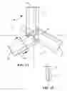
FIG. 1B is a portion of a blade and shaft showing the preferred relative positioning range;
FIG. 2 is a side view of the windmill assembly shown in FIG. 1;
FIG. 3 is a rear view of the windmill assembly shown in FIG. 1;
FIG. 4 is a side view of a blade;
FIG. 5 is a side view of another blade mounted to a hub;
FIG. 6 is a side view of a blade mounted to a hub in a different manner;
FIG. 7 is a front view of a windmill blade arrangement in accordance with my invention shown mounted to a hub of a prior art windmill; and
FIG. 8 is a side view of the apparatus shown in FIG. 7.
DESCRIPTION OF THE PREFERRED EMBODIMENTSThe preferred embodiments are disclosed in the attached drawings, from which it will be appreciated that I have invented a high-speed airfoil for use on the rotor of a windmill which also can be mounted in front of an existing rotor. The blade has a leading edge lip ahead of the squish—to make the swish—with good torque.
The blades may be approximately one half the diameter of existing blades—when used in the “piggy back” mounting (in front of standard blades) as shown in FIGS. 7 and 8.
My new blades add power, while providing some braking to reduce speed. This new airfoil design (with optional hinged blade mounting mechanics) recognizes and enhances the ‘squish’ power potential with two innovations.
- 1. A start up initial/high angle of attack (non squish) positioning option that handles the detrimental slow starting and also allows a higher load handling capability by utilizing the changing center of (wind) pressure phenomenon to:
a) initially (for more start-up power) hold the blade at the higher torque providing lower angle of attack to wind from approximately 80 degrees to 65 degrees, and
b) as (if) the lower torque speed up occurs transferring the air pressure (squish) resultant more directly against the ‘blade edge’ (now with leading edge air catcher lip) geometric pivoting raises the angle of attack to the high speed position—without springs or other extra force means.
- 2. Imposing the leading edge air catcher forward lip that provides an air blocking surface for significantly enhanced novel leading edge pressure differential “squish” retaining surface increase, which allows a more effective high rpm turning air power resultant. The impinged air then can more likely jet off the trailing edge because the flattened air sheet is blocked at the leading edge.
Other enhancements include: - More (up to eight) blades.
- Leading edge (forward tip) blade rake.
- A slight bend into the wind, trailing section angle, that permits another flow dynamic of planar jetting enhancements of outgoing air just as it leaves the trailing edge additionally inhibits underside pressure overrun from the blade bottom to top which would reduce pressure differential. There is also the relative air speed differential causing a push back against the blade (and forward lip). It also does some ordinary windmill pressure aerodynamics at the trailing edge section.
A root shape geometric that again employs ordinary Bernoulli and McCabe (‘windmilling aerodynamics’) of the slower moving (near hub) blade section.
The blade is very thin, more easily slicing through the air—displacing less mass—even with the forward lip which is effectively inconsequential into the air as it is essentially one with the forward portion of the impinged air which would normally encounter just the air (resistance) and give away power transfer to the blade that is now pushing against the leading edge lip.
In small diameter wind turbines it is more effective when the blade is twisted so that the blade root is at an angle of attack of 10 to 15 degrees to rotation; most preferably 11 to 14 degrees; and the outer (faster) tip is at 8-10 degrees less to the plane of rotation.
In larger diameter mills blade twist is less critical, so production costs can be reduced by having a constant angle (no twist). This constant angle is best in the 7-10 degree angle to the plane of rotation (80-83 degrees to the wind).
Referring to FIG. 1, three blades 10 are fastened to a hub 12 by any suitable means, such as the rivets 14. The hub is mounted on a shaft 16 to rotate the shaft in the direction of the arrow “A” upon action of the wind (moving in the direction of the “AIR FLOW” arrow shown in FIG. 2).
A typical blade cross-section taken as indicated by the lines and arrows 4-4 in FIG. 1A, is shown in FIG. 4. Such a structure is shown generally in my prior U.S. Patent No. 5,711,653 and comprises a planar face or chord portion, leading and trailing edges angled to said chord portion such that the cross-section is a pan shape; and a portion extending from one edge back toward the chord portion. It has an overall length of “C” and a chord length “B” along the largest, substantially flat chord blade section. For use in the present invention, the profile of the blade is substantially flatter than my prior blades. In particular, for a chord length of four and one-half inches, the total height—including the lip—is five eights of an inch.
In addition, I provide end caps 26 FIG. 1A to close off the radial ends of the pan shaped structure.
The hub 12 is flat (that is, at 90 degrees) to the wind “AIR FLOW” as shown in FIG. 2. The blade chord portion “B” is also substantially at 90 degrees to the air flow (in a plane taken at 90 degrees to the axis of the shaft 16). When the air hits the blade it spreads out over the blade and eventually runs into and builds up against the lip designated generally 18 FIG. 4; which is the leading edge. The other edge is referred to as the trailing edge.
In the preferred embodiment, the lip may be shaped as at 20, FIG. 5 and the blade may be positioned at an angle “D”. This positions the blade in the range of 78 to 87 degrees; as distinguished from 90 degrees.
Test results are shown in the following chart.
Comparison of 4.5 inch air foils in a small wind tunnel at a wind speed of 15 mph
| Degrees | |||
| of angle | new aerodynamic | old aerodynamic | typical |
| of | mounting (NASS) | mounting of my | air foil |
| attack | squish/swish | Patented blades | NACA 0012 |
| 90 | 0.5 lb of rotational | 0.3 lb of rotational | 0.3 lb of rotational |
| force | force | force | |
| 85 | 0.6 | 0.4 | 0.4 |
| 80 | 0.7 | 0.5 | 0.5 |
| 75 | 0.8 | 0.7 | 0.6 |
These results show that the new aerodynamics squish/swish (NASS) flat against the wind positioning (between 90 and 75 degrees) out performs the old aerodynamics and standard air foils by a ⅔ increase.
In the normal angle of attack range, the NASS air foil out performs the standard airfoil by 25-35%. More recent testing suggests a preferred range of 78 to 83 degrees.
As can be seen, the NASS is a fast rotating wind turbine air foil that has vastly higher torque than standard air foils.
While the blade may be mounted in a fixed position; as shown by the nut and bolt arrangement designated generally at 22 FIG. 5; an adjustable arrangement can be used as for example by the addition of a spring 24 FIG. 6. This allows for field setting of the angle.
The preferred location of the blades with respect to the center line of the shaft is off-center. Referring to FIG. 1B, the leading edge (lip) is most preferably in the range of (F) ⅓ to ¼ of the width of the blade from the center line of the shaft. This produces a leading edge rake which helps keep the air flow aligned perpendicularly to the blade.
End caps 26 at the outer edges of the blades 10 FIG. 1A help keep the air from spilling off the blade.
The air foil may also be mounted in front of an existing prior art rotor blade 30 of a wind turbine 32 as shown in FIGS. 7 and 8, to enhance power output.
From this description it has been shown that I have invented a windmill having blades mounted on a shaft, at least some of which blades have a transverse cross-sectional shape having a predominately flat chord section, said blades being mounted such that the chord section lies in a plane that is substantially at 90 degrees to the axis of the shaft. The plane may be positioned at an angle in the range of 78 to 87 degrees to the axis of the shaft. Furthermore, the blades can be positioned off-center to the axis of the shaft.
The blades have a leading edge positioned in the range of ¼ to ⅓ the width of the blade from the axis of the shaft.
The windmill may be mounted in front of the blades of a wind turbine.
I have also invented a method of mounting windmill blades on the shaft of a windmill, at least some of which blades have a transverse cross-sectional shape having a predominately flat chord section, comprising mounting said blades such that the chord section lies in a plane that is substantially at 90 degrees to the axis of the shaft.
The plane may be at an angle in the range of 78 to 87 degrees to the axis of the shaft.
The blades may be positioned off-center to the axis of the shaft.
The blades have a leading edge positioned in the range of ¼ to ⅓ the width of the blade from the axis of the shaft.
The windmill may be mounted in front of the blades of a wind turbine.
Claims
What is claimed is:1. A windmill having blades mounted on a shaft, at least some of which blades have a transverse cross-sectional shape having a predominately flat chord section, said blades being mounted such that the chord section lies in a plane that is substantially at 90 degrees to the axis of the shaft.
2. The windmill of claim 1 wherein the plane is positioned at an angle in the range of 78 to 87 degrees to the axis of the shaft.
3. The windmill of claim 1 wherein the blades are positioned off-center to the axis of the shaft.
4. The windmill of claim 3 wherein the blades have a leading edge positioned in the range of ¼ to ⅓ the width of the blade from the axis of the shaft.
5. The windmill of claim 1 mounted in front of the blades of a wind turbine; said wind turbine having a shaft coaxial with the shaft of the of the windmill.
6. The windmill of claim 1 wherein the blades further comprise a planar chord portion, leading and trailing edges angled to said chord portion such that a cross-section of the blade is a pan shape; and a portion of the blade extending from one edge back toward the chord portion.
7. The windmill of claim 6 wherein end caps are attached to the blades to close off the radial ends of the pan shaped structure.
8. A method of mounting windmill blades on the shaft of a windmill, at least some of which blades have a transverse cross-sectional shape having a predominately flat chord section, comprising mounting said blades such that the chord section lies in a plane that is substantially at 90 degrees to the axis of the shaft.
9. The method of claim 8 wherein the plane is at an angle in the range of 78 to 87 degrees to the axis of the shaft.
10. The method of claim 8 wherein the blades are positioned off-center to the axis of the shaft.
11. The method of claim 8 wherein the blades have a leading edge positioned in the range of ¼ to ⅓ the width of the blade from the axis of the shaft.
12. The method of claim 8 wherein the windmill is mounted in front of the blades of a wind turbine having a shaft coaxial with the shaft of the windmill.
13. The method of claim 8 wherein the blades further comprise a planar chord portion, leading and trailing edges angled to said chord portion such that a cross-section of the blade is a pan shape; and a portion of the blade extending from one edge back toward the chord portion; and end caps are attached to the blades to close off the radial ends of the pan shaped structure.
Images & Drawings included:


Sources:
- United States Patent and Trademark Office - verify current appl. status at the USPTO↗
Recent applications in this class:
- » 20160186718 2016-06-30
WIND-ENERGY CONVERSION SYSTEM AND METHODS APPARATUS AND METHOD - » 20150308403 2015-10-29
Flow deflection device of a wind turbine - » 20150300315 2015-10-22
Wind turbine with channels and roof air exhaust - » 20140314555 2014-10-23
SYSTEM, METHOD AND APPARATUS FOR VERTICAL AXIS WIND TURBINES WITH LAMINAR FLOW - » 20140145447 2014-05-29
Windmill, Rotor Blade and Method - » 20140072441 2014-03-13
LOAD AND NOISE MITIGATION SYSTEM FOR WIND TURBINE BLADES - » 20120326450 2012-12-27
Method of power generation - » 20120315125 2012-12-13
TURBINE BLADES WITH MIXED BLADE LOADING - » 20120301283 2012-11-29
TURBINE WITH UNEVENLY LOADED ROTOR BLADES - » 20120257979 2012-10-11
Flow guiding device with base having recess for adhesive strip or tape
Recent applications for this Assignee:
- » 20060006245 2006-01-12
Windmill damper operator