Support arm drive for cabinet lids
US20060284530A1
2006-12-21
11/498,151
2006-08-03
✅ Patent granted
US 7,478,891 B2
2009-01-20
-
-
Janet M Wilkens
2026-11-25
Abstract:
The invention relates to an actuating-arm drive (1) for cupboard doors (4). Said drive comprises an actuating arm (2) that is hinged to a door (4) and is subjected to the action of a spring (11). The actuating arm (2) can be tilted over a pivoting area that is delimited by two end positions. The actuating-arm drive (1) is equipped with at least one damper (18) that damps the tilting motion of the actuating arm before the latter (2) reaches the two end positions.
Assignee:
- JULIUS BLUM GMBH 120 🇦🇹 Hochst, Austria
Interested in similar patents?
Get notified when new applications in this technology area are published.
Classification:
E05F1/1058 » CPC main
Closers or openers for wings, not otherwise provided for in this subclass spring-actuated, e.g. for horizontally sliding wings for swinging wings, e.g. counterbalance with a coil spring perpendicular to the pivot axis with a compression spring for counterbalancing
E05F3/106 » CPC further
Closers or openers with braking devices, e.g. checks; Construction of pneumatic or liquid braking devices with liquid piston brakes with a spring, other than a torsion spring, and a piston, the axes of which are the same or lie in the same direction with crank-arm transmission between driving shaft and piston within the closer housing
E05D3/14 » CPC further
Hinges with pins with two or more pins with four parallel pins and two arms
E05D15/262 » CPC further
Suspension arrangements for wings for folding wings folding vertically
E05D15/46 » CPC further
Suspension arrangements for wings supported on arms movable in vertical planes with two pairs of pivoted arms
E05F5/02 » CPC further
Braking devices, e.g. checks; Stops; Buffers specially for preventing the slamming of wings
E05F5/10 » CPC further
Braking devices, e.g. checks; Stops; Buffers; Buffers or stops limiting opening of swinging wings, e.g. floor or wall stops with piston brakes
E05Y2201/21 » CPC further
Constructional elements; Accessories therefore; Brakes; Disengaging means, e.g. clutches; Holders, e.g. locks; Stops; Accessories therefore Brakes
E05Y2201/212 » CPC further
Constructional elements; Accessories therefore; Brakes; Disengaging means, e.g. clutches; Holders, e.g. locks; Stops; Accessories therefore; Brakes Buffers
E05Y2800/73 » CPC further
Details, accessories and auxiliary operations not otherwise provided for Single use of elements
E05Y2900/20 » CPC further
Application of doors, windows, wings or fittings thereof for furnitures, e.g. cabinets
A47B88/00 IPC
Details of furniture
A47B88/00 IPC
Drawers for tables, cabinets or like furniture; Guides for drawers
A47B95/00 IPC
Fittings for furniture
E05D15/26 IPC
Suspension arrangements for wings for folding wings
Description
The invention relates to a support arm drive for cabinet lids comprising a support arm hinged to a lid, which support arm preferably is biased by at least one spring and can be pivoted through a pivotal range limited by two stop positions, and comprising at least one damper, which cushions the pivotal movement of the adjusting arm.
A support arm drive of this kind allows the controlled opening and closing of a lid. Lids of this kind are provided especially on high cupboards (cabinets). They can be designed as single lid or also as folding lid. An example of an item of furniture with a support arm drive of this kind is disclosed in DE 101 45 856 A1.
The object of the invention is to improve a support arm drive of this kind.
The object of the invention is achieved in that the damper/dampers cushions/cushion the pivotal movement of the support arm before the two stop positions of the support arm, wherein, a neutral region, in which the movement of the support arm is not influenced by the damper/dampers is provided between the two cushioned regions.
With the design of the support arm drive according to the invention, the lid is pushed into the open position by the support arm drive just before it reaches its uppermost stop position and is thereby cushioned. Just before it reaches the closed position in its lowest stop position the movement of the lid is also cushioned. Between these positions, there is a neutral pivotal range, in which the support arm drive holds the lid constantly in equilibrium.
A single damper, which cushions the pivotal movement of the support arm before both stop positions of the support arm, is advantageously provided.
Various embodiments of the invention are described with reference to the figures in the attached drawings. The drawings are as follows:
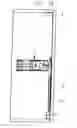
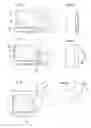
FIG. 1 shows a vertical section through a cupboard with the lid closed;
FIG. 2 shows a vertical section through the same cupboard with the lid open;
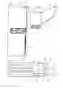
FIG. 3 shows a plan view of a support arm drive according to the invention;
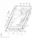
FIG. 4 shows a chart of the front region of a support arm drive according to the invention, wherein the lid and the support arm have been omitted;
FIG. 5 shows a chart of the front region of a support arm drive according to a further embodiment, wherein, once again, the lid has been omitted;
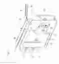
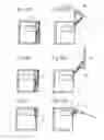
FIGS. 6 to 11 show plan views of the front region of a support arm drive with various positions of the lid, and
FIGS. 12 to 14 show various embodiments of an steering linkage for a lid in the closed and open positions of the lid respectively.
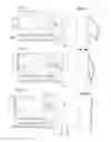
The support arm drive 1 according to the invention is attached together with the support arm 2 to a side wall 3 of a high cupboard.
The free end of the support arm 2 is hinged to a lid 4. The support arm 2 is connected in a pivotal manner to an axis 5 of the support arm drive 1. Moreover, the support arm 2 is designed as a two-arm lever with a short lever arm 6, to which a control element 7 is connected in an articulated manner via an axis 8.
The control element 7 provides a control curve 9 in the form of a convex curved web at the distal end with reference to the axis 8.
Several, preferably three, compression springs 11, which press via a pressure component 12 on the control curve 9 of the control element 7, are mounted in the housing 10 of the support arm drive 1. A height-adjustable metal plate 21, which is disposed in contact with the control curve 9, is mounted in the pressure component 12. There is no friction between the control element 7 and the metal plate 21 during the pivoting of the control element 7, because the metal plate 21 is height adjustable. The metal plate 21 can be disposed in a sliding bearing.
In the embodiment shown in FIG. 4, the control element 7 is mounted in a pivotal manner via an axis 16 on a slider 15, which is capable of linear movement.
In the embodiment according to FIG. 5, the control element 7 is mounted in a pivotal manner on the pressure component 12, and in fact by means of an axis 13, which projects through an oblong borehole 14 in the pressure component 12. As a result of the axis 13 and the oblong borehole 14, the control element 7 is mounted so that it can be pivoted and is also capable of linear movement relative to the pressure component 12.
The control curve 9 is designed in such a manner that the support arm 2 is pushed by the springs 11 into the uppermost stop position just before reaching its uppermost end stop, and into its lowest closed position just before reaching the lowest stop position. Between these two positions, there is a neutral region, in which the lid 4 is held in equilibrium.
A damper 18, which is designed in the embodiment as a linear damper, is arranged between the pressure component 12 or the slider 15, which is capable of linear movement, and a stationary stop 17 formed on the housing 10. Furthermore, the support arm 2 provides a stop 19 for the damper 18. If the lid 4 is raised, and the support arm 2 approaches the uppermost stop position, the slider 15, which is capable of linear movement, presses on the damper 18, which is supported on the other hand by the stop 17, so that the damper 18 cushions the pivotal movement of the support arm 2 within this range.
If the lid 4 is lowered, and the support arm 2 approaches its lowest stop position, the stop 19 of the support arm 2 presses on the damper 18, of which the end disposed opposite to the stop 19 is supported by the slider 15, which is capable of linear movement. In this manner, the support arm 2 is cushioned before reaching the lower stop position, that is to say, before reaching the closed position of the lid 4. Accordingly, one damper 18 is sufficient to cushion the movement of the support arm 2 for the opening and also for the closing of the lid 4.
In the illustrated embodiment, the support arm drive 1 is fitted with a single damper 18, which brakes the support arm 2 just before it reaches the closed position and also before it reaches the most extreme open position. However, two dampers 18 could also have been provided, wherein one of the dampers 18 brakes the support arm 2 when it reaches the closed position, and the second damper 18 brakes the support arm 2 when it reaches the open position. The two dampers 18 can provide different damping characteristics.
The cushioning distance and the cushioning power of the damper 18 and/or dampers 18 are advantageously adjustable.
The support arm drive 1 according to the invention is designed so that it can be attached to the left-hand side wall or to the right-hand side wall 3 of an item of furniture. The support arm drive 1 is advantageously provided with a covering cap, which can be attached optionally to the mutually-opposing flat sides of the support arm drive 1 depending on whether the support arm drive I is to be attached to the right-hand or the left-hand side wall 3 of an item of furniture.
Moreover, a further stop 20, which establishes the uppermost stop position of the support arm 2, is provided in the housing 10.
The damper 18 in the illustrated embodiment is designed as a linear damper and as a fluid damper. However, an air damper and also a hydraulic damper can also be used.
Claims
1-10. (canceled)
11. Support arm drive for cabinet lids, comprising a support arm hinged to a lid, which support arm can be pivoted through a pivotal range limited by two stop positions, and comprising at least one damper, which cushions the pivotal movement of the support arm wherein the damper cushions the pivotal movement of the support arm before the two stop positions of the support arm, wherein a neutral range, in which the movement of the support arm is not influenced by the damper, is provided between the two cushioned regions.
12. Support arm drive according to claim 11, wherein a single damper is provided, which cushions the pivotal movement of the support arm before the two stop positions of the adjusting arm.
13. Support arm drive according to claim 11, wherein a stop for the damper is provided on the support arm.
14. Support arm drive according to claim 11, wherein a control element is connected in an articulated manner to the support arm and comprises a control curve, on which at least one spring presses, wherein a pressure component capable of linear movement, which is disposed in direct contact with the control curve, is provided between the at least one spring and the control element, and wherein the damper is disposed between the pressure component and a stationary stop.
15. Support arm drive according to claim 11, wherein the control element is mounted in a pivotal manner on a slider capable of linear movement, and the damper is disposed between the slider and a stationary stop.
16. Support arm drive according to claim 11, wherein the damper is designed as a fluid damper.
17. Support arm drive according to claim 16, wherein the damper is designed as a linear damper.
18. Support arm drive according to claim 11, wherein the control curve is formed as a convex curved web at the distal end of the control element with reference to the bearing position on the support arm.
19. Support arm drive according to claim 11, wherein the support arm drive can be fitted both to a left-hand side wall and to a right-hand side wall of an item of furniture.
20. Support arm drive according to claim 19, wherein the support arm drive is provided with a covering cap, which can be attached optionally to the mutually-opposing flat sides of the support arm drive.
21. Support arm drive according to claim 11, wherein the support arm is biased by at least one spring.
Images & Drawings included:
Sources:
- United States Patent and Trademark Office - verify current appl. status at the USPTO↗
Recent applications in this class:
- » 20250052103 2025-02-13
WIRE ROPE SYSTEM - » 20250034926 2025-01-30
Control arm for movable furniture parts - » 20250027353 2025-01-23
Furniture fitting having an adjustment mechanism - » 20230272655 2023-08-31
FURNITURE DRIVE FOR MOVING A FURNITURE PART THAT IS MOVABLY MOUNTED RELATIVE TO A FURNITURE BODY - » 20220259909 2022-08-18
Fitting arrangement - » 20220112753 2022-04-14
HELICAL COMPRESSION SPRING FOR AN ACTUATOR FOR OPENING AND CLOSING A DOOR OR A TAILGATE OF A CAR - » 20220056747 2022-02-24
Furniture drive - » 20220003033 2022-01-06
SUPPORT ELEMENT FOR A MOTOR VEHICLE - » 20210270070 2021-09-02
Furniture drive - » 20200131825 2020-04-30
Control arm having adjustable length
Recent applications for this Assignee:
- » 20140319987 2014-10-30
Piece of furniture with actuating arm arrangement - » 20140300262 2014-10-09
Drive device for moveable furniture component - » 20140184047 2014-07-03
Drawer - » 20140175962 2014-06-26
Piece of furniture comprising an inner body that can be raised and lowered, and leaf for covering same - » 20140117828 2014-05-01
Drawer - » 20140077678 2014-03-20
Catching locking mechanism for pieces of furniture - » 20140077677 2014-03-20
Fastening device for mounting a front cover on a drawer - » 20140072366 2014-03-13
Fastening device for fastening a front panel on a drawer - » 20140070687 2014-03-13
Fastening device for mounting a front cover on a drawer - » 20140060991 2014-03-06
Synchronizing device for movably mounted furniture part