Method and apparatus of controlling for charge/discharge power of battery
US20060284614A1
2006-12-21
11/452,844
2006-06-14
✅ Patent granted
US 7,683,579 B2
2010-03-23
-
-
Edward Tso | M'Baye Diao
2027-03-18
Abstract:
Disclosed is an apparatus and method for controlling the discharge or charge power of a battery, capable of preventing over-charge and over-discharge of battery cells according to states of the battery cells, and solving a problem that the lifetime of a conventional battery pack is rapidly reduced due to the over-charge or over-discharge of some cells of the battery pack. The method includes the steps of estimating the maximum power of the battery, measuring voltage of a battery cell or pack, checking whether or not the voltage of the battery cell or pack deviates from a preset limited range so as to correspond to the maximum power, and when the voltage of the battery cell or pack deviates from a preset limited range, controlling the discharge or charge power of the battery.
Inventors:
- Do-Youn KIM 21 🇰🇷 Daejeon, South Korea
- Do Yang JUNG 22 🇰🇷 Hwaseong-si, South Korea
- Do Youn Kim 5 🇰🇷 Seo-gu, South Korea
Assignee:
- LG Chem, Ltd. 1,718 🇰🇷 , South Korea
Interested in similar patents?
Get notified when new applications in this technology area are published.
Classification:
H02J7/0029 » CPC main
Circuit arrangements for charging or depolarising batteries or for supplying loads from batteries with safety or protection devices or circuits
H02J7/00712 » CPC further
Circuit arrangements for charging or depolarising batteries or for supplying loads from batteries; Regulation of charging or discharging current or voltage the cycle being controlled or terminated in response to electric parameters
H02J7/0077 » CPC further
Circuit arrangements for charging or depolarising batteries or for supplying loads from batteries; Regulation of charging or discharging current or voltage using semiconductor devices only the charge cycle being terminated in response to electric parameters
G01R1/06 IPC
Details of instruments or arrangements of the types included in groups - and; General constructional details Measuring leads; Measuring probes
H02J7/00 IPC
Circuit arrangements for charging or depolarising batteries or for supplying loads from batteries
G01R31/36 IPC
Arrangements for testing electric properties; Arrangements for locating electric faults; Arrangements for electrical testing characterised by what is being tested not provided for elsewhere Arrangements for testing, measuring or monitoring the electrical condition of accumulators or electric batteries, e.g. capacity or state of charge [SoC]
G01N27/416 IPC
Investigating or analysing materials by the use of electric, electrochemical, or magnetic means by investigating electrochemical variables; by using electrolysis or electrophoresis Systems
Description
This application claims the benefit of the filing date of Korean Patent Application No. 2005-50972, filed on Jun. 14, 2005, in the Korean Intellectual Property Office, the disclosure of which is incorporated herein in its entirety by reference.
TECHNICAL FIELDThe present invention relates to a method for controlling a power limit according to states of battery cells in order to prevent over-charge and over-discharge of the battery cells used in hybrid electric vehicles (HEVs).
BACKGROUND ARTIn general, hybrid electric vehicles (HEVs) are mounted with a battery pack in which several tens of battery cells are connected in series. The maximum available charge and discharge powers of the battery pack are controlled on the basis of a state of charge (SOC) and temperature of the battery pack. An example of determining the maximum available charge and discharge powers of the battery pack will be described below on the basis of conventional charge and discharge control using characteristic modeling of the battery constituted of charge and discharge internal resistances.
First, since the internal resistances of the battery pack are changed depending on the SOC and temperature of the battery pack, they are measured at each temperature for each SOC through a test. In a method of measuring the internal resistances, when current flows through the battery pack, a value dividing a variation of voltage by the current is determined as a value of internal resistance. The obtained internal resistance value is stored in a memory. Real power of the battery pack is estimated through the internal resistance according to Equation (1). P = I × Δ V = Δ V R × Δ V = Δ V 2 R Δ V = V LIMIT - V CURRENT ( 1 )
In Equation (1), the negative value becomes discharge power, but the positive value becomes charge power. Further, the internal resistance R is to call up the internal resistance value stored in the memory according to the SOC and temperature of each state, and then substitute the internal resistance value into the Equation (1).
Meanwhile, each battery cell has the same performance when initially mounted to a vehicle, and thus the power of a motor for the vehicle is controlled on the basis of the maximum power of the battery pack.
However, as mileage of the vehicle increases, performance deviation is generated between the battery cells. Nevertheless, when charging and discharging processes continue to be performed on the basis of the maximum power of the battery pack, some battery cells are charged or discharged in excess of available charge or discharge power, as shown in FIG. 1.
In this manner, because the power of the vehicular motor is controlled on the basis of the maximum power of the battery pack, some degraded battery cells are over- charged or over-discharged during operation of the vehicle. This results in acceleration of the performance deviation between the battery cells, thereby sharply reducing a lifetime of the battery pack.
DISCLOSURE OF THE INVENTIONTherefore, the present invention has been made in view of the above-mentioned problems, and it is an objective of the present invention to provide an apparatus and method capable of preventing over-charge and over-discharge of battery cells according to states of the battery cells in order to solve a problem that the lifetime of a conventional battery pack is rapidly reduced due to the over-charge or over-discharge of some cells of the battery pack.
According to an aspect of the present invention, there is provided a method for controlling the discharge or charge power of a battery. The method includes the steps of estimating the maximum power of the battery, measuring voltage of a battery cell or pack, checking whether or not the voltage of the battery cell or pack deviates from a preset limited range so as to correspond to the maximum power, and when the voltage of the battery cell or pack deviates from a preset limited range, controlling the discharge or charge power of the battery.
BRIEF DESCRIPTION OF THE DRAWINGSFIG. 1 is a graph showing a case where over-charge and over-discharge take place at a battery cell.
FIGS. 2 and 3 illustrate characteristics of charge power and discharge power according to temperature and a state of charge (SOC).
FIG. 4 illustrates a characteristic of a degradation rate of a battery.
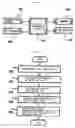
FIG. 5 illustrates a construction of a battery control apparatus according to an exemplary embodiment of the present invention.
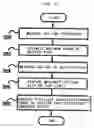
FIGS. 6 and 8 are flowcharts of a method for controlling the discharge or charge power of a battery pack according to the present invention.
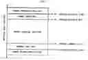
FIG. 7 schematically illustrates available voltage of each cell in a battery pack by sections.
BEST MODE FOR CARRYING OUT THE INVENTIONReference will now be made in detail to the exemplary embodiments of the present invention.
The present invention estimates the maximum power of a battery, and adjusts charge and discharge power of the battery using the estimated maximum power- and voltage of the battery.
First, a description will be made regarding a process of deriving a calculation formula for estimating the maximum power of the battery according to an exemplary embodiment of the present invention.
A tester extracts the maximum charge and discharge power of the battery depending on a state of charge (SOC) of at least one battery by which a vehicle can be driven, and then detects the correlation between the SOC and the maximum charge and discharge power.
Subsequently, the tester extracts the maximum power of the battery at a plurality of temperatures at which the vehicle can be driven, and then detects the correlation between the maximum power and the temperature. The tester extracts a degradation rate of the power of the battery depending on the discharge of the battery while the vehicle travels, and detects the correlation between the degradation rate and the discharge.
The charge power and the discharge power are expressed according to the temperature and SOC as in graphs of FIGS. 2 and 3. Thus, the power at a certain temperature can be approximated by Equation (2).
Power=C0+C1SOC1+C2*SOC2+C3*SOC3+C4*SOC4+C5*SOC5 (2)
In Equation (2), Cx is the constant, and SOCx refers to SOC to the x-th power. Cx=F(temp)x, and is determined by temperature.
Cx can be approximated by Equation (3).
Cx=F(temp)x=D0+D1*temp1+D2*temp2 (3)
In Equation (3), Dx is the invariable constant, and tempx refers to temp to the x-th power.
The charge power and the discharge power can express the maximum power Powermax of the battery from the correlation between temperature and SOC, as in Equation (4). Power max = F ( SOC , temp , accumulated discharge Ah ) = F ( SOC , temp ) × F ( accumulated discharge Ah ) ( 4 )
In Equation (4), F(accumulated discharge Ah) indicates the degradation rate of the battery according to the traveling of the vehicle.
Generally, the battery is degraded in proportion to its quantity of use. This has a characteristic as shown in FIG. 4. This characteristic is named a degradation rate of the battery. The degradation rate of the battery is approximated by Equation (5).
F(accumulated discharge Ah)=C5k5+C4k4+C3k3+C2k2+C1k+C0
In Equation (5), C5 through C0 are the constant, and k is within the range of [0, 300000] and is changed into and input as a value of the range of [−1, 1] when it is input into the function as an input value.
An example of calculating the degradation rate according to Equation (5) is as follows: F(accumulated discharge Ah)=−16.3986k5+15.0026k4+13.3074k3−8.38689k2−7.96289k+82.3028.
Therefore, the maximum power of the battery can be approximated by Equation (6) below.
Powermax={F(temp)5×SOC5+F(temp)4×SOC4+F(temp)3×SOC3+F(temp)2×SOC2+F(temp)1×SOC+F(temp)0}×(C5k5+C4k4+C3k3+C2k2+C1k+C0)
Now, an exemplary embodiment of the present invention will be described, in which the maximum power of the battery is estimated according to Equation 6, and the charge power and discharge power of the battery are adjusted using the estimated maximum power and voltage of the battery.
First, a construction of a battery control apparatus to which the present invention can be applied will be described with reference to FIG. 5.
A controller 100 performs a process of adjusting the charge and discharge power of a battery according to an exemplary embodiment of the present invention. In order words, the controller 100 estimates the maximum power of the battery in consideration of temperature, SOC, and a degradation rate according to Equation 6, measures voltage of the battery, and adjusts the charge and discharge power of the battery using the maximum power and the voltage of the battery.
A memory 102 stores various pieces of information including a processing program of the controller 100, and particularly information on a voltage limit of the battery cell or pack which corresponds to the maximum power of each battery according to an exemplary embodiment of the present invention.
A voltmeter 104 measures the voltage of the corresponding battery pack or cell, and provides the result to the controller 100.
A temperature sensor 106 measures temperature, and provides the result to the controller 100.
A SOC estimator 108 estimates an SOC of the corresponding battery, and provides the result to the controller 100.
Now, a method applicable to the battery control device according to an exemplary embodiment of the present invention will be described in detail.
Further, a method of using the voltage measured from the battery cell will be described with reference to FIG. 6.
The controller 100 measures temperature and SOC by means of the temperature sensor 106 and the SOC estimator 108, and estimates the maximum power of the battery pack according to Equation 6 (S200 and S202).
Thereafter, the controller 100 measures voltage of the battery cell by means of the voltmeter 104 (S204).
When the voltage of the battery cell is measured, the controller 100 compares a voltage limit corresponding to the estimated maximum power of the battery which is pre-stored in the memory 102 with the measured voltage limit of the battery cell (S206). When at least one of the measured voltage limits is higher than the preset voltage limit, the controller decreases available charge and discharge power of the battery pack. In contrast, when at least one of the measured voltage limits is lower than the preset voltage limit, the controller increases the available charge and discharge power of the battery pack (S208). Increase and decrease widths of the available charge and discharge power can be determined in advance, and preferably within a range of about 2 to 10%.
For more description, available voltages of the battery cells in the battery pack are denoted by sections in FIG. 7. The available voltages are for safety and lifetime of the battery cells during operation. As shown, the available voltages of the battery pack, for example, available from LG Company have a range of 2.5V to 4.3V. The range is varied depending on company, battery type, and battery version.
When charged with the estimated power of the battery, the controller 100 decreases the charge power if the cell voltage is higher than 4.3V, and increases the charge power if the cell voltage is lower than 4.2V. In contrast, when discharged, the controller 100 decreases the discharge power if the cell voltage is lower than 2.5V, and increases the discharge power if the cell voltage is higher than 2.8V.
At this time, according to an exemplary embodiment of the present invention, the power increase and decrease widths during charging and discharging are controlled within a range of 2 to 10%.
In this manner, when the battery cell voltage deviates from the voltage limit during charging or discharging, the power of the battery is adjusted to that deviation. If the battery cells connected in series are well balanced, and the SOC and temperature are accurately measured, the cell voltage does not exceed the available value within the estimated power during charging. Nevertheless, if the battery cell voltage exceeds the voltage limit, this can be determined that the power estimation goes wrong due to a certain factor. When the battery cell voltage continues to exceed the voltage limit, detonation or fire may take place. Hence, the controller decreases the power of the battery, thereby decreasing the battery cell voltage below the voltage limit.
Another method of using the measured voltage of the battery cell will be described with reference to FIG. 8.
The controller 100 measures temperature and SOC by means of the temperature sensor 106 and the SOC estimator 108, and estimates the maximum power of the battery pack according to Equation 6 (S300 and S302).
Thereafter, the controller 100 measures voltage of the battery pack by means of the voltmeter 104 (S304).
When the voltage of the battery pack is measured, the controller 100 compares a voltage limit of the battery pack which is pre-stored in the memory 102 with the measured voltage of the battery pack (S306). If the measured voltage is higher than the voltage limit corresponding to the estimated maximum power of the battery, the controller decreases available charge and discharge power of the battery pack. In contrast, if the measured voltage is lower than the voltage limit, the controller increases available charge and discharge power of the battery pack (S308). Increase and decrease widths of the available charge and discharge power can be determined in advance, and preferably within a range of about 2 to 10%.
INDUSTRIAL APPLICABILITYAs can be seen from the foregoing, according to the present invention, when the battery pack for the HEVs having the method of preventing over-charge and over-discharge causes a performance difference between its cells by using it for a time longer than a predetermined time, it can control its power on the basis of the battery cells having low performance, so that the over-charge and over-discharge of the battery cells can be prevented. Thus, it is possible to prevent sharp degradation of the battery due to the over-charge and over-discharge of the battery cells, and to increase the lifetime of the battery pack.
While this invention has been described in connection with what is presently considered to be the most practical and exemplary embodiment, it is to be understood that the invention is not limited to the disclosed embodiment and the drawings, but, on the contrary, it is intended to cover various modifications and variations within the spirit and scope of the appended claims.
Claims
1. A method for controlling the discharge or charge power of a battery, the method comprising the steps of:
estimating the maximum power of the battery;
measuring voltage of a battery cell or pack;
checking whether or not the voltage of the battery cell or pack deviates from a preset limited range so as to correspond to the maximum power; and
when the voltage of the battery cell or pack deviates from a preset limited range, controlling the discharge or charge power of the battery.
2. The method according to claim 1, wherein the maximum power of the battery is calculated by a following equation approximated from the correlation between: a state of charge (SOC) of the battery, and the maximum charge and discharge power of the battery; and temperature, and the maximum power of the battery,
Power max = F ( SOC , temp , accumulated discharge Ah ) = F ( SOC , temp ) × F ( accumulated discharge Ah ) .
3. The method according to claim 1, wherein the step of controlling the discharge or charge power of the battery comprises the sub-steps of:
when at least one of the measured voltages is higher than the voltage of the preset limited range, decreasing available charge and discharge power of the battery pack; and
when at least one of the measured voltages is lower than the voltage of the preset limited range, increasing the available charge and discharge power of the battery pack.
4. A battery control apparatus comprising:
a temperature sensor;
a state of charge (SOC) estimator for estimating an SOC of a battery;
a voltmeter for measuring voltage of a battery cell or pack; and
a controller for:
estimating the maximum power of the battery using the temperature and the SOC;
measuring the voltage of the battery cell or pack by means of the voltmeter;
checking whether or not the voltage of the battery cell or pack deviates from a preset limited range so as to correspond to the maximum power; and
when the voltage of the battery cell or pack deviates from a preset limited range, controlling discharge or charge power of the battery.
5. The battery control apparatus according to claim 4, wherein the maximum power of the battery is calculated by a following equation approximated from the correlation between: the SOC of the battery, and the maximum charge and discharge power of the battery; and the temperature, and the maximum power of the battery,
Powermax=F(SOC,temp,accumulated discharge Ah)F(SOC,temp)×F(accumulated discharge Ah).
6. The battery control apparatus according to claim 4, wherein the controlling of the discharge or charge power of the battery is performed by:
when at least one of the measured voltages is higher than the voltage of the preset limited range, decreasing available charge and discharge power of the battery pack; and
when at least. one of the measured voltages is lower than the voltage of the preset limited range, increasing the available charge and discharge power of the battery pack.
Images & Drawings included:


Sources:
- United States Patent and Trademark Office - verify current appl. status at the USPTO↗
Recent applications in this class:
- » 20250286389 2025-09-11
DEVICE FOR GENERATING A VIRTUAL NEUTRAL POINT - » 20250279660 2025-09-04
POWER SUPPLY APPARATUS, POWER SUPPLY SYSTEM, AND VEHICLE - » 20250260245 2025-08-14
BATTERY STRING PRE-CHARGE OPERATION - » 20250253685 2025-08-07
ENERGY STORAGE SYSTEM AND EQUIPOTENTIAL APPARATUS THEREOF, ENERGY STORAGE DEVICE, AND POWER STATION - » 20250253684 2025-08-07
BATTERY HEALTH PROTECTION IN FAST-CHARGING LITHIUM ION (Li-ion) BATTERY CHARGING SYSTEMS - » 20250253683 2025-08-07
ANALYSIS OF BATTERY CELLS DURING SWITCHED-MODE CONVERSION IN NORMAL OPERATION - » 20250246919 2025-07-31
PROTECTION CIRCUIT AND CHARGING EQUIPMENT - » 20250239870 2025-07-24
Vehicle Charging Circuit With A Two-Stage Discharge Process Via A DC-DC Converter And A Passive Discharge Circuit - » 20250219428 2025-07-03
SECONDARY BATTERY PROTECTION CIRCUIT, SECONDARY BATTERY PROTECTION DEVICE AND BATTERY DEVICE ABOUT TRANSITION TO LOW POWER MODE - » 20250211002 2025-06-26
PROTECTION CIRCUIT AND CHARGING DEVICE
Recent applications for this Assignee:
- » 20230408872 2023-12-21
Optical device - » 20230236160 2023-07-27
Method for evaluating properties of melt-blown plastic resin - » 20220162351 2022-05-26
Catalyst composition, cleaning liquid composition containing the same, and method of cleaning polymerization apparatus using the cleaning liquid composition - » 20220085292 2022-03-17
Organic light emitting device - » 20210388239 2021-12-16
Acrylic emulsion pressure sensitive adhesive composition - » 20210284607 2021-09-16
Heterocyclic compound and organic light emitting device comprising the same - » 20210230417 2021-07-29
Vinyl alcohol based copolymer, method for preparing the same and gas barrier film comprising the same - » 20210230323 2021-07-29
Polyethylene and chlorinated polyethylene thereof - » 20210218012 2021-07-15
Positive electrode having lithium transition metal oxide containing nickel, cobalt and manganese for secondary battery and secondary battery including the same - » 20210215661 2021-07-15
Method for evaluating properties of polypropylene resin, method for preparing polypropylene non-woven fabric, and polypropylene non-woven fabric