Joint construction in a laminate of metal and plastic layer
US20070116906A1
2007-05-24
11/655,879
2007-01-22
✅ Patent granted
US 7,527,846 B2
2009-05-05
-
-
Jane Rhee
2027-11-01
Abstract:
A joint construction in a laminate of, alternately, at least two metal layers and at least one plastic layer accommodated between them comprises metal layers which each have at least two sections. The two sections of at least one outer metal layer overlap one another and are fixed to one another at the location of the overlap by means of an adhesive. Each metal layer has overlapping sections which are fixed to one another by an adhesive.
Assignee:
- FOKKER AEROSTRUCTURES B. V. 1 🇳🇱 PAPENDRECHT, Netherlands
Interested in similar patents?
Get notified when new applications in this technology area are published.
Classification:
B32B15/08 » CPC main
Layered products comprising a layer of metal comprising metal as the main or only constituent of a layer, next to another layer of a of synthetic resin
Y10T428/18 » CPC further
Stock material or miscellaneous articles Longitudinally sectional layer of three or more sections
Y10T428/187 » CPC further
Stock material or miscellaneous articles; Longitudinally sectional layer of three or more sections; Next to unitary sheet of equal or greater extent Continuous sectional layer
Y10T428/19 » CPC further
Stock material or miscellaneous articles Sheets or webs edge spliced or joined
Y10T428/192 » CPC further
Stock material or miscellaneous articles; Sheets or webs edge spliced or joined Sheets or webs coplanar
Y10T428/195 » CPC further
Stock material or miscellaneous articles; Sheets or webs edge spliced or joined; Sheets or webs coplanar Beveled, stepped, or skived in thickness
Y10T428/197 » CPC further
Stock material or miscellaneous articles; Sheets or webs edge spliced or joined; Sheets or webs coplanar with noncoplanar reinforcement
Y10T428/2991 » CPC further
Stock material or miscellaneous articles; Coated or structually defined flake, particle, cell, strand, strand portion, rod, filament, macroscopic fiber or mass thereof; Particulate matter [e.g., sphere, flake, etc.] Coated
F16B5/07 IPC
Joining sheets or plates, e.g. panels, to one another or to strips or bars parallel to them by means of multiple interengaging protrusions on the surfaces, e.g. hooks, coils
F16B5/10 IPC
Joining sheets or plates, e.g. panels, to one another or to strips or bars parallel to them by means of bayonet connections
B32B3/00 IPC
Layered products comprising a layer with external or internal discontinuities or unevennesses, or a layer of non-planar form ; Layered products having particular features of form
Description
This application is a continuation of co-pending application Ser. No. 10/275,890, filed on Jun. 6, 2003. Application Ser. No. 10/275,890 is the national phase of PCT International Application No. PCT/NL01/00353 filed on May 9, 2001 under 35 U.S.C. § 371, which claims priority of Dutch Application No. 1015141 filed May 9, 2000. The entire contents of each of the above-identified applications are hereby incorporated by reference.
The invention relates to a joint construction in a laminate of, alternately, at least two metal layers and at least one plastic layer incorporated between them, which metal layers each comprise at least two sections and the two sections of at least one outer metal layer overlap one another, which two sections are fixed to one another at the location of the overlap by means of an adhesive.
A joint construction of this type is disclosed in EP-A 983 141. This known joint construction has three metal layers, between which two plastic layers are accommodated. One of the outer metal layers has two sections which overlap one another in such a way that a smooth surface is obtained. The spaces next to the overlap are filled with the glue by means of which the overlapping parts of the sections are fixed to one another.
The other metal layers and the plastic layers continue on at the location of the overlap. These other metal layers also consist of two sections, the leading edges of which abut one another. The outer layer thereof is provided with a glued fixing strip at the location of the leading edges, which fixing strip, together with the plastic layer located on the other side of the sections, must provide for the transfer of force between said sections.
This known joint construction has a number of disadvantages. First of all the seam between the sections with leading edges abutting one another must have fairly accurately prescribed dimensions. This means that the sections themselves must have fairly accurate dimensions and also that the sections must be positioned accurately with respect to one another. A further disadvantage is that an additional joining strip has to be applied to one of the free sides of the joint construction. For these reasons a joint construction of this type is relatively inconvenient and expensive.
The aim of the invention is to provide a joint construction of the type described above that can be produced more simply. Said aim is achieved in that each metal layer has overlapping sections which are fixed to one another by means of an adhesive.
In the case of the joint construction according to the invention all sections can be produced and positioned with respect to one another with wide tolerance. The cost can consequently remain relatively low, without, however, this leading to inaccuracies or insufficient strength.
In this context the joint construction can be so constructed that the overlap between two sections of a metal layer is offset with respect to the overlap between two sections of another metal layer.
The outside of the joint construction is continuous and smooth if, in each metal layer, one section is straight and the other section is joggled. Such an embodiment is important when the joint construction is used in panels for aircraft and the like.
The invention will be explained in more detail below with reference to an illustrative embodiment shown in the figure.
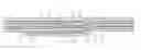
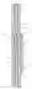
The figure shows a cross-section through a joint construction according to the invention. This joint construction comprises three metal layers 1-3, each of which consists of two sections 4′, 5′; 4″, 5″; 4″′, 5″′. Two layers of plastic material 6, 7, which, for example, consist of a matrix of glass fibres embedded in a resin, are arranged between the metal layers 1-3 The sections 4′-5″′ of each of the layers 1-3 overlap one another at the location of an overlap 8 to 10. For this purpose the one section 4′ of the outer metal layer 1 has a section 11 that is joggled on and extends to below the other section 5′. The sections 4′ and 5′ are glued to one another at the location of the overlap 8 by means of a layer 12 of glue.
For the sections 4″, 4″′ of the other layers 2, 3 it is also the case that the section 11 thereof is joggled and extends to below the other section 5″, 5″′ of said metal layer 2 or 3, respectively.
The plastic layers 6, 7 run through continuously at the location of the overlap 8-10.
Claims
1-13. (canceled)
14. A joint structure in a laminate comprising:
a first, outermost metal layer comprising first and second separate sections having outer surfaces arranged to be generally continuous with one another, the first section having an edge portion bent out of alignment with both the second section and a remainder of the first section, the edge portion of the first section overlapping and being glued to an inner surface of the second section at the joint structure;
a first layer of plastic material in direct contact with inner surfaces of the first and second sections of the outermost metal layer; and
a second metal layer comprising third and fourth separate sections, the third section having an edge portion bent out of alignment with both the fourth section and a remainder of the third section, the edge portion of the third section overlapping and being glued to an inner surface of the fourth section at the joint structure, the second metal layer being in direct contact with the first plastic layer.
15. The joint structure of claim 14, further comprising:
a second layer of plastic material in direct contact with inner surfaces of the third and fourth sections of the second metal layer; and
a third metal layer comprising fifth and sixth separate sections, the fifth section having an edge portion bent out of alignment with a remainder of the fifth section and the sixth section, the edge portion of the fifth section overlapping and being glued to an inner surface of the sixth section at the joint structure, the third metal layer being in direct contact with the second plastic layer.
16. The joint structure of claim 14, wherein the first layer of plastic material is uninterrupted at the joint structure.
17. The joint structure of claim 16, wherein the plastic material is a matrix of glass fibres embedded in a resin.
18. The joint structure of claim 16, wherein the overlapping edge portion of the first metal layer is staggered with respect to the overlapping edge portion of the second metal layer, so that no said overlapping edge portion lies directly above any other said overlapping edge portion within the joint structure.
19. The joint structure of claim 18, wherein the plastic material is a matrix of glass fibres embedded in a resin.
20. The joint structure of claim 15, wherein the first and second layers of plastic material are uninterrupted at the joint structure.
21. The joint structure of claim 20, wherein the overlapping edge portions of the first, second, and third metal layers are staggered with respect to one another, so that no said overlapping edge portion lies directly above any other said overlapping edge portion within the joint structure.
22. The joint structure of claim 21, wherein the plastic material is a matrix of glass fibres embedded in a resin.
23. The joint structure of claim 20, wherein the plastic material is a matrix of glass fibres embedded in a resin.
24. The joint structure of claim 14, wherein the overlapping edge portion of the first metal layer is staggered with respect to the overlapping edge portion of the second metal layer, so that no said overlapping edge portion lies directly above any other said overlapping edge portion within the joint structure.
25. The joint structure of claim 24, wherein the plastic material is a matrix of glass fibres embedded in a resin.
26. The joint structure of claim 15, wherein the overlapping edge portions of the first, second, and third metal layers are staggered with respect to one another, so that no said overlapping edge portion lies directly above any other said overlapping edge portion within the joint structure.
27. The joint structure of claim 26, wherein the plastic material is a matrix of glass fibres embedded in a resin.
28. The joint structure of claim 14, wherein the plastic material is a matrix of glass fibres embedded in a resin.
29. The joint structure of claim 15, wherein the plastic material is a matrix of glass fibres embedded in a resin.
Images & Drawings included:
Sources:
- United States Patent and Trademark Office - verify current appl. status at the USPTO↗
Recent applications in this class:
- » 20250269627 2025-08-28
LAMINATE - » 20250236093 2025-07-24
METHOD OF PRODUCING THERMALLY CONDUCTIVE SHEET - » 20250236092 2025-07-24
SULFONATED THERMOPLASTIC PART AND METHOD FOR FORMING SAME - » 20250229507 2025-07-17
MULTILAYER ARTICLE COMPRISING METAL, THERMALLY CONDUCTIVE HYBRID, AND THERMALLY CONDUCTIVE CONTINUOUS FIBER COMPOSITE - » 20250153461 2025-05-15
ELECTROMAGNETIC INTERFERENCE SHIELDING FILM AND PREPARING METHODS THEREOF - » 20250121586 2025-04-17
LAMINATED BODY HAVING RESIN LAYER AND METAL LAYER AND PRODUCTION METHOD FOR SAME - » 20250108583 2025-04-03
COMPOSITE MATERIAL, APPLICATIONS THEREOF, AND METHOD FOR PRODUCING BASE MATERIAL TO WHICH POLYDOPAMINE IS ADHERED - » 20250108582 2025-04-03
RESIN COMPOSITION, PREPREG, FILM WITH RESIN, SHEET OF METAL FOIL WITH RESIN, METAL-CLAD LAMINATE, AND PRINTED WIRING BOARD - » 20250042134 2025-02-06
SHIELDED CEILING TILE - » 20250042133 2025-02-06
Temperature-adaptive radiative coating for all-season building thermal regulation