Multi symbol bit detection for SDPSK signals
US20070118785A1
2007-05-24
11/478,271
2006-06-29
✅ Patent granted
US 7,487,411 B2
2009-02-03
-
-
David Ton
2027-07-13
Abstract:
This invention discloses a method of accurately detecting the current bit in a SDPSK modulated signal at the receiver. The proposed method calculates the current bit from the past-detected bits and the past symbols. Each past symbol estimates the current bit. Each of these estimates is summed up to provide the final estimate of the bit. The proposed method for the reception of SDPSK modulated data improves the bit error rate performance. The proposed method can be applied in any communication system that uses SDPSK modulation.
Assignee:
- MobiApps, Inc. 3 🇺🇸 Arlington, VA, United States
Interested in similar patents?
Get notified when new applications in this technology area are published.
Classification:
H03M13/00 IPC
Coding, decoding or code conversion, for error detection or error correction; Coding theory basic assumptions; Coding bounds; Error probability evaluation methods; Channel models; Simulation or testing of codes
H04L27/22 » CPC main
Modulated-carrier systems; Phase-modulated carrier systems, i.e. using phase-shift keying Demodulator circuits; Receiver circuits
G06F11/08 IPC
Error detection; Error correction; Monitoring; Responding to the occurrence of a fault, e.g. fault tolerance Error detection or correction by redundancy in data representation, e.g. by using checking codes
G06F11/00 IPC
Error detection; Error correction; Monitoring
H04L1/00 IPC
Arrangements for detecting or preventing errors in the information received
G06F11/30 IPC
Error detection; Error correction; Monitoring Monitoring
G08C25/00 IPC
Arrangements for preventing or correcting errors; Monitoring arrangements
H04L27/233 IPC
Modulated-carrier systems; Phase-modulated carrier systems, i.e. using phase-shift keying; Demodulator circuits; Receiver circuits using non-coherent demodulation
Description
BACKGROUND OF THE INVENTIONThe proposed invention, in general, relates to the demodulation of a symmetrical differential phase shift keying (SDPSK) modulated signal, and specifically relates to an improved method of bit error rate (BER) detection in a SDPSK modulated signal.
The method disclosed in this invention is a technique of improving the BER for the detection of SDPSK modulated signals. The current methods in the art do not yield accurate measurements of BER in SDPSK modulated systems. The method disclosed in this invention gives the same BER at a reduced signal to noise ratio (SNR). The method of improving the detection of SDPSK modulated signals, disclosed herein, can be applied to any communication system using SDPSK modulation.
In the current art for BER estimation in SDPSK modulated signals, the immediate previous bit is used to detect the current bit.
SUMMARY OF THE INVENTIONThe proposed invention discloses a method for accurately detecting the current bit in a SDPSK modulated signal at the receiver. The proposed method calculates the current bit from the past-detected bits and the past symbols. Each past symbol estimates the current bit. Each of these estimates is summed up to provide the final estimate of the current bit.
The proposed method for the detection of SDPSK modulated bits improves the bit error rate performance. For example, if the system has a bit error rate of 0.01 at a signal to noise ratio (SNR) of say 6 dB, then the proposed method will achieve a bit error rate of 0.01 at a SNR of 5.4 dB.
One advantage of the proposed method is the improvement in bit error rate (BER) performance.
Another advantage of the proposed method is that, it can be applied to any communication system that uses SDPSK modulation.
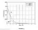
BRIEF DESCRIPTION OF THE DRAWINGSFIG. 1A illustrates the graphical representation of bit error rate versus signal to noise ratio at depth 4 and depth 0.
FIG. 1B illustrates the graphical representation of bit error rate versus signal to noise ratio at depth 5 and depth 0.
FIG. 1C illustrates the graphical representation of bit error rate versus signal to noise ratio at depth 10 and depth 0.
DETAILED DESCRIPTION OF THE INVENTIONThe method used in this invention considers all previous symbols and bits for the estimation of a current bit in the detection of the symmetrical differential phase shift keying (SDPSK) modulated signal.
The SDPSK modulation scheme is represented by the equation:
Sn=Sn-1*e(j*Π*bn/2)
where Sn is the current modulated symbol
Sn-1 is the previous modulated symbol
bn is the current bit (bn=1 for bit 1, bn=−1 for bit 0)
where j=√−1 and Π is a transcendental number, equal to approximately 3.142 . . .
The equations listed below substitute Sn-1 for four recursive expressions. By way of example, only four recursive expressions are shown to explain this invention. In actual practice, any number of recursive expressions can be used. Larger the number of recursive expressions used, greater is the improvement in BER performance.
Sn=Sn-1*e(j*Π*bn/2)
Sn=Sn-2*e(j*Π*bn/2)*e(j*Π*bn−1/2)
Sn=Sn-3*e(j*Π*bn/2)*e(j*Π*bn−1/2)*e(j*Π*bn−2/2)
Sn=Sn-4*e(j*Πbn/2)*e(j*Π*bn−1/2)*e(j*Π*bn−2/2)*e(j*Π*bn−3/2)
Similarly, Sn can be derived as a function of any of the previous bits. The following four equations are derived from the above four equations respectively.
e(j*Π*bn/2)=Sn*conj(Sn-1) (a)
e(j*Π*bn/2)=Sn*conj(Sn-2)*e(j*Π*bn−1/2) (b)
e(j*Π*bn/2)=Sn*conj(Sn-3)*e(j*Π*bn−1/2)*e(j*Π*bn−2/2) (c)
e(j*Π*bn/2)=Sn*conj(Sn-r)*e(j*Π*bn−1/2)*e(j*Π*bn−2/2)*e(j*Π*bn−(r−1)/2) (d)
Applying Eulers theorem to the equation e(j*Π*bn/2)=Sn*conj(Sn−1), we derive:
Cos (Π/2.bn)+j Sin (Π/2.bn)=Sn*conj(Sn-1)
Applying Eulers theorem and summing the left hand side and right hand side of equations (a), (b), (c) and (d),
(Cos(Π/2.bn)+j Sin(Π/2.bn))*r=Sn*conj(Sn-1)+Sn*conj(Sn-2)*e(j*Π*bn−1/2)+ . . . +Sn*conj(Sn-2)*e(j*Π*bn−(r−1)/2)) (e)
bn can assume only one of the two values, viz. −1 or +1.
Therefore, for bn=1, Cos (Π/2.bn)=0 and Sin (Π/2 bn)=r
and for bn=−1, Cos (Π/2.bn)=0 and Sin (Π/2 bn)=−r
The imaginary part on the left side should be equal to the imaginary part on the right side of equation (e), while the real part on the left side should be equal to the real part on the right side.
Sign of the imaginary part on the left side should be equal to the sign of the imaginary part on the right side of the equation (e).
Hence, bn is given by the sign of the imaginary part on the right hand side of equation (2)
bn=sign(imag(Sn*conj(Sn-1)+ . . . +Sn*conj(Sn-(r-1))))
It can be observed from the above equations that multiple estimates for bn can be derived.
The sum of all the above estimates provides an accurate assessment of the current bit bn, represented by the following equation:
bn—estimated=[Sn*conj(Sn-1)+Sn*conj(Sn-2)*e(j*Π*bn-1/2)+Sn*conj(Sn-3)*e(j*Π*bn-1/2)*e(j*Π*bn-2/2)+Sn*conj(Sn-4)*e(j*Π*bn-1/2)*e(j*Π*bn-2/2)*e(j*Π*bn−3/2)]
The current bit is calculated by the formula:
Bit=sign(imag(bn—estimated))
wherein, sign (x)=1 if x>0 and sign (x)=−1 if x<0
imag(x) is the imaginary part of the complex number x.
FIG. 1A illustrates the graphical representation of bit error rate versus signal to noise ratio in depth 4 by implementing the method presented in this invention. Depth is the number of past bits that are used to estimate the current bit. From the graph, it is found that the plots for depth 0 101 and depth 4 102 at an SNR of 6 dB, the bit error rates are approximately 0.009 and 0.006 respectively.
FIG. 1B illustrates the graphical representation of bit error rate versus signal to noise ratio in depth 5 by implementing the method presented in this invention. From the graph, it is found that the plots for depth 0 101 and depth 5 103 at an SNR of 6 dB, the bit error rates are approximately 0.009 and 0.0055 respectively.
FIG. 1C illustrates the graphical representation of bit error rate versus signal to noise ratio in depth 10 by implementing the method presented in this invention. From the graph, it is found that the plots for depth 0 101 and depth 10 104 at an SNR of 6 dB, the bit error rates are approximately 0.009 and 0.005 respectively.
It is observed from FIG. 1A, FIG. 1B and FIG. 1C that as the depth increases, i.e., as the number of past bits used in BER estimation is increased, the BER performance improves progressively.
Claims
1. A method of detecting the current bit in a symmetrical differential phase shift keying modulated signal, comprising the steps of:
calculating said current bit symbol Sn using the recursive expression
Sn=Sn-r*e(j*Π*bn/2)*e((j*Π*bn−1)/2) . . . e(j*Π*bn-(r-i/2)
e(j*Π*bn/2)=Sn*conj(Sn-r)*e(j*Π*bn−1/2)*e(j*Π*bn−2/2)*e(j*Π*bn−(r−i)/2)
wherein r is the number of past bits used for the detection of the current bit, Sn-r is the rth past symbol, bn is the current bit and Sn is the current symbol and n is the sequence index, j is the square root of −1;
calculating the summation of all the r estimated bits using the equation
bn—estimated=[Sn*conj(Sn-1)+Sn*conj(Sn−2)*e(j*Π*bn−i/2)+Sn*conj(Sn-3)*e(j*Π*bn−1/2)
*e(j*Π*bn−2/2)+ . . . +Sn*conj(Sn-r)*e(j*Π*bn−1/2)*e(j*Π*bn−2/2)* . . . *e(j*Π*bn−3/2)]
wherein bn—estimated is the current estimated bit; and
determining said current bit using the formula
bit=sign (imag(bn—estimated)).
Images & Drawings included:


Sources:
- United States Patent and Trademark Office - verify current appl. status at the USPTO↗
Recent applications in this class:
- » 20250286760 2025-09-11
PHASE-MULTIPLEXED QUADRATURE RECEIVER - » 20230379200 2023-11-23
Methods and apparatus for demodulating digital signals - » 20230370313 2023-11-16
METHODS AND APPARATUS FOR PHASE CHANGE DETECTION USING A RESONATOR - » 20230224199 2023-07-13
Phasor IQ demodulation - » 20230164011 2023-05-25
Method and device for applying subcarrier-specific phase rotation to broadband in wireless LAN system - » 20230132352 2023-04-27
Wireless network and phase control - » 20230114670 2023-04-13
Method and transmitter for constant envelope phase modulation and demodulation - » 20230006871 2023-01-05
LOW-RESOLUTION, LOW-POWER, RADIO FREQUENCY RECEIVER - » 20220353119 2022-11-03
Methods and apparatus for demodulating digital signals - » 20220166655 2022-05-26
Low-resolution, low-power, radio frequency receiver
Recent applications for this Assignee:
- » 20070168407 2007-07-19
SNR estimation using filters - » 10443537 2006-09-19
RF ASIC for subscriber communicator