Land grid array connector with cover member
US20070155215A1
2007-07-05
11/647,028
2006-12-27
✅ Patent granted
US 7,387,523 B2
2008-06-17
-
-
Hien Vu
2026-12-27
Abstract:
An LGA electrical connector (100) includes an insulative housing (2) for receiving an LGA package (7), a stiffener (3) for grasping a periphery of the housing, a first cover member (4) attached to a front end of the stiffener, a second cover member (5) and a lever (6) respectively attached to opposite ends of the stiffener. The first cover member is adapted for engaging a top surface of the LGA package, while the second cover member is rotatable to rest upon the first cover member and locked at its free end by the lever. With the first and second cover members attached to opposite sides of the LGA connector, the LGA package will be disposed in a parallel relationship with respect to the top surface of the housing when the cover members are rotated upon the LGA package.
Assignee:
- Hon Hai Precision Ind. Co., Ltd. 1,929 🇹🇼 Taipei Hsien, Taiwan
Interested in similar patents?
Get notified when new applications in this technology area are published.
Classification:
H05K7/1053 » CPC main
Constructional details common to different types of electric apparatus; Arrangements of circuit components or wiring on supporting structure; Plug-in assemblages of components, e.g. IC sockets having interior leads
H05K7/1053 » CPC main
Constructional details common to different types of electric apparatus; Arrangements of circuit components or wiring on supporting structure; Plug-in assemblages of components, e.g. IC sockets having interior leads
H01R13/62 IPC
Details of coupling devices of the kinds covered by groups or - Means for facilitating engagement or disengagement of coupling parts or for holding them in engagement
Description
BACKGROUND OF THE INVENTION1. Field of the Invention
The present invention relates to the art of electrical connectors, and more particularly to a land grid array (LGA) connector with cover members for holding a circuit board, such as an IC chip, on the LGA connector.
2. General Background
Various types of connectors have been developed for electrical connections to an IC package and a printed circuit board, such as Pin Grid Array (PGA) connectors, Ball Grid Array (BGA) connectors, Land Grid Array (LGA) connectors.
As shown in FIG. 3, one type of conventional LGA connector 100′ includes an insulative housing 8′ for receiving an LGA package 3′, a stiffener 4′ attached to the insulative housing 8′ for surrounding at least part of the insualive housing 8′, a cover member 5′ and a lever 6′ respectively attached to opposite ends of the stiffener 4′ so as to cooperatively hold the LGA package 3′ of the insulative housing 8′ in position. In addition, a frame 7′ is disposed upon a top surface of the LGA package 3′ and below the cover member 5′ for at least partially absorbing a force imparted on the LGA package 3′ of the insulative housing 8′ when the cover member 5′ is urged to be pressed upon the LGA package 3′ of the insualtive housing 8′ and further held in a closed position by the lever 6′.
A problem, however, with such an LGA connector 100′ is that the LGA package 3′ is prone to be tilted toward the attached end of the cover member 5′ with respect to a top surface of the insulative housing 8′. This is so because force imparted on a part of the LGA package 3′ adjacent the cover member 5′ attached end is generally larger than that of an opposite part of the LGA package 3′ adjacent the lever 6′ attached end, due to having the frame 7′ merely placed on the top surface of the LGA package 3′ while not attached to any portion of the LGA connector 100′, such as to the insulative housing 8′ or the stiffener. The tilting of the LGA package 3′ on the insualtive housing 8′ will result in the electrical connector failure between the LGA package 3′ and the LGA connector 100′.
SUMMARY OF THE INVENTIONAn LGA electrical connector according to an embodiment of the present invention includes an insulative housing having a plurality of contacts, a stiffener, a first cover member, a second cover member and a lever. The insulative housing has a top surface for receiving an LGA package. The stiffener defines an opening for grasping a peripheral edge of the insulative housing. The first cover member is pivotally attached to a front end of the insulative housing, and adapted to be rotated towards the top surface of the insulative housing and for engaging with the LGA package on the insulative housing. The second cover member is pivotally attached to a rear end of the stiffener opposite to the attached end of said first cover member so as to be rotated upon the first cover member. The lever is pivotally attached to an opposite front end of the stiffener, and adapted for locking the second cover member at a free end of the second cover member opposite to the attached end of the second cover member so as to cooperate with the cover members to hold the LGA package on the insulative housing.
Since the first cover member is fixably attached to one side of the LGA connector, such as the front end of the insulative housing, and the second cover member is attached to an opposite side of the LGA connector, such as the rear end of the stiffener, force from the opposite sides of the LGA connector due to the attachments of the first cover member and the second cover member to the LGA connector, is evenly exerted on the top surface of the LGA package. As compared with the prior art, with such an even force exerted on the LGA package of the LGA connector, the whole LGA package will be disposed in a parallel relationship with respect to the top surface of the insulative housing. Thus, a reliable electrical connection between the LGA package and the LGA connector will be achieved.
Other features and advantages of the present invention will become more apparent to those skilled in the art upon examination of the following drawings and detailed description of preferred embodiments, in which:
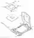
BRIEF DESCRIPTION OF THE DRAWINGSFIG. 1 is a perspective view of an LGA electrical connector according to an embodiment of the present invention, with a first cover member and an IC chip unassembled onto the LGA electrical connector;
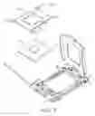
FIG. 2 is an assembled, perspective view of the LGA electrical connector of FIG. 1, with part of the insulative housing cut off to show a recess for receiving a latching element of the first cover member; and
FIG. 3 is a perspective view of a conventional LGA electrical connector.
DETAILED DESCRIPTION OF PREFERRED EMBODIMENTReferring to FIGS. 1 to 2, an LGA connector 100 according to the embodiment of the present invention is shown to include an insulative body or housing 2 with a plurality of contacts (not shown), a stiffener 3, a first cover member 4, a second cover member 5 and a lever 6.
The insulative housing 2 is generally of a rectangular shape, and has a top surface adapted for receiving an LGA package 7. The insulative housing 2 further includes a receptacle configured for receiving a latching member of the first cover member 4. In this embodiment, the receptacle includes a pair of mounting slots 21 located at a front end of the insulative housing 2, and adapted for receiving a pair of latching elements 41 of the first cover member 4.
The stiffener 3 is generally made of metallic material, and defines an opening for grasping a periphery edge of the insualtive housing 2. The stiffener 3 further includes respective receptacles 31, 33 at two opposite ends of the stiffener 3 for receiving the lever 6 and the second cover member 5 so as to enable the lever 6 and the second cover member 5 to be attached thereto.
The first cover member 4 is generally made of metallic material. The first cover member 4 includes four concave-convex side rails 42 extending from the first cover member 4 toward the top surface of the insulative housing 3 to form an opening 45 therebetween for receiving at least part of the LGA package 7, with free end edges 420 of the side rails 42 bearing against the LGA package 7, to be retained on the insulative housing 3. The first cover member 4 includes a latching member 41 adapted for being attached to a front end of the insulative housing 2. In this embodiment, the latching member 41 includes a pair of latching elements 410 located at opposite sides of the front end of the first cover member 4. Each of the latching elements 410 is preferably in a form of mounting ear, for being received in the mounting slots 21 of the insulative housing 2 so as to have the first cover member 4 be attached to the insulative housing 2 and be rotated about the front end of the insulative housing 2. In addition, the first cover member 4 includes another pair of latching catches 43 located at a rear end of the first cover member 4, and adapted for grasping a part of the insulative housing 2 around a rear end of the insulative housing 2. The catches 43 of the first cover member 4 are structurally different from that of the mounting ears 410 of the first cover member 4.
The second cover member 5 has portions for being received in the receptacles 31 of the stiffener 3 adjacent the rear end of the stiffener 3 so as to be pivotally attached to the rear end of the stiffener 3, and capable of being rotated upon the first cover member 4. The lever 6 has at least a part for being received in another receptacle 31 of the stiffener 3 adjacent the front end of the stiffener 3 so as to be pivotally attached to the front end of the stiffener 3. The lever 6 is adapted for locking the second cover member 5 in a closed position at a free end of the second cover member 5 opposite to the rear attached end of the second cover member 5 so as to cooperate with the first cover member 4 and the second cover member 5 to hold the LGA package 7 on the insulative housing 2.
Referring to FIGS. 1 and 2, in assembly, the insulative housing 2, the stiffener 3, the lever 6 and the second cover member 5 are pre-assembled in a known manner. The LGA package 3 is then placed onto the top surface of the insulative housing 2. The first cover member 4 is attached to the front end of the insulative housing 2 by the mounting ears 41 of the first cover member 4 received in the corresponding mounting slots 21 of the insulative housing 2 to enable the first cover member 41 rotate about the front end of the insulative housing 2.
Referring particularly to FIG. 2, in use, the first cover member 4 is pivotably attached to the front end of the insulative housing 2 so as to be rotated towards the top surface of the LGA package 7 with free end edges 420 of the side rails 42 bearing against the top surface of the LGA package 7, and catches 43 at the rear end of the first cover member 4 for grasping the portions around the rear end of the insulative housing 2. The second cover member 5 is pivotably attached to the rear end of the stiffener 3 opposite to the front end of the insulative housing 2 to be rotated upon the first cover member 4. The lever 6 is pivotably attached to the front end of the stiffener 3 for locking the second cover member 5 at its free end of the second cover member 5 so as to cooperate with the first cover member 4 and the second cover member 5 to hold the LGA package 7 on the insulative housing 2. Since the first cover member 4 is fixably attached to one side of the LGA connector 100, such as to a front end of the insulative housing 2, and the second cover member 5 is attached to an opposite side of the LGA connector 100, such as to the rear end of the stiffener 3, force from the opposite sides of the LGA connector 100 due to the attachments of the first cover member 4 and the second cover member 5 to the LGA connector 100, is evenly exerted on the top surface of the LGA package 7. As compared with the prior art, with such an even force exerted on the LGA package 7 of the LGA connector 100, the whole LGA package 7 will be disposed in a parallel relationship with respect to the top surface of the insulative housing 2. Thus, a reliable electrical connection between the LGA package 7 and the LGA connector 100 will be achieved.
While the first cover member 4 attached to the front end of the insulative housing 2 is preferred according to this embodiment, the first cover member 4 attached to any portion of the LGA connector 100 opposite to the attachment position of the second cover member 5 can be also employed. For example, in an alternative embodiment of the present invention, the first cover member 4 is attached to the front end of the stiffener 3 but not to the insulative housing 2 as shown in this embodiment.
While the present invention has been described with reference to preferred embodiments, the description of the invention is illustrative and is not to be construed as limiting the invention. Various of modifications to the present invention can be made to preferred embodiments by those skilled in the art without departing from the true spirit and scope of the invention as defined by the appended claims.
Claims
What is claimed is:1. A land grid array (LGA) electrical connector comprising:
an insulative housing having a plurality of contacts, the insulative housing having a top surface for receiving an LGA package;
a stiffener defining an opening for grasping a peripheral edge of the insulative housing;
a first cover member pivotally attached to a front end of one of the insulative housing and the stiffener, the first cover member adapted to be rotated towards the top surface of the insulative housing and for engaging with the LGA package on the insulative housing;
a second cover member pivotally attached to a rear end of the stiffener opposite to the attached end of said first cover member and rotatable to rest upon the first cover member; and
a lever pivotally attached to an opposite front end of the stiffener, the lever adapted for locking a free end of the second cover member opposite to the attached end of the second cover member so as to cooperate with the cover members to hold the LGA package on the insulative housing.
2. The LGA electrical connector as recited in claim 1, wherein said first cover member includes a latching member attached to the front end of the insulative housing.
3. The LGA electrical connector as recited in claim 2, wherein said latching member includes a pair of latching elements formed on opposite sides of said attached end of the first cover member.
4. The LGA electrical connector as recited in claim 3, wherein each of the latching elements is formed as an ear.
5. The LGA electrical connector as recited in claim 2, wherein the insulative housing defines a recess for receiving the latching member.
6. An LGA (Land Grid Array) socket assembly comprising:
an insulative housing;
a plurality of contacts disposed in the housing;
a metallic stiffener surrounding the housing;
a first cover pivotally mounted to one end of the stiffener;
a lever pivotally mounted to the other end of the stiffener; and
a second cover associated with the stiffener with at least one end engaged with the stiffener; wherein
the first cover abuts downwardly against and applies forces upon the second cover.
7. An LGA (Land Grid Array) socket assembly comprising:
an insulative housing;
an electronic package seated upon the housing;
a plurality of contacts disposed in the housing;
a metallic stiffener surrounding the housing;
a first cover pivotally mounted to one end of the stiffener;
a lever pivotally mounted to the other end of the stiffener; and
a second cover seated upon the electronic package while having at least one portion also engaged with the stiffener; wherein
the first cover abuts downwardly against and applies forces upon the second cover, and the second cover applies the forces to the electronic package and the stiffener.
Images & Drawings included:


Sources:
- United States Patent and Trademark Office - verify current appl. status at the USPTO↗
Recent applications in this class:
- » 20210378121 2021-12-02
Connector, IC package, and method of mounting contacts to housing of connector - » 20210068287 2021-03-04
ELECTRIC CONNECTION BOX - » 20190387638 2019-12-19
High frequency BGA connector - » 20180317335 2018-11-01
High frequency BGA connector - » 20150163944 2015-06-11
Plug standards-compliant circuit modules and connectors - » 20140099827 2014-04-10
Electrical connector with carrier frame loading electronic package - » 20130342980 2013-12-26
Surface mount device - » 20130149886 2013-06-13
Electrical connector incorporated with pick-and-place pick-up cap - » 20130082206 2013-04-04
LIQUID CRYSTAL POLYESTER COMPOSITION - » 20120302082 2012-11-29
Socket connector having a housing with a latching block and a retention plate with a latching arm
Recent applications for this Assignee:
- » 20110045702 2011-02-24
Electrical cable connector assembly with improved wire organizer - » 20110021088 2011-01-27
Electrical connector with improved contact footprints - » 20110021082 2011-01-27
High density backplane connector having improved terminal arrangement - » 20110008982 2011-01-13
N-in-1 card connector - » 20110005825 2011-01-13
Cable assembly with EMI protection - » 20110003508 2011-01-06
Electrical connector rotatably mounted to a portable device - » 20100330822 2010-12-30
Electrical connector having contact with upper terminal and lower terminal - » 20100317218 2010-12-16
Electrical connector assembly with latching mechanism - » 20100297861 2010-11-25
Socket connector having improved actuating mechanism for driving moving plate - » 20100291799 2010-11-18
Shielded connector with enlarged base supporting cantilevered brackets extending from the shielded connector