Trolling motor steering positioner
US20070197109A1
2007-08-23
11/307,694
2006-02-17
✅ Patent granted
US 7,455,558 B2
2008-11-25
-
-
Lars A Olson | Daniel V Venne
2026-02-17
Abstract:
Trolling Motor Steering Positioner: A trolling motor steering positioner (1) mounted on electric trolling motor shaft blocks (20) used on boats. The positioner (1) is made up of a tiller (12), which has a positioning pin attached to it and is attached to a circular disc (2) with holes (3) in it. The tiller (12) once located at any position on the circular disc (2) can then steer the trolling motor.
Inventors:
- Benny Wayne Yander 1 🇺🇸 Prairieville, LA, United States
- Benny Yander 1 🇺🇸 Prairieville, LA, United States
Interested in similar patents?
Get notified when new applications in this technology area are published.
Classification:
B63H5/20 IPC
Arrangements on vessels of propulsion elements directly acting on water of propellers of emergency propellers, e.g. arranged at the side of the vessel movable from a working position to a non-working position
B63H5/125 IPC
Arrangements on vessels of propulsion elements directly acting on water of propellers movably mounted with respect to hull, e.g. adjustable in direction, e.g. podded azimuthing thrusters
B63H20/007 » CPC main
Outboard propulsion units, e.g. outboard motors or Z-drives; Arrangements thereof on vessels Trolling propulsion units
B63H25/48 » CPC further
Steering; Slowing-down otherwise than by use of propulsive elements ; Dynamic anchoring, i.e. positioning vessels by means of main or auxiliary propulsive elements Steering or slowing-down by deflection of propeller slipstream otherwise than by rudder
B63H20/08 IPC
Outboard propulsion units, e.g. outboard motors or Z-drives; Arrangements thereof on vessels Means enabling movement of the position of the propulsion element, e.g. for trim, tilt or steering; Control of trim or tilt
Description
BACKGROUND1. Field of Invention
This invention relates to improving the steering mechanism for electric trolling motors used on boats.
2. Discussion of Prior Art
Electric trolling motors are used to position a fishing boat when a small quiet motor is desired over a boat's primary propulsion system. These trolling motors are usually operated while a game fisher is casting with a rod and reel. Power is applied utilizing either the controller on the trolling motor handle, which is provided by the factory, or by pre-setting this controller and using a foot button switch to start and stop the motor as desired by the operator, enabling both hands to be free to cast and net the fish once caught. When the trolling motor is switched on, the propeller provides considerable thrust, which causes side loading of the single bushing on which the motor shaft allows the steering angle to rotate. Because the motor and propeller are located under the waterline, a long shaft is incorporated to provide a watertight conduit for power and allow for steering. Because of the high bushing load, it is difficult to make steering changes using prior art while the motor is running. This forces the operator to shut off the motor, adjust the steering angle, and turn the motor on with a foot switch, repeatedly. This is an awkward and inefficient process. Use of the trolling motor steering positioner is novel over prior art in that its main purpose is to provide greater leverage so that the operator can change the direction of the trolling motor while the motor is running and the propeller is turning, and that any angle of the tiller is adjustable at any thrust level from any of 360 degrees in position. This type of product has never been observed in the marketplace.
Objects and Advantages
Accordingly, it is an object of this invention to introduce several objects and advantages.
-
- (1) The steering positioner is constructed of a circular disc with indexing holes and an engagement pin that provide adjustments of the tiller 360 degrees.
- (2) The movement from one hole to any other can be done with one hand without tools and the operator can move the tiller position to match his or her position in the boat while keeping the original position of the motor stationary.
- (3) The force is applied to the shaft at the centerline making the turning force equal regardless of an operator's position.
- (4) The steering positioner can be attached to most existing manual controlled trolling motors without the need to disassemble any of the manufacturers parts.
- (5) The steering positioner provides a higher mechanical advantage by incorporating a longer tiller.
Still further objects and advantages will become apparent from a consideration of the ensuing description and drawings. No other devices that attempt to alleviate the inconveniences described in Prior Art accomplish the objective to keep a trolling motor running while making small incremental adjustments from multiple locations in the boat.
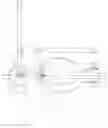
DRAWING FIGURESThe drawings show various aspects of the trolling motor steering positioner including the tiller positioner assembly and the mounting bracket assembly.
FIG. 1A Tiller positioner assembly
FIG. 1B Mounting bracket assembly
REFERENCE NUMERALS IN DRAWINGS
- (1) Trolling motor steering positioner
- (2) Circular disc
- (3) Indexing holes
- (4) Mounting bracket
- (5) Hole
- (6) Low resistance washer
- (7) C-channel bracket
- (8) Hole
- (9) Allen bolt
- (10) Nut
- (11) Washer
- (12) Tiller
- (13) Bolt
- (14) Nut
- (15) Washer
- (16) Swivel knob
- (17) Adjustable handle
- (18) Alignment pin
- (19) Hole(s)
- (20) Trolling motor shaft block
- (21) Bolt(s)
- (22) Nut(s)
- (23) Washer(s)
- (24) Hole(s)
- (25) Trolling motor housing
- (26) Trolling motor shaft
Description FIGS. 1A-1B
FIGS. 1A-1B show a typical embodiment of the trolling motor steering positioner 1. FIG. 1 A shows a top view of the trolling motor steering positioner 1. A circular disc 2 with indexing holes 3 drilled into it is welded on to the mounting bracket 4. A hole 5 is drilled into the middle of the circular disc 2. A low resistance washer 6 is placed between the circular disc 2 and a c-channel bracket 7, which has a hole 8 drilled through it. FIG. 1B shows how the c-channel bracket 7 is held in place by an alien bolt 9, nut 10, and washer 11. FIG. 1A also shows how the tiller 12 is placed into the c-channel bracket 7 and is held in place by bolt 13, nut 14 and washer 15. Also shown in FIG. 1A is how the tiller 12 can be folded with a swivel knob 16 and the length could be adjusted via an adjustable handle 17 (shown in FIG. 1B).
FIG. 1B is a rear view of the trolling motor steering positioner 1 with the tiller 12 positioned at a 90-degree angle to the right. An alignment pin 18 is shown, which is welded or fastened to the under side of the tiller 12. One can also see that the c-channel bracket 7 has holes 19 drilled into it through which bolt 13, nut 14, and washer 15 are placed. The mounting bracket 4 is attached to the trolling motor shaft block 20 with bolts 21 nuts 22 and washers 23 through holes 24. Also shown in FIG. 1B is how the mounting bracket 4 surrounds the trolling motor housing 25 and the trolling motor shaft 26.
Operation FIGS. 1A-1B
The manner of using the trolling motor steering positioner to steer a boat while under power of the trolling motor is much simpler and effective than current methods where the operator may need to turn off the trolling motor, adjust direction and then restart the motor. The operator turns on the trolling motor and uses the tiller to steer the boat in the desired direction. When the operator needs to move to another position in the boat, he or she simply lifts the tiller and moves it to the desired location, dropping the alignment pin in a new hole. From that position, the operator can then begin steering in any direction.
Conclusions, Ramifications and ScopeAccordingly, the reader will see that the trolling motor steering positioner of this invention can be used to steer a boat with great ease while the trolling motor is running. Although the description above contains many specificities, these should not be construed as limiting the design, colors or shapes of the invention but as merely providing illustrations of some of the presently preferred embodiments of this invention. For example, the bracket may have other shapes such as oval or square, etc. Thus the scope of the invention should be determined by the appended claims and their legal equivalents, rather than by the examples given above.
Claims
What is claimed is:1. A steering positioner in combination with a boat trolling motor comprising,
the steering positioner including a tiller with a positioning pin attached to it and mounted to a circular plate, which rotate freely in all directions to locate the positioning pin into holes located in the circular plate,
the steering positioner attached to a bracket mounted onto a boat trolling motor shaft block,
Request for Constructive Assistance
Applicant has written the specification and claims of this application to the best of his knowledge so that they are proper, definite, and define novel structure, which is also unobvious. If, for any reason this application is not believed to be in full condition for allowance, applicant respectfully requests the constructive assistance of the Examiner pursuant to M.P.E.P § 706.03(d) and § 707.07(j) to write a proper claim in order that this application be in allowable condition as soon as possible and without the need for further proceedings.
Images & Drawings included:

Sources:
- United States Patent and Trademark Office - verify current appl. status at the USPTO↗
Recent applications in this class:
- » 20250289548 2025-09-18
DEVICE FOR STEERING A TROLLING MOTOR AND METHOD OF THE SAME - » 20250276776 2025-09-04
WO brakes - » 20250206426 2025-06-26
A MARINE PROPULSION UNIT COMPRISING A COMPOUND PLANETARY GEAR - » 20250178709 2025-06-05
PLASMA PROCESSING APPARATUS - » 20240300632 2024-09-12
TROLLING MOTOR FUSE - » 20230382508 2023-11-30
ALTERNATING CURRENT BOAT PROPULSION SYSTEM - » 20230303227 2023-09-28
Marine vessel propulsion apparatus - » 20230192258 2023-06-22
DEVICE FOR STEERING A TROLLING MOTOR AND METHOD OF THE SAME - » 20230150633 2023-05-18
ELECTRIC OUTBOARD MOTOR - » 20230102255 2023-03-30
Combined trim and steering trolling motor system