Multi-positional smoothing mirror for video projection optics
US20070201007A1
2007-08-30
11/579,300
2005-05-10
✅ Patent granted
US 8,167,437 B2
2012-05-01
WO; PCT/US2005/016147; 20050510
WO; WO2005/114996; 20051201
Rochelle-Ann J Blackman
2025-10-18
Abstract:
A projection display is provided with a light engine including a damped piezo-electric smooth picture actuating device. The light engine comprises a mirror and an actuator for positioning the mirror. The actuator includes a tilting means that couples the actuator to the mirror. The tilting means has damping material attached thereto. The damping material may be a polymeric material.
Assignee:
- THOMSON LICENSING 1,977 🇫🇷 Boulogne-Billancourt, France
Interested in similar patents?
Get notified when new applications in this technology area are published.
Classification:
G02B7/1821 » CPC further
Mountings, adjusting means, or light-tight connections, for optical elements for prisms; for mirrors for mirrors for rotating or oscillating mirrors
G02B26/0816 » CPC further
Optical devices or arrangements for the control of light using movable or deformable optical elements for controlling the direction of light by means of one or more reflecting elements
G03B21/10 » CPC further
Projectors or projection-type viewers; Accessories therefor Projectors with built-in or built-on screen
G03B21/28 » CPC further
Projectors or projection-type viewers; Accessories therefor; Details Reflectors in projection beam
H04N9/3141 » CPC further
Details of colour television systems; Picture reproducers; Projection devices for colour picture display, e.g. using electronic spatial light modulators [ESLM] Constructional details thereof
G03B2205/0061 » CPC further
Adjustment of optical system relative to image or object surface other than for focusing; Driving means for the movement of one or more optical element using piezoelectric actuators
G03B21/14 » CPC main
Projectors or projection-type viewers; Accessories therefor Details
H04N5/74 IPC
Details of television systems Projection arrangements for image reproduction, e.g. using eidophor
G02B7/182 IPC
Mountings, adjusting means, or light-tight connections, for optical elements for prisms; for mirrors for mirrors
Description
CROSS-REFERENCE TO RELATED APPLICATIONSThis application claims the benefit of U. S. Provisional Patent Application Ser. No. 60/570,595, entitled “Multi-Positional Smoothing Mirror for Video Projection Optics” and filed May 13, 2004, which is incorporated by reference herein in its entirety.
FIELD OF THE INVENTIONThe invention relates generally to a projection display and, in particular a smoothing mirror for a projection display.
BACKGROUND OF THE INVENTIONSome new projection televisions include a light engine. Such light engines use a piezo-electric actuator and a rocking mechanism to hit a smoothing mirror between two locations. One example of the smooth picture actuator is a spring-mass type system. The piezo-electric actuator is designed to multiplex a video image that is decomposed into two sub-images. When sub-image A is projected on the screen, a small mirror ˜25 mm×25 mm is held in position “A”. Microseconds later, when sub-image B is projected, the piezo-electric motor is actuated and moves the rocker arm that the mirror is attached to into position “B”. When the next sub-image “A” is projected, current is removed form the piezo device and a return spring, for example, moves the mirror and rocker arm back into position “A”.
In the presence of audible noise from speakers or shock waves that can be transmitted by someone walking across a floor, there can be transmission of these forces into the light engine and into the piezo-electric actuator device. It is not uncommon for the amplitude of these forces to be amplified as they are transmitted through the system of the television cabinet plastics and light engine. When these forces are transmitted to the piezo-electric actuator device they may be large enough to undesirably induce motion in the rocker arm that overcomes the spring force and allows the mirror to oscillate outside of its intended frequency
SUMMARY OF THE INVENTIONAccording to an exemplary embodiment of the invention, a projection display is provided with a light engine including a damped piezo-electric smooth picture actuating device. The light engine comprises a mirror and an actuator for positioning the mirror. The actuator includes a tilting means that couples the actuator to the mirror. The tilting means has damping material attached thereto. The damping material may be a polymeric material.
BRIEF DESCRIPTION OF THE DRAWING FIGURESThe preferred embodiments of the present invention will be described with reference to the accompanying drawing figures, of which:
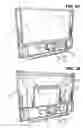
FIGS. 1A and 1B are perspective front views of a projection display according to an exemplary embodiment of the present invention, with FIG. 1A shown with a front panel removed to show a light engine of the projection display and FIG. 1B shown with a screen removed to show a light box;
FIG. 2 is a detail perspective front view of the projection display of FIGS. 1A and 1B, shown with the front panel in place;
FIG. 3 is a detailed perspective front view of the projection display of FIGS. 1A, 1B, and 2, shown with the front panel removed;
FIG. 4 is an exploded front view of the projection display of FIGS. 1A, 1B, 2, and 3;
FIG. 5 is a detailed front view of a light engine of a projection display according to an exemplary embodiment of the present invention;
FIG. 6 is a detailed view of a damped actuator device of the present invention used in the light engine of FIGS. 1A, 1B, 2, 3, 4, and 5; and
FIGS. 7A-7C each depicts a front view of damped tilting means of the present invention.
DETAILED DESCRIPTIONAccording to an exemplary embodiment of the invention, a projection display, is provided with a light engine including a damped piezo-electric smooth picture actuating device. As shown in FIGS. 1A-5, the projection display comprises a cabinet 10 that is formed from a molded plastic and comprises an electronic area 30, a mirror 22 and a light box 20. A light engine 40 comprises an output end 40a from which a light pattern is projected and an electronic end 40b having a lamp and various electronic components therein. The light engine 40 is mounted with the output end 40a in the light box 20 of the cabinet 10 and with the electronic end 40b in the electronic area 30. As shown in FIG. 1A a screen 12 is mounted over the light box 20
A removable front cover 14 (shown in FIG. 2) covers the light engine 40 and the electronic area 30, when it is installed on the cabinet 10.
According to an exemplary embodiment of the invention, a light engine comprises a mirror and an actuator. The actuator includes a frame 100 (FIG. 6) within which is located a tilting means 105 for positioning the mirror (not shown). The actuator includes a tilting means that couples the actuator to the mirror. The tilting means 105 has damping material 110 (FIGS. 7A-7C) attached thereto. The damping material may be a polymeric material.
In one embodiment shown in FIG. 7A, a round piece of shock damping material 110 is inserted into a circular opening in a coil or compression type spring. 120 (tilting means) of the piezo-electric actuator. The shock damping material 110 may for example, be slightly larger in outer diameter than the inner diameter of the spring 120 to ensure positive contact is made around the perimeter of the shock damping material 110. The addition of the shock damping material 110 to the spring 120 eliminates the natural vibratory resonance that is inherent to coil, or compression springs.
In another embodiment shown in FIG. 7B, the shock damping material 130 is overmolded to the center portion of the compression spring 135. In this embodiment, a spring may be placed in an injection mold and allow damping material to be molded into the center of the spring as well as encompassing the outside of the coils as well. This process may be applied over a portion of the middle of the spring in an area for example, approximating 3 mm.
Another embodiment shown in FIG. 7C, may include the shock damping material 140 attached on the two ends 145, 146 of the spring 143. This arrangement allows the center of the spring to be free floating and would dampen the coil spring directly at its interface with the mating parts of the actuator.
Tests were performed on springs with and without shock damping material as shown in FIGS. 7A-7C. Prior to shock material installation, the small mirror exhibited unwanted vibratory oscillation at 100 Hz, 140 Hz, 200 Hz and 420 Hz when an audible sine sweep was applied to front speakers of the projection television. After the shock damping material was added to the tilting means, for example, the spring, the presence of the unwanted oscillation disappeared.
The foregoing illustrates some of the possibilities for practicing the invention. Many other embodiments are possible within the scope and spirit of the invention. It is intended, therefore, that the foregoing description be regarded as illustrative rather than limiting, and that the scope of the invention be given by the appended claims together with their full range of equivalents.
Claims
1. A light engine for a projection system, comprising:
a mirror; and
an actuator for positioning the mirror, wherein a tilting means having damping material attached thereto couples the actuator to the mirror.
2. The light engine of claim 1 wherein the tilting means is one of a coil and a spring.
3. The light engine of claim 1 wherein the damping material is a polymeric material.
4. The light engine of claim 1 wherein the damping material has a larger diameter than that of the tilting means.
5. The light engine of claim 1 wherein the damping material is attached to the center of the tilting means.
6. The light engine of claim 1 wherein the damping material is attached to at least two portions of the damping means.
7. The light engine of claim 6 wherein the damping material is attached to two ends of the tilting means.
8. A projection system, comprising:
a light engine with a mirror; and
an actuator for positioning the mirror, wherein a tilting means having damping material attached thereto couples the actuator to the mirror.
9. The projection system of claim 8 wherein the tilting means is one of a coil and a spring.
10. The projection system of claim 8 wherein the damping material is a polymeric material.
11. The projection system of claim 8 wherein the damping material has a larger diameter than that of the tilting means.
12. The projection system of claim 8 wherein the damping material is attached to the center of the tilting means.
13. The projection system of claim 8 wherein the damping material is attached to at least two portions of the damping means.
14. The projection system of claim 13 wherein the damping material is attached to two ends of the tilting means.
Images & Drawings included:


Sources:
- United States Patent and Trademark Office - verify current appl. status at the USPTO↗
Recent applications in this class:
- » 20250208493 2025-06-26
OPTICAL MODULE AND PROJECTOR - » 20240419058 2024-12-19
PROJECTION SYSTEM, INSTALLATION UNIT, AND SUPPORT APPARATUS - » 20240231201 2024-07-11
PROJECTED AV DATA, HUD AND VIRTUAL AVATAR ON VEHICLE INTERIOR - » 20240176218 2024-05-30
ELECTRONIC DEVICE AND CONTROL METHOD THEREOF - » 20240134255 2024-04-25
PROJECTED AV DATA, HUD AND VIRTUAL AVATAR ON VEHICLE INTERIOR - » 20240118598 2024-04-11
System and method for image projection mapping - » 20240061323 2024-02-22
IMAGE PROJECTING SYSTEMS AND METHODS - » 20230393453 2023-12-07
PROJECTING WITH EXPANDED FIELD OF ILLUMINATION - » 20230028468 2023-01-26
VEHICLE SIDE AND REAR EXTERIOR ILLUMINATION AND PROJECTION - » 20220397812 2022-12-15
Projection lens module and projector
Recent applications for this Assignee:
- » 20170223398 2017-08-03
Management methods of a video device and corresponding video device - » 20160029335 2016-01-28
Method for reception in a wireless network and corresponding device for reception - » 20150271539 2015-09-24
Management methods of a video device and corresponding video device - » 20150254001 2015-09-10
System and method of reading data from a non-volatile storage medium through the use of a catalog - » 20150205461 2015-07-23
Method and device for composing a menu - » 20150205460 2015-07-23
Method and device for composing a menu - » 20150065158 2015-03-05
Method and system for performing service admission control - » 20140380166 2014-12-25
Method and device for composing a menu - » 20140380165 2014-12-25
Method and device for composing a menu - » 20140362025 2014-12-11
Spherical remote control