Blade for an impeller wheel
US20090035147A1
2009-02-05
12/279,202
2007-01-23
✅ Patent granted
US 8,641,364 B2
2014-02-04
WO; PCT/AT2007/000026; 20070123
WO; WO2007/092970; 20070823
David Nhu
Andrew Wilford
2030-05-31
Abstract:
Blade for an impeller wheel which is suitable for use for an impeller wheel power station. The special design of the blade ensures relatively low swirling of the water flow behind the blade and increases the utilization of the inflowing water flow as a result.
Assignee:
- Bew Betriebs und Entwicklung von Wasserkraftanlagen GmbH 1 🇦🇹 Wien, Austria
Applicant:
Interested in similar patents?
Get notified when new applications in this technology area are published.
Classification:
F04D29/245 » CPC main
Details, component parts, or accessories; Rotors specially for centrifugal pumps; Vanes; Geometry, shape for special effects
F03B17/063 » CPC further
Other machines or engines using liquid flow , e.g. of swinging-flap type with rotation axis substantially at right angle to flow direction the flow engaging parts having no movement relative to the rotor during its rotation
F05B2240/244 » CPC further
Components; Rotors for turbines of the cross-flow, e.g. Banki, Ossberger type
Y02E10/20 » CPC further
Energy generation through renewable energy sources Hydro energy
Y02E10/20 » CPC further
Energy generation through renewable energy sources Hydro energy
Y02E10/72 » CPC further
Energy generation through renewable energy sources; Wind energy Wind turbines with rotation axis in wind direction
Y02E10/72 » CPC further
Energy generation through renewable energy sources; Wind energy Wind turbines with rotation axis in wind direction
F01D5/14 IPC
Blades; Blade-carrying members ; Heating, heat-insulating, cooling or antivibration means on the blades or the members; Blades Form or construction
F01D1/06 IPC
Non-positive-displacement machines or engines, e.g. steam turbines with stationary working-fluid guiding means and bladed or like rotor, e.g. multi-bladed impulse steam turbines traversed by the working-fluid substantially radially
F01D5/04 IPC
Blades; Blade-carrying members ; Heating, heat-insulating, cooling or antivibration means on the blades or the members; Blade-carrying members, e.g. rotors for radial-flow machines or engines
F04D1/08 IPC
Radial-flow pumps, e.g. centrifugal pumps; Helico-centrifugal pumps; Multi-stage pumps the stages being situated concentrically
Description
The invention relates to a blade for an impeller wheel according to the generic term of claim 1.
One-piece, continuous blades for impeller wheels are known according to prior art. The closed configuration of these known blades causes troublesome turbulence on their back sides.
One aim of the invention is therefore to create a blade for an impeller wheel that achieves an improvement of turbulence on the back sides of the blades.
This aim is solved according to the invention by means of a blade of the type described above, in that the blade comprises at least two elements.
In a preferred embodiment of the invention the elements are separated by intermediate spaces, and/or are arranged like slats.
Another advantage of the invention is that the elements are offset from one another.
In a preferred embodiment the elements have a bend in the incoming flow direction, and are elongated in the discharge flow direction. This bend may be concave or convex.
Another advantage of the invention is that the elements extend at an angle relative to each other.
It may also be advantageous that the angle of the elements become larger outward from a wheel axis.
In a preferred embodiment the spacings between the elements may be equally large.
The invention and all further advantages are explained in further detail below, based on nonlimitative embodiments illustrated in the drawings. Therein:
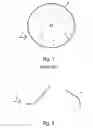
FIG. 1 is a schematic illustration of a cross-section of an impeller wheel having blades known from prior art;
FIG. 2 is a schematic cross-section of an element according to the invention;
FIG. 3 is a schematic cross-section of an impeller wheel having blades made of the elements according to the invention;
FIG. 4 is a schematic cross-section of an impeller wheel having blades made of the elements according to the invention, and a centerline;
FIG. 5 is a schematic illustration of a cross-section of an alternate impeller wheel having blades made of the elements according to the invention.
FIG. 1 represents the schematic illustration of a section across a known impeller blade 3. According to FIG. 1 an impeller wheel 3 comprises at least one blade 1 and one hub 2.
The schematic illustration in FIG. 2 shows the lateral section of an element 4 according to the invention, both in incoming flow direction, and in discharge flow direction. The incoming flow 5 of the water, and the rotational direction 6 of the impeller wheel are both illustrated. The element 5 may have a bend on its side turned toward the incoming flow of water and may be elongated toward the hub 2, or toward the interior end of the element 4 or can be straight. It has been shown to be of particular advantage, if the bend is concave or convex.
A particular embodiment of the invention is shown in FIG. 3. Multiple blades 1 configured of multiple elements 4 are attached in an impeller wheel 3. By rotating the entire blade 1 about the hub 2 of the impeller wheel 3 the position of the elements 4 relative to the flow is continuously changed. On immersion of the blade 1 (one element 4 after the other) the outermost element 4 has a position having a very low flow resistance. Upon further rotation of the blade 1 the next inner element 4 is also immersed in the flow. At a position perpendicular to the flow the elements 4 almost act like a one-piece blade 1. In other positions of the blade 1 according to the invention the water can flow through the intermediate spaces. These intermediate spaces create slat-like, or blind-like blades 1. Any troublesome turbulence on the back side of the blade 1 is reduced, and any forces counteracting movement of the impeller wheel 3 are reduced. The blade 1 made of multiple elements 4 or the centerline 7 may be either bent or straight.
As shown in FIG. 4, the impeller wheel 3 in the embodiment according to the invention, having the blades 1 configured of elements 4, may be flowed through from both directions 5. Depending on the strength of the flow, it may be necessary to align the blades 1 in an open or closed manner in the flow direction.
FIG. 5 shows a particularly effective embodiment of the present invention. The longitudinal section of a one-piece blade 1 has a centerline 7. This centerline 7 should correspond to the bend of the blade 1. At least two of the elements 4 according to the present invention are arranged on the centerline 7 such that the angle between the centerline 7 and the first element 4 is smaller than the angle between the centerline 7 and the second element 4. The intersections of the elements 4 and of the centerline 7 may have the same spacing from each other on the centerline 7. However, the spacing may also be different in a modified embodiment. In a particularly effective embodiment the elements 4 may have different sizes. The elements 4 may become smaller from the exterior toward the interior. Thus, the spacing between the elements 4 may also be different accordingly. It has been shown to be particularly effective that the spacing becomes smaller from the exterior toward the interior.
Claims
1. A blade for an impeller wheel wherein the blade comprises at least two elements.
2. The blade according to claim 1 wherein the elements are arranged such that they are separated by an intermediate space.
3. The blade according to claim 1 wherein the elements are arranged like slats.
4. The blade according to claim 1 wherein the elements are arranged in an offset manner.
5. The blade according to claim 1 wherein the elements are configured like blades.
6. The blade according to claim 1 wherein the elements extend at an acute angle relative to each other.
7. The blade according to claim 6 wherein the angle of the elements becomes larger toward a centerline from the interior toward the exterior.
8. The blade according to claim 1 wherein the elements have a bend in the incoming flow direction, and are extended in the discharge flow direction.
9. The blade according to claim 8 wherein the bend is concave or convex.
Images & Drawings included:


Sources:
- United States Patent and Trademark Office - verify current appl. status at the USPTO↗
Similar patent applications:
- » 20090309368
Water wheel impeller blade type power generator - » 20110272946
Water wheel impeller blade type electric power generating apparatus - » 20120243987
Water wheel impeller blade type electric power generating apparatus - » 20150267675
Water wheel impeller blade type electric power generating apparatus - » 20190093673
Impeller, impeller blade wheel, air-blowing device, and method of manufacturing air-blowing device - » 20210372424
Fan wheel with three dimensionally curved impeller blades
Recent applications in this class:
- » 20240318659 2024-09-26
VARIABLE INLET GUIDE VANE APPARATUS COMBINED WITH COMPRESSOR END CAP - » 20210285458 2021-09-16
Split nose blower scroll - » 20190055956 2019-02-21
Centrifugal turbo machinery - » 20140003927 2014-01-02
Blower assembly - » 20050220620 2005-10-06
Velocity profile impeller vane - » 18910266 2025-03-25
Impeller