Torque converter with lock-up clutch having a split piston
US20090133979A1
2009-05-28
12/291,611
2008-11-12
✅ Patent granted
US 8,327,987 B2
2012-12-11
-
-
Gregory Binda | Josh Skroupa
2031-05-17
Abstract:
A torque converter including a housing, a lock-up clutch, the lock-up clutch having a split piston having a radial inner portion and a radial outer portion, and a drive plate connecting the housing and the outer portion.
Assignee:
- Schaeffler Technologies AG &Co. KG 4,023 🇩🇪 Herzogenaurach, Germany
- LUK LAMELLEN UND KUPPLUNGSBAU BETEILIGUNGS KG 408 🇩🇪 Buehl, Germany
Interested in similar patents?
Get notified when new applications in this technology area are published.
Classification:
F16H2045/0231 » CPC further
Combinations of fluid gearings for conveying rotary motion with couplings or clutches with mechanical clutches for bridging a fluid gearing of the hydrokinetic type with damping means comprising two or more vibration dampers arranged in series
F16H2045/0278 » CPC further
Combinations of fluid gearings for conveying rotary motion with couplings or clutches with mechanical clutches for bridging a fluid gearing of the hydrokinetic type characterised by the type of the friction surface of the lock-up clutch comprising only two co-acting friction surfaces
Y10T29/49826 » CPC further
Metal working; Method of mechanical manufacture Assembling or joining
Y10T29/53978 » CPC further
Metal working; Means to assemble or disassemble including means to relatively position plural work parts
B25B27/14 IPC
Hand tools, specially adapted for fitting together or separating parts or objects whether or not involving some deformation, not otherwise provided for for assembling objects other than by press fit or detaching same
B23P11/00 IPC
Connecting or disconnecting metal parts or objects by metal-working techniques not otherwise provided for
F16H45/02 » CPC main
Combinations of fluid gearings for conveying rotary motion with couplings or clutches with mechanical clutches for bridging a fluid gearing of the hydrokinetic type
Description
Priority to U.S. Provisional Patent Application Ser. No. 61/003,107, filed Nov. 14, 2007, is claimed, the entire disclosure of which is hereby incorporated by reference herein.
The present invention relates generally to dual friction surface torque converters.
BACKGROUND
U.S. Pat. No. 7,011,196, hereby incorporated by reference herein, describes a bridge or lock-up clutch for a hydrodynamic torque converter.
FIG. 1 shows a cross section of a prior art torque converter 10. Torque converter 10 includes a pump shell 2 and a housing 4. Housing 4 includes a lock up clutch 6 with a piston 8. Piston 8 is attached to leaf springs 16. Leaf springs 16 are connected to a drive plate 12 via rivet 14. Drive plate 12 is welded to cover 4 at the inner diameter of drive plate 12 at location 20.
SUMMARY OF THE INVENTION
An object of the invention is to provide a more convenient method of attaching the piston to the front cover maintaining the pistons ability to move axially. The prior art requires welding for attachment to the cover, which can be more expensive and lead to contamination or distortion. If the drive plate is moved to the engine side of the piston, between the piston and the cover, this may allow an extruded rivet to be used to attach the drive plate directly to the cover, with no need for welding or an additional component to weld to. However, this arrangement requires the rivet to be stripped from inside the cover forcing the piston bore to be larger than the riveting diameter. The balancing of riveting diameter and piston bore diameter becomes increasingly difficult to adjust with increased torque requirements.
The present invention provides a torque converter including a housing; a lock-up clutch, the lock-up clutch having a split piston having a radial inner portion and a radial outer portion; and a drive plate connecting the housing and the outer portion.
BRIEF DESCRIPTION OF THE DRAWINGS
FIG. 1 illustrates a sectional view of a torque converter in the current state of the art.
Further features and advantages of the invention will become apparent from the following detailed description taken in conjunction with the accompanying drawing, in which:
FIG. 2 illustrates a sectional view of a torque converter in the present invention.
FIG. 3 illustrates the spilt piston.
DETAILED DESCRIPTION
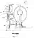
FIG. 2 shows a section of torque converter 20 which is similar in structure to the torque converter in FIG. 1 with some exceptions discussed below. Torque converter 20 includes a housing 24, a turbine 40 and a lock up clutch 42. Lock-up clutch 42 has a split piston 18 with a radial inner portion 38 and a radial outer portion 28. Radial inner portion 38 and radial outer portion 28 can be made of metal to form their ring structure.
Radial outer portion 28 of piston 18 is attached to leaf springs 26. Leaf springs 26 are connected to a drive plate 22 via rivet 44. Drive plate 22 is connected to housing 24 via a rivet 30. After drive plate 22 is riveted to housing 24, radial inner portion 38 can be assembled to outer portion 28. In addition to assembled piston 18, this creates a first chamber 46 in between assembled piston 18, drive plate 22 and housing 24. A second chamber 48 is also created in between the assembled piston 18 and turbine 40. Chambers 46 and 48 are subject to different pressures to engage or disengage lock up clutch 42. Split piston 18 is assembled to form a piston having a proper size for the apply force as determined by the piston surfaces from chambers 46 and 48. Radial inner portion 38 and radial outer portion 28 preferably have a seal 32, for example, made of rubber, between them to prevent pressure loss. Radial inner portion 38 is connected to a turbine hub 36. A seal 50, also for example, made of rubber, may be located between turbine hub 36 and radial inner portion 38.
FIG. 3 illustrates split piston 18. Radial inner portion 38 may be C shaped so that an outer radial leg 138 has an inner radial surface having a radius R2. Radial outer portion 28 may have an axially extending flange 128 having a radial outer surface of radius R1. Flange 128 and leg 138 have different radii creating a clearance between the two. The clearance between flange 128 and leg 138 allows for manufacturing tolerances and assembly. Radial inner portion 38 has an inner radial leg 139. Inner radial leg 139 contacts turbine hub 36.
The present invention allows the bore of piston 18 and the riveting location of drive plate 22 to be decoupled. It provides a cost improvement or design enhancement by reducing the number of components or reducing the damage due to welding, as well as improving ease of assembly.
Claims
What is claimed is:1. A torque converter comprising:
a housing;
a lock-up clutch, the lock-up clutch having a split piston having a radial inner portion and a radial outer portion; and
a drive plate connecting the housing and the radial outer portion.
2. The torque converter as recited in claim 1 wherein the drive plate is connected to the housing via a rivet.
3. The torque converter as recited in claim 1 further comprising a seal between the radial inner portion and the radial outer portion.
4. The torque converter as recited in claim 1 wherein the radial outer portion is connected to the drive plate with leaf springs.
5. The torque converter as recited in claim 1 wherein the drive plate is located between the radial outer portion and the housing.
6. The torque converter as recited in claim 1 wherein the radial outer portion has an axially extending flange connected to the radial inner portion with a seal.
7. The torque converter as recited in claim 6 wherein the radial inner portion is C shaped and a first outer leg of the radial inner portion has a clearance from the axial flange.
8. The torque converter as recited in claim 6 wherein the radial inner portion has a second outer leg contacting the turbine hub.
9. A method for assembling a torque converter having a lock-up clutch comprising:
attaching a radial outer portion of a piston of the lock-up clutch to a drive plate; and
attaching a radial inner portion of the piston to the radial outer portion.
Images & Drawings included:


Sources:
- United States Patent and Trademark Office - verify current appl. status at the USPTO↗
Recent applications in this class:
- » 20250290560 2025-09-18
TORQUE CONVERTER WITH PULLING BIAS SPRING - » 20250189024 2025-06-12
TORQUE CONVERTER WITH FLOATING HUB - » 20250003473 2025-01-02
Torque converter having dam and compensation reservoir - » 20240218920 2024-07-04
LOCK-UP CLUTCH HAVING RADIAL COOLING CHANNEL AND TORQUE CONVERTER USING THE SAME - » 20240151299 2024-05-09
Torque converter with turbine driven clutch connection - » 20240151298 2024-05-09
TORQUE CONVERTER WITH MULTI-PLATE CLUTCH ASSEMBLY - » 20240093769 2024-03-21
Vehicle control apparatus - » 20240052917 2024-02-15
Torque converter - » 20240011546 2024-01-11
Torque converter having floating hub - » 20240003414 2024-01-04
Torque converter
Recent applications for this Assignee:
- » 20250293624 2025-09-18
METHOD FOR DETERMINING AN INITIAL ROTOR POSITION OF A ROTOR, COMPUTER PROGRAM PRODUCT, CONTROL UNIT, ELECTRIC MACHINE, INSPECTION AND/OR TEST METHOD AND TEST STAND - » 20250290560 2025-09-18
TORQUE CONVERTER WITH PULLING BIAS SPRING - » 20250283516 2025-09-11
FREEWHEEL DEVICE AND FREEWHEEL CLUTCH - » 20250279708 2025-09-04
HYBRID DRIVE RESOLVER ROTOR MOUNTING ARRANGEMENT - » 20250273375 2025-08-28
DETENT SOLENOID - » 20250269726 2025-08-28
Electrical Circuit, On-Board Power Supply System, Vehicle, Method, Computer Program, And Computer-Readable Medium - » 20250269694 2025-08-28
ADJUSTMENT MECHANISM COMPRISING A LINEAR ACTUATOR, VEHICLE AND METHOD FOR OPERATING A VEHICLE - » 20250264157 2025-08-21
PLANETARY GEARBOX HAVING A ROTATIONALLY FIXED THRUST WASHER OF THE PLANET BEARING - » 20250263129 2025-08-21
WHEEL WELL GUARD FOR A WHEEL WELL OF A VEHICLE AND VEHICLE HAVING THE WHEEL WELL GUARD - » 20250262941 2025-08-21
Individual Monitoring Of A Plurality Of Output Points Of A System For The Vehicle-Based Supply Of External Loads