STATIC VEHICLE TIRE PUNCTURING AND DEFLATING ASSEMBLY
US20090285629A1
2009-11-19
12/520,706
2007-12-21
Abstract:
A compact vehicle tire puncturing and deflating assembly for use by law enforcement personnel in preventing high-speed chases comprising a base having a first end and a second end a spike holder attached to the first end of the base, the spike holder being permitted to rotate from a first closed position generally parallel to the base and a second tire puncturing position at an acute angle to the base; and a plurality of spikes attached to the spike holder.
Interested in similar patents?
Get notified when new applications in this technology area are published.
Classification:
F41H11/08 » CPC main
Defence installations; Defence devices Barbed-wire obstacles; Barricades; Stanchions; Tank traps; Vehicle-impeding devices; Caltrops
E01F13/12 » CPC further
Arrangements for obstructing or restricting traffic, e.g. gates, barricades ; Preventing passage of vehicles of selected category or dimensions for forcibly arresting or disabling vehicles, e.g. spiked mats
E01F15/00 IPC
Safety arrangements for slowing, redirecting or stopping errant vehicles, e.g. guard posts or bollards; Arrangements for reducing damage to roadside structures due to vehicular impact
Description
FIELD OF THE INVENTION
This invention relates generally to devices that are used by law enforcement agencies and others for intentionally puncturing the rubber tires of a motor vehicle. More particularly, this invention relates to an assembly that can be placed in front of or in back of one or more tires of a stationary vehicle for the purpose of deploying one or more spikes from the assembly in the event the vehicle is moved. It also relates to a vehicle tire puncturing and deflating spike assembly that is compact, that protects the spikes and the person carrying them during storage and otherwise, and that is quickly and easily used in the field.
BACKGROUND OF THE INVENTION
It is well known that it is occasionally necessary for law enforcement agencies to impede and stop the movement of a speeding motor vehicle. One method of accomplishing this is by the strategic placement of one or more tire-deflating mechanisms in the path, or the anticipated path, of the moving vehicle to impede and stop its movement. Such portable tire-deflating mechanisms often take the form of strips of material that can be set down on a roadway, the strips including some sort of puncturing device attached to it. One such mechanism, invented by this inventor, is formed with a “scissors-like” base having a plurality of tire-puncturing spikes, each of which is removably held within the base. That mechanism, including the detail of the tire-deflating spikes that are used with it, is disclosed in U.S. Pat. No. 6,357,961 and U.S. Pat. No. 6,312,189 issued to this inventor, respectively.
In the experience of this inventor, there is another scenario where a tire-puncturing spike and retainer assembly can be effectively used. That is where a high speed chase is prevented in the first instance by placing a tire-puncturing spike and retainer assembly in front of or in back of one or more tires of a stationary vehicle prior to the driver having an opportunity to speed away. Such use would be considered by this inventor to be a “static” situation. Static situations may include those where a law enforcement officer has temporarily stopped a vehicle for some traffic violation or other reason, where a check-point is being used while the vehicle is at rest and a check-point attendant is performing some sort of security check of the vehicle or of its driver, or where a vehicle is the subject of a law enforcement “stake-out” where it is necessary to prevent the vehicle from moving or being used as a “get-away” vehicle. There are many other applications for such a device and the list provided here is not intended to be all inclusive or limiting in any way.
Although the tire-puncturing spike and retainer assembly described in the patents referred to above could be used for such “static” applications, such use would be cumbersome and inconvenient. Additionally, where stealth is required such that a potential driver of the vehicle is unaware that an assembly of that sort has been placed about the tires of the vehicle, the assembly should assume a smaller and less conspicuous assembly to remain undetected.
SUMMARY OF THE INVENTION
The present invention provides for a unitary, molded combination base and protective case comprised of a base, the base having a hinged connection to a spike base holding a plurality of spikes at one end and at the other having a hinged connection to a cover. In a preferred embodiment, the spike base is permitted to move between two positions, a first “open” position wherein the spike base is locked into its upright position and a second “closed” position wherein the spikes and spike base are folded downwardly against the base. Similarly, in a preferred embodiment, a cover is provided, the cover being operable to fold over the spikes when the spikes and spike base are folded downwardly towards the base. When properly positioned, maintenance of the vehicle in a stationary condition will not damage or harm the vehicle tires in any way. Upon movement of the vehicle tire, in either the forward or rearward direction, will result in the vehicle tire being pierced by one or more of the tire-puncturing and deflating spikes, thereby resulting in deflation of the tire and inoperability of the vehicle.
The foregoing and other features of the tire-puncturing spike and retainer assembly constructed in accordance with this invention will be apparent from the detailed description that follows.
BRIEF DESCRIPTION OF THE DRAWINGS
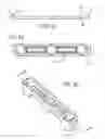
FIG. 1a is a top, plan view of a preferred embodiment of the static stop assembly and showing the assembly in the “open” position.
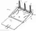
FIG. 1b is a top, left and front perspective view of the static stop assembly and showing the assembly in the “open” position.
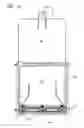
FIG. 1c is a rear elevational view of the static stop assembly and showing the assembly in the “open” position.
FIG. 1d is a side cross-sectioned view of the static stop assembly taken along Line B-B in FIG. 1a.
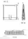
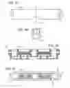
FIG. 2a is a rear elevational view of the static stop assembly and showing the assembly in the folded or “closed” position.
FIG. 2b is a top and side perspective view of the folded static stop assembly and showing the assembly in the “open” position.
FIG. 2c is a side cross-sectioned elevational view of the folded static stop taken along Line A-A of FIG. 2d.
FIG. 2d is a top plan view of the folded static stop assembly and showing the assembly in the “open” position.
FIG. 2e is a second cross-sectioned elevational view of the folded static stop.
FIG. 2f is a top plan view of the spike base.
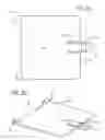
FIG. 3a is a top plan view of the cover of the assembly and showing the assembly in the “open” position.
FIG. 3b is a top and side perspective view of the cover.
FIG. 3c is a side elevational view of the cover.
FIG. 4a is a top plan view of the spike holder of the assembly and showing the assembly in the “open” position.
FIG. 4b is a rear side and front view of the spike holder.
FIG. 4c is a back elevational view of the spike holder.
FIG. 4d is a side elevational view of the spike holder.
FIG. 4e is a rear cross-sectioned elevational view of the spike holder.
FIG. 4f is a bottom plan view of the spike holder.
FIG. 5a is a rear elevational view of the base of the static stop assembly and showing the assembly in the “open” position.
FIG. 5b is a top, front and right side perspective view of the base.
FIG. 5c is a top plan view of the base.
FIG. 5d is a side elevational view of the base.
DETAILED DESCRIPTION
Referring now to the drawings in detail, wherein like numbered elements refer to like elements as well, FIG. 1 illustrates a preferred embodiment of the static tire-puncturing and deflating spike retaining assembly, generally identified 1, that is constructed in accordance with the present invention.
The static stop assembly 1 is comprised of a plurality of spikes 10, the spikes 10 being retained within a base 40 by a retaining pin 30. When in use, the spikes 10 are directed generally perpendicularly upwardly from the base 40. When stored, the spikes 10 fold under a cover 60.
In more detail, the puncturing and deflating spike 10 of the present invention includes an upwardly extending plurality of spike blades 15. Extending from the spike base 11, the spike blades 15 come together and culminate in a spike point 17. The spike point 17 serves as the initial portion of the spike 10 that contacts and pierces the tires of a motor vehicle traveling over the assembly 1. Each of the spike blades 15 of the spike 10 has a razor sharp blade edge 16 which helps slice through the rubber tire and through the steel bands contained within it as the weight of the vehicle bears upon the spike 10. Situated between each of the spike blades 15 is a longitudinally extending spike groove 18. Each spike groove 18 extends along the length of the spike 10, beginning just below the point 17 of the spike 10 and ending just above the spike base 11.
The tire spike 10 of the present invention includes a spike base void 12 (not currently shown) in the spike base 11. The spike base void 12, in actuality, extends up and into the spike 10 and terminates at a point where the spike base void 12 meets, or intersects, the spike grooves 18 which run along the exterior of the spike 10. In this fashion, the spike 10 of the present invention creates an air flow continuum which begins just below the point 17 of the spike 10, runs along the number of spike grooves 18 and terminates in a like number of openings 13 to the spike base void 12. It is this feature of the spike 10 of the present invention which aids in the tire deflating function of the spike 10, even when used to pierce today's anti-leak tires. It should also be mentioned that the placement of the spike openings 13 in the spike 10 is such that strength of the uppermost portion of the spike 10 is maximized whereby the possibility of the air flow along the spike 10 being interrupted because of a collapsed spike 10, or a portion of it, is minimized. The spikes 10 also have a pair of aligned pin apertures 19 (not currently shown) on opposite sides of the spike base void 12 and an aligning notch 14, the purpose of which will be more apparent later in this detailed description.
The base 40 has a bottom 41 having a first end 42 and a second end 43 and two identical sides 46 rising generally upwardly therefrom. The sides 46 of the base 40 are attached to the bottom 41 of the base 40 and are reinforced by a plurality of trusses 49 between the base 40 and the sides 46 of the base 40. The sides 46 of the base 40 have a small aperture 47 and a larger aperture 48, the purpose of which will become more apparent later in this detailed description.
The second end 43 of the base 40 includes a pair of gussets 45 in the bottom of the base that create a flap 51 capable of flexing slightly with respect to the bottom 41 of the base 40. The flap 51 also contains a pair of rectangular ridges 54, the purpose of which will also become more apparent later in this detailed description.
The tire puncturing device 1 further includes spike holder 20. The spike holder 20 contains a plurality of spike retaining apertures 21, each of the spike retaining apertures 21 providing an aligning slot 22 that accommodates the aligning notch 14 of the spike 10 to prevent rotation and unintended removal of the spike 10 in and from the spike aperture 21. Additionally, the alignment of the spikes 10 via the aligning notch 14 of the spike 10 and the aligning slot 22 of the spike holder 20 aligns the pin apertures 19 in the spikes 10. The spikes 10 are retained in the spike holder 20 by a retaining pin 30 that is inserted through the aperture 23 in the spike base 20 as well as the pin apertures 19 in the spikes 10.
The spike holder 20 further comprises a pair of circular knobs 24. As assembled, the circular knobs 24 are inserted through the large apertures 48 in the sides 46 of the base 40. When the retaining pin 30 is inserted through the pin aperture 23 in the spike base 20 and the pin apertures 19 in the spikes 10, the spikes 10 and the spike base 20 are permitted to rotate approximately 90 degrees about the axis created by the retaining pin 30 from a first collapsed position wherein the spikes 10 lay relatively parallel to the bottom 41 of the base 40 and are enclosed by the sides 46 of the base and a second upright position wherein the spikes 10 and spike base 20 are at an angle of approximately 90 degrees relative to the base 40.
The bottom 26 of the spike base 20 contains a cam 29, a recess 27 and a catch 28. As the spikes 10 and spike holder 20 are rotated open, the cam 29 presses the flap 51 downwardly such that the ridge 54 of the flap 51 clears the catch 28 on the spike base 20. When the spikes 10 and spike base 20 are fully in position, the ridge 54 of the flap 52 resiliently snaps into the recess 27 in the spike base 20. When the ridge 54 of the flap 51 is pressed into the recess 27 of the spike base 20, the spikes 10 are locked in their full upright position. The back 27 of the spike base 20 also includes a notch 26, the purpose of which will become more apparent later in this detailed description.
When the spikes 10 are in the collapsed position, it is advantageous to provide a cover 60. The cover 60 has a first end 61 and a second end 62, the first end 61 of the cover 60 having a plurality of hinges 67, the hinges 67 having apertures 63 therethrough. The cover 60 is attached to the base 40 via a pin 68 inserted through the small aperture 47 in the side 46 of the base 40, and through the aperture 63 in the hinges 67. It is advantageous to provide a secure means of closing the cover 10 over the spikes 60 to prevent inadvertent injury caused by contact with the spikes 10. As such, a preferred embodiment of the present invention provides for the cover 60 having a latch 65 including a catch 66, the catch 66, when closed, snapping over the notch in the spike holder 20. The latch 65 is provided some flexibility with respect to the cover 60 by gussets 64 in the cover 60.
When the cover 60 is open, the cover 60 is used to anchor the static stop device 1 under a car tire such that when the vehicle tire moves forward, it moves onto the cover 60 such that the vehicle anchors the cover 60 and base as the spike or spikes 10 pierce the tire. As such, the cover 60 should be long enough such that when it is open and the spikes 10 are in the upright position, the combined length of the cover 60 and the base 40 should be sufficient to place the second end 62 of the cover 60 under a vehicle tire such that the top 17 of the tire spike 10 is in contact with the vehicle tire.
When a vehicle tire comes into contact with the spike 10, the vehicle weight and tire resistance against penetration, and then against removal, is designed to cause the spike 10 to break away from the static stop device 1. In particular, the retaining pin 30 is engineered to be the most likely item to break, thereby releasing the spikes 10 into the tire. However, it is not essential that the spikes 10 break off the static stop 1 in order for the spikes 10 to deflate a vehicle tire.
An additional embodiment of the invention may provide for a magnet 75 attached to one or both of the sides 46 of the base 40. The person, or officer using the invention would then be equipped with a wand or other device having either an additional magnet or ferrous material at one end and a handle at the other. Such a device could be used to place the invention either in front of or behind the tire of a vehicle, without the potential distraction caused to the officer when the officer bends down.
Accordingly, it will be seen that there has been provided a new, useful and nonobvious tire-puncturing spike and retainer assembly that can be placed in front of or behind at least one tire of a stationary vehicle; that is small and relatively compact, preferably “pocket-sized” in physical dimension; that requires only a minimal number of elements of construction, that is easy to use, and that allows for less conspicuous placement in comparison to similar assemblies of current availability.
Claims
I claim:1. A static tire puncturing and deflating assembly comprising:
a base having a first end and a second end;
a spike holder attached to the first end of the base, the spike holder being permitted to rotate from a first closed position generally parallel to the base and a second tire puncturing position at an acute angle to the base; and
a plurality of spikes attached to the spike holder.
2. The static tire puncturing and deflating assembly of claim 1 wherein the spike holder further comprises a plurality of spike retaining apertures and an aperture therethrough and each of the plurality of spikes has a spike base, the spike base having an aperture therethrough, and a retaining pin that is inserted through the apertures in the spike holder to retain the spikes within the spike retaining apertures and to attach the spike holder to the base.
3. The static tire puncturing and deflating assembly of claim 2 wherein at least the first end of the base further comprises a pair of sides such that the retaining pin is further operable to secure the spike holder to the base.
4. The static tire puncturing and deflating assembly of claim 1 further comprising a cover, the cover being attached via a hinge to the second end of the base such that when the spike holder is in the first closed position generally parallel to the base the cover can be folded over the plurality of spikes and the spike holder.
5. The static tire puncturing and deflating assembly of claim 4 wherein the cover further comprises a catch mechanism that is removably securable to the spike holder.
6. The static tire puncturing and deflating assembly of claim 1 wherein the first end of the base further comprises a pair of gussets that create a flap capable of flexing slightly with respect to the base; the flap further comprising a pair of ridges, the ridges of the flap being operable to resiliently snap into a recess in the bottom of the spike holder when the spike holder is rotated to its second tire puncturing position.
7. The static tire puncturing and deflating assembly of claim 6 wherein the bottom of the spike holder comprises a cam, the cam being operable to press the rectangular ridges on the flap outwardly such that when fully open, the rectangular ridges on the flap snap into the bottom of the spike holder.
8. The static tire puncturing and deflating assembly of claim 7 wherein the spike holder is permitted to move from the second tire puncturing position to the first closed position when the flap is pressed downwardly to release the ridges in the flap from the bottom of the spike holder.
9. The static tire puncturing and deflating assembly of claim 1 wherein the base further comprises a magnet, the magnet being operable to permit the person using the tire puncturing device to employ a wand, or other reaching device with a magnet, to place the tire puncturing device without having to bend over.
10. A static tire puncturing and deflating assembly comprising:
a base having a first end and a second end, wherein the first end of the base further comprises a pair of gussets that create a flap capable of flexing slightly with respect to the base, the flap further comprising a pair of rectangular ridges;
a retaining pin;
a plurality of spikes attached to the spike holder, each of the plurality of spikes having a spike base, the spike base having an aperture therethrough; and
a spike holder having a plurality of spike retaining apertures and an aperture therethrough attached to the first end of the base, the spike holder being permitted to rotate about the retaining pin from a first closed position generally parallel to the base and a second tire puncturing position at an acute angle to the base wherein the ridges of the flap are operable to resiliently snap into a recess in the bottom of the spike holder, the retaining pin being inserted through the apertures in the spike holder to retain the spikes within the spike retaining apertures.
11. The static tire puncturing and deflating assembly of claim 10 wherein the bottom of the spike holder comprises a cam, the cam being operable to press the rectangular ridges on the flap outwardly such that when fully open, the rectangular ridges on the flap snap into the bottom of the spike holder.
12. The static tire puncturing and deflating assembly of claim 11 wherein the spike holder is permitted to move from the second tire puncturing position to the first closed position when the flap is pressed downwardly to release the ridges in the flap from the bottom of the spike holder.
13. The static tire puncturing and deflating assembly of claim 12 wherein the base further comprises a magnet and the magnet being operable to permit the person using the tire puncturing device to employ a wand, or other reaching device with a magnet, to place the tire puncturing device without having to bend over.
14. The static tire puncturing and deflating assembly of claim 10 further comprising a cover, the cover being attached via a hinge to the second end of the base such that when the spike holder is in the first closed position generally parallel to the base the cover can be folded over the plurality of spikes and the spike holder.
15. The tire puncturing device of claim 14 wherein the cover further comprises a catch mechanism that is removably securable to the spike holder.
Images & Drawings included:


Sources:
- United States Patent and Trademark Office - verify current appl. status at the USPTO↗
Recent applications in this class:
- » 20240044621 2024-02-08
Method and system for utilizing jet engines to clear drones from airspace - » 20230088686 2023-03-23
Method and system for utilizing jet engines to clear drones from airspace - » 20230027371 2023-01-26
DRIVE OFF PREVENTION DEVICE - » 20230003491 2023-01-05
Crash gate panel and components - » 20220107162 2022-04-07
Deterrent material - » 20210071997 2021-03-11
Anti-ram crash gate - » 20200393219 2020-12-17
Apparatus for hindering vehicular movement - » 20200056862 2020-02-20
Razor wire container with access opening - » 20190154407 2019-05-23
Anti-ram crash gate - » 20180245889 2018-08-30
Method and system for utilizing jet engines to clear drones from airspace