Method for the production of angiography recordings
US20100027751A1
2010-02-04
12/507,818
2009-07-23
✅ Patent granted
US 8,054,941 B2
2011-11-08
-
-
Anastasia Midkiff
2029-11-27
Abstract:
The invention relates to a method for the production of angiography recordings. First, a mask image is recorded with a first modality. A contrast medium is injected after the first recording. A control image is recorded with a second modality after the injection of the contrast medium. A spreading of the contrast medium is determined based on the images and the control of subsequent recordings is analyzed. A recording criterion is checked to determine whether the recording criterion has been achieved. If it has not been achieved, the control image is repeatedly recorded for repeatedly determining the spreading of the contrast medium. If it has been achieved, a contrast image is recorded with the first modality and the mask image and the contrast image are processed and analyzed.
Inventors:
- Jan Boese 133 🇩🇪 Eckental, Germany
- Yu Deuerling-Zheng 6 🇩🇪 Erlangen, Germany
- Michael Zellerhoff 16 🇩🇪 Forchheim, Germany
Assignee:
- SIEMENS AKTIENGESELLSCHAFT 12,417 🇩🇪 Munich, Germany
Interested in similar patents?
Get notified when new applications in this technology area are published.
Classification:
A61B6/504 » CPC main
Apparatus for radiation diagnosis, e.g. combined with radiation therapy equipment; Clinical applications involving diagnosis of blood vessels, e.g. by angiography
A61B6/4458 » CPC further
Apparatus for radiation diagnosis, e.g. combined with radiation therapy equipment; Constructional features of apparatus for radiation diagnosis related to the mounting of source units and detector units the source unit or the detector unit being attached to robotic arms
A61B6/481 » CPC further
Apparatus for radiation diagnosis, e.g. combined with radiation therapy equipment; Diagnostic techniques involving the use of contrast agents
A61B6/488 » CPC further
Apparatus for radiation diagnosis, e.g. combined with radiation therapy equipment; Diagnostic techniques involving pre-scan acquisition
A61B5/055 » CPC further
Measuring for diagnostic purposes ; Identification of persons; Detecting, measuring or recording for diagnosis by means of electric currents or magnetic fields; Measuring using microwaves or radio waves involving electronic [EMR] or nuclear [NMR] magnetic resonance, e.g. magnetic resonance imaging
A61B6/541 » CPC further
Apparatus for radiation diagnosis, e.g. combined with radiation therapy equipment; Control of apparatus or devices for radiation diagnosis involving acquisition triggered by a physiological signal
G06K9/00 IPC
Methods or arrangements for recognising patterns
H05G1/64 IPC
X-ray apparatus involving X-ray tubes; Circuits therefor; Electrical details Circuit arrangements for X-ray apparatus incorporating image intensifiers
H05G1/64 IPC
X-ray apparatus involving X-ray tubes; Circuits therefor; Electrical details Circuit arrangements for X-ray apparatus incorporating image intensifiers
H05G1/60 IPC
X-ray apparatus involving X-ray tubes; Circuits therefor; Electrical details Circuit arrangements for obtaining a series of X-ray photographs or for X-ray cinematography
H05G1/60 IPC
X-ray apparatus involving X-ray tubes; Circuits therefor; Electrical details Circuit arrangements for obtaining a series of X-ray photographs or for X-ray cinematography
H05G1/58 IPC
X-ray apparatus involving X-ray tubes; Circuits therefor; Electrical details Switching arrangements for changing-over from one mode of operation to another, e.g. from radioscopy to radiography, from radioscopy to irradiation or from one tube voltage to another
H05G1/58 IPC
X-ray apparatus involving X-ray tubes; Circuits therefor; Electrical details Switching arrangements for changing-over from one mode of operation to another, e.g. from radioscopy to radiography, from radioscopy to irradiation or from one tube voltage to another
G01N23/083 IPC
Investigating or analysing materials by the use of wave or particle radiation, e.g. X-rays or neutrons, not covered by groups – , or by transmitting the radiation through the material and measuring the absorption the radiation being X-rays
Description
CROSS REFERENCE TO RELATED APPLICATIONS
This application claims priority of German application No. 10 2008 035 549.6 filed Jul. 30, 2008, which is incorporated by reference herein in its entirety.
FIELD OF THE INVENTION
The invention relates to a method for the production of angiography recordings. The aim of angiography is to map the vascular system for diagnostic purposes. The generation of angiographic images of the vascular system generally requires two recordings of the tissue under examination: one recording without a contrast medium, a so-called mask recording, and a second recording with a contrast medium in the vessels of the region to be recorded, a so-called contrast recording.
BACKGROUND OF THE INVENTION
The recordings can be produced with the aid of various recording methods:
- Magnetic resonance tomography (MR angiography),
- Computed tomography (CT angiography),
- 3D angiography with C-arm angiography devices and/or
- X-ray projection (DSA, digital subtraction angiography).
The first three methods are cross-sectional or volume imaging methods, and the fourth method is a 2D projection method.
In addition to the imaging of vessels during angiography, the visualization of contrast medium accumulation in tissue, for example in order to measure cerebral blood volume (CBV), has an increasing role to play.
Since the contrast medium spreads out dynamically within the tissue and the vascular system, the point in time at which the second recording, the contrast recording, is made is of central importance.
Owing to the relatively small amounts of contrast medium in the tissue, an observation by a human analyzer is more difficult and the operating experience on the basis of which the timing of the contrast recordings could be set is still limited.
The second recording of an angiography, the contrast image, is usually triggered manually by the operator of the device, for example a radiologist, as described for example in U.S. Pat. No. 4,483,342, or after a delay that can be varied according to the injection, as described in U.S. Pat. No. 4,581,635. The delay is in turn set by the operator on the basis of empirical values.
DE 32 15 552 C1 describes a method for 2D projection images in which the optimal mask image, which lies shortly before the rise of the contrast medium by one pixel along the time-contrast medium curve, and the optimal contrast image, the image with the maximum contrast medium density, are determined automatically. The points in time of the two sought images are found on the time-contrast medium density curve with threshold methods.
U.S. Pat. No. 4,581,635 A describes in general terms x-ray angiography systems and digital subtraction angiography. This does not include the triggering of recordings by automatic tracking of bolus arrival at a target location, which forms the main part of our invention.
U.S. Pat. No. 5,459,769A describes a method of determining the optimal start time for the recording, but this method differs from our invention as follows:
- 1. Bolus arrival is monitored manually. We have described a fully automatic method.
- 2. Bolus arrival is determined with a time-contrast curve by means of a user-defined region of interest (ROI), whereas our method takes the whole image into consideration, thus making automatic calculation possible.
- 3. As the recording is linked to (many) user interactions, the method in D2 cannot be considered to be a triggering, which is the main idea of our invention.
SUMMARY OF THE INVENTION
The object on which the invention is based is to embody a method of the type described in the introduction such that an optimal triggering of the second recording for angiography or blood volume measurement can take place automatically.
This object is achieved according to the invention by means of a method having the following steps:
- S1 Recording of a mask image with a first modality,
- S2 Starting an injection of contrast medium,
- S3 Recording of a control image with a second modality,
- S4 Image-based determination of the spreading of the contrast medium and analysis for the control of subsequent recordings,
- S5 Determining whether a recording criterion has been achieved and, if applicable, repeating steps S3 to S5,
- S6 Recording of a contrast image with the first modality,
- S7 Processing mask image and contrast image, and
- S8 Analyzing processing step S7.
An optimal selection of recording parameters and recording methods is made possible by the automatic triggering of the second recording of an angiography or blood volume measurement on the basis of the analysis of continuously recorded control images.
According to the invention a subtraction and/or an analysis can be performed in processing step S7, the analysis in accordance with processing step S7 possibly being a blood volume measurement.
It has proven advantageous for the control images to be produced with different recording parameters, for example a lower dose, than the mask image.
Advantageously the first modality can be a modality from the following group:
- Magnetic resonance tomography (MR angiography),
- Computed tomography (CT angiography),
- 3D angiography (C-arm angiography) and/or
- X-ray projection (digital subtraction angiography (DSA)).
It is particularly advantageous if the recordings of the control images are produced using x-ray fluoroscopy.
According to the invention the analysis of processing step S7 in accordance with step S8 can be a visualization of a subtraction image.
The analysis according to step S8 of the processing of mask image and contrast image according to step S7 can advantageously be an automatic analysis of a subtraction image.
It has proven advantageous for the total amount of contrast medium in the volume being observed to be determined as the recording criterion according to step S5 for the degree of spreading of the contrast medium.
In the case of 3D imaging methods it has proven expedient for the amount of contrast medium in the volume being observed to be determined as the recording criterion according to step S5 by summation of the grayscale values across all volume elements.
In the case of projection methods, as a recording criterion according to step S5 for the degree of spreading of the contrast medium it is advantageous for the intensities of If and Im of the mask and contrast-control image to be subtracted from each other and summated across all pixels X in accordance with the following formula:
F ( t ) = ∑ x = 0 N ( ln I f ( x , t ) - ln I m ( x , t ) )
According to the invention the exceeding of a specified threshold by the volume of contrast medium can constitute the recording criterion according to step S5 for the contrast image.
Alternatively the criterion that the volume of contrast medium increases no further can be selected as the recording criterion according to step S5 for the contrast image.
The recording parameters and/or the recording method can be determined advantageously as a function of the analysis according to step S4 for controlling subsequent recordings.
BRIEF DESCRIPTION OF THE DRAWINGS
The invention is described below in more detail with reference to exemplary embodiments shown in the drawing, in which:
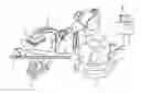
FIG. 1 shows a known x-ray C-arm system with an industrial robot as a support apparatus.
FIG. 2 shows from an axial viewing direction a view of the orbit of a detector and a radiation source according to FIG. 1 about an object to be examined,
FIG. 3 shows the flow of the method according to the invention,
FIG. 4 shows the trend in the volume of contrast medium as functions F(t) over time t, and
FIGS. 5 to 7 show different possible combinations of different recording technologies.
DETAILED DESCRIPTION OF THE INVENTION
FIG. 1 shows an x-ray diagnostic device for generating C-arm CT recordings, said device having a C-arm 2 mounted rotatably on a stand in the form of an industrial robot 1, with said C-arm having an x-ray radiation source, for example an x-ray emitter 3, and an x-ray image detector 4 arranged at its ends.
The x-ray image detector 4 can be a rectangular or square, flat semiconductor detector that is preferably made of amorphous silicon (a-Si).
A patient 6 to be examined is positioned on a patient positioning couch 5 in the path of the radiation beam of the x-ray emitter 3 for the recording of a heart for example. A system control unit 7 with an imaging system 8 is connected to the x-ray diagnostic device, said imaging system 8 receiving and processing the image signals of the x-ray image detector 4. The x-ray images can then be viewed on a monitor 9.
By means of the industrial robot 1 known for example from DE 10 2005 012 700 A1, which preferably has six axes of rotation and thus six degrees of freedom, the C-arm 2 can be displaced spatially as required, being rotated for example about a center of rotation between the x-ray emitter 3 and (including) the x-ray detector 4. The x-ray system 1 to 4 according to the invention is rotatable in particular about centers of rotation and axes of rotation at the plane of the x-ray image detector 4, preferably about the center of the x-ray image detector 4 and about axes of rotation intersecting the center of the x-ray image detector 4.
If 3D data sets are to be produced in accordance with the so-called DynaCT method known for example from the pamphlet “AXIOM Artis FD Systems/DynaCT—A Breakthrough in Interventional 3D Imaging” by Patrick Kurp, a “Reprint from Medical Solutions, January 2005, pages 46-51”, order number A91100-M1400-D105-1-7600, print reference CC 66105 SD 12043, the rotatably mounted C-arm 2 with x-ray emitter 3 and x-ray image detector 4 is rotated such that, as shown schematically in FIG. 2 by the aerial view of the axis of rotation, the x-ray emitter 3 (represented here figuratively by its beam focus) and the x-ray image detector 4 move in an orbit 10 about an object 11 to be examined. In order to produce a 3D data set the orbit 10 can be full or partial.
In accordance with the DynaCT method the C-arm 2 with x-ray emitter 3 and x-ray image detector 4 preferably moves about an angular range of at least 180°, for example 180° plus fan angle, and records projection images in rapid succession from various projections. The reconstruction can be performed using just one section of this recorded data.
The object 11 to be examined can be for example an animal body or a human body or indeed a phantom body.
The x-ray emitter 3 emits a beam of radiation 12 originating from a beam focus of its x-ray radiation source, said beam striking the x-ray image detector 4.
The x-ray emitter 3 and the x-ray image detector 4 each move about the object 5 such that the x-ray emitter 3 and the x-ray image detector 4 are positioned at opposite sides of the object 11.
In normal radiography or fluoroscopy by means of an x-ray diagnostic device of this type the medical 2D data of the x-ray image detector 4 may be buffered in the imaging system and subsequently displayed on the monitor 9.
FIG. 3 illustrates the steps involved in producing an angiography recording. In the first step S1 a mask image is recorded. These recordings can have been produced with the aid of the following recording methods, for example:
- Magnetic resonance tomography (MR angiography),
- Computed tomography (CT angiography),
- 3D angiography (C-arm angiography) and/or
- X-ray projection (digital subtraction angiography (DSA)).
The injection of contrast medium commences in the second step S2. Next a control image is recorded in the third step S3 by means of x-ray radiation. In the fourth step S4 an image-based determination of the spreading of the contrast medium is performed in this control image. In the subsequent fifth step S5 it is determined whether the recording criterion has been achieved. If this is not the case, a recording of a control image is performed in addition to that recorded in step S3, until the recording criterion is achieved. If this is the case a contrast image is recorded in the sixth step S6, which image is fed in the seventh step S7 to a subtraction function in which the mask image produced in the first step is subtracted from the contrast image. In the eighth step S8 a visualization is finally output on a display or an automatic analysis of the subtraction image is performed.
The recording criterion mentioned in FIG. 3 can be for example that the volume of contrast medium, the trend of which is shown in FIG. 4 as functions F(t) over time t, exceeds a specified threshold. This can be for example the threshold S that has been achieved at the time t1. However the recording criterion can also be fulfilled if the volume of contrast medium does not increase any further, as is the case at time t2.
By means of the method according to the invention the contrast recordings of an angiography, based on the image-based analysis of control images, can be triggered automatically.
A method of this type has the following advantages:
- Patient-specific variances in the spreading of the contrast medium are taken into consideration and consequently the number of erroneous recordings is reduced,
- Manual test injections can be avoided in particular in the case of venous injections, since a more precise and more rapid determination of the spreading of the contrast medium can be achieved than is the case by human observers, and
- Newer sensitive recording methods are made possible as a result, for example the measurement of cerebral blood volume (CBV).
The method according to the invention is conceivable in the widest possible range of combinations of recording technologies, such as those specified schematically by way of examples in the following three combinations.
FIG. 5 represents a first example of a recording technology. The mask image is produced by means of C-arm CT. The control image is monitored using fluoroscopy. The contrast image is in turn recorded by means of C-arm CT and the result is a recording in 3D angiography.
FIG. 6 shows a second example of a recording technology. A C-arm CT recording is again used as the mask image. The control is again performed by means of fluoroscopy. The contrast image is also a C-arm CT recording. However no subtraction image is produced from these images, but instead the spreading of the contrast medium is determined and a measurement of the cerebral blood volume (CBV) is performed.
FIG. 7 illustrates an example of a further recording technology. In this case an x-ray projection is used as the mask image. The control images are again produced by means of fluoroscopy. An x-ray projection is used as a contrast image, the result of which is a normal angiography recording.
The method according to the invention serves for automatically triggering the second recording of an angiography or blood volume measurement on the basis of the analysis of continuously recorded control images. Here the control images can be generated using different recording parameters (for example a lower dose) or a completely different recording method (for example x-ray fluoroscopy to record a control image for 3D angiography) than the angiography recordings themselves. The aim here is to generate the control images using a method that enables the spreading of the contrast medium to be determined within the best possible time interval and with minimal exposure for the patient (e.g. in terms of x-ray dose), and consequently to identify the ideal time for the angiography recording, which is then performed using a method that provides the best possible answers to the clinical questions.
The sequence of steps according to the invention for producing the angiography recording is as follows:
- Recording of a mask image,
- Starting the injection of contrast medium,
- Image-based determination of the spreading of the contrast medium,
- Recording of a contrast image,
- Subtraction of the mask image and contrast image, and
- Visualization or automatic analysis.
The total amount of contrast medium in the volume being observed can be determined as a criterion for the degree of spreading of the contrast medium.
In the case of 3D imaging methods the amount of contrast medium in the volume being observed can be determined by summation across all volume elements, if it is assumed that the grayscale values of a voxel have a linear relationship with the concentration of contrast medium.
On the other hand, in the case of projection methods the intensities of If and Im in the mask image and contrast image are subtracted from each other and summated across all pixels X:
F ( t ) = ∑ x = 0 N ( ln I f ( x , t ) - ln I m ( x , t ) )
The sum F then corresponds to the amount of contrast medium except for an unknown multiplicative constant. Depending on the type of imaging the constant can be determined analytically, by simulation or by calibration measurements.
The recording criterion for the contrast image can be for example that the volume of contrast medium exceeds a specified threshold (see figure, time t1) or that the volume of contrast medium increases no further (see figure, time t2).
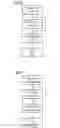
In the method according to the invention a control of subsequent recordings (in terms of parameters and recording methods) takes place as a function of the analysis. The online analysis of an “x-ray image being observed” is used to control the timing of the actual “recordings”. Not only different recording parameters but also entirely different recording methods can be used here. Provision is made in particular for the combination of 2D and 3D methods, examples of which are given in the following table.
| Online observation - | Recording - | |
| control image | mask image and contrast image | |
| 2D x-ray examination - | 3D rotation scan - | |
| fluoroscopy | C-arm CT | |
| MR angiography | MR angiography | |
| CT fluoro | CT spiral scan | |
| 2D ultrasound | 3D rotation scan | |
| 2D ultrasound | MR angiography | |
| 2D ultrasound | CT spiral scan | |
Claims
1-15. (canceled)
16. A method for a production of an angiography recording of a patient, comprising:
recording a mask image of the patient with a first imaging modality;
starting an injection of a contrast medium;
recording a control image of the patient with a second imaging modality;
determining a spreading of the contrast medium and analyzing a control of subsequent recordings based on the control image;
checking whether a recording criterion has been achieved from the spreading of the contrast medium;
repeatedly recoding the control image and determining the spreading of the contrast medium if the recording criterion has not been achieved;
recording a contrast image of the patient with the first imaging modality if the recording criterion has been achieved;
processing the mask image and the contrast image; and
analyzing the processed mask image and the processed contrast image for the production of the angiography recording of the patient.
17. The method as claimed in claim 16, wherein the processing step comprises generating a subtraction image of the mask image and the contrast image.
18. The method as claimed in claim 16, wherein the processing step comprises an analysis of the patient.
19. The method as claimed in claim 18, wherein the analysis is a blood volume measurement.
20. The method as claimed in claim 16, wherein the control image is recorded using different recording parameters than the mask image.
21. The method as claimed in claim 16, wherein the first imaging modality is selected from the group consisting of: Magnetic resonance tomography, Computed tomography, 3D angiography, and X-ray projection.
22. The method as claimed in claim 16, wherein the second imaging modality is an x-ray fluoroscopy.
23. The method as claimed in claim 16, wherein the analyzing step comprises a display of a subtraction image of the mask image and the contrast image generated in the processing step.
24. The method as claimed in claim 16, wherein the analyzing step comprises an automatic analysis of a subtraction image of the mask image and the contrast image generated in the processing step.
25. The method as claimed in claim 16, wherein the recording criterion is an amount of the contrast medium in a volume for a degree of the spreading of the contrast medium.
26. The method as claimed in claim 25, wherein for a 3D imaging method, the amount of the contrast medium in the volume is determined by summing grayscale values across all volume elements.
27. The method as claimed in claim 25, wherein for a projection method, the amount of the contrast medium in the volume is determined by subtracting an intensity If of the mask image and an intensity Im of the control image and summing across all pixels X with the following formula:
F ( t ) = ∑ x = 0 N ( ln I f ( x , t ) - ln I m ( x , t ) )
28. The method as claimed in claim 16, wherein the recording criterion is an amount of the contrast medium in a volume when exceeding a specified threshold.
29. The method as claimed in claim 16, wherein the recording criterion is an amount of the contrast medium in a volume when having no further increasing.
30. The method as claimed in claim 16, wherein the subsequent recordings are controlled by recording parameters or recording methods.
31. An image diagnostic device, comprising:
a first imaging modality that records:
a mask image of a patient before a injection of a contrast medium, and
a contrast image of the patient after the injection of the contrast medium if a recording criterion has been achieved;
a second imaging modality that records a control image of the patient after the injection of the contrast medium; and
a control unit that:
determines a spreading of the contrast medium and analyzes a control of subsequent recordings based on the control image;
checks whether the recording criterion has been achieved from the spreading of the contrast medium;
processes the mask image and the contrast image; and
analyzes the processed mask image and the processed contrast image.
Images & Drawings included:


Sources:
- United States Patent and Trademark Office - verify current appl. status at the USPTO↗
Recent applications in this class:
- » 20250288269 2025-09-18
DYNAMIC ANALYSIS APPARATUS, DYNAMIC ANALYSIS METHOD, AND STORAGE MEDIUM - » 20250213208 2025-07-03
MEDICAL SYSTEMS AND METHODS - » 20250186012 2025-06-12
METHOD AND ELECTRONIC DEVICE FOR CLASSIFYING VESSEL - » 20250169784 2025-05-29
BLOOD VESSEL IMAGE CALIBRATION METHOD AND DEVICE - » 20250160778 2025-05-22
ANALYSIS OF INTRACRANIAL BLOOD VESSELS - » 20250160777 2025-05-22
VASCULAR IMAGING METHODS, SYSTEMS, AND MEDIUMS - » 20250127473 2025-04-24
DEVICE AND METHOD TO RECONSTRUCT THREE DIMENSIONAL SHAPE OF VESSEL - » 20250127472 2025-04-24
SUSPENDED TRAVELLING EQUIPMENT AND MEDICAL IMAGING SYSTEM - » 20250120666 2025-04-17
SYSTEMS, METHODS, AND DEVICES FOR MEDICAL IMAGE ANALYSIS, DIAGNOSIS, RISK STRATIFICATION, DECISION MAKING AND/OR DISEASE TRACKING - » 20250120665 2025-04-17
SYSTEMS AND METHODS FOR CHARACTERIZING HIGH RISK PLAQUES
Recent applications for this Assignee:
- » 20250262772 2025-08-21
PLACE CONDITIONED PICK FOR ROBOTIC PICK AND PLACE OPERATIONS - » 20250242498 2025-07-31
SYSTEM AND METHOD FOR PICK POSE ESTIMATION FOR ROBOTIC PICKING WITH ARBITRARILY SIZED END EFFECTORS - » 20250216836 2025-07-03
PRIORITIZATION BETWEEN AGENTS IN AGENT-BASED PROCESS AUTOMATION - » 20250168873 2025-05-22
WLAN Communication Method and Devices - » 20250168152 2025-05-22
Communication System, Adapter for a Terminal and Method for Securely Transmitting Time-Critical Data within the Communication System - » 20250166165 2025-05-22
TRAINING SYSTEMS FOR SURFACE ANOMALY DETECTION - » 20250162095 2025-05-22
Method for Operating a Machine Tool, Computer Program Product, Control Unit, Machine Tool, Simulation Program Product and Use of the Control Unit - » 20250147755 2025-05-08
INDUSTRIAL APPLICATION PACKAGE MANAGEMENT - » 20250126041 2025-04-17
METHOD OF CAPTURING PACKETS FROM APPLICATIONS HOSTED ON CONTAINERS - » 20250117920 2025-04-10
SELF-SUPERVISED ANOMALY DETECTION FRAMEWORK FOR VISUAL QUALITY INSPECTION IN MANUFACTRUING