Vibration dampening structure for disk drive
US20100103607A1
2010-04-29
12/422,351
2009-04-13
✅ Patent granted
US 7,889,492 B2
2011-02-15
-
-
Jayprakash N Gandhi | Jerry Wu
2029-08-28
Abstract:
A vibration dampening structure for a disk drive includes a bracket for receiving the disk drive and an elastic peg for dampening vibration of the disk drive. The bracket includes a pair of side panels for receiving the disk drive therebetween. An elastic clamp is formed on each side panel. A hole is defined in the clamp. The elastic peg includes a flexible head portion abutting the disk drive, and a handle portion extending into the hole. The head portion is configured for buffering the disk drive in an inner side of the bracket. The handle portion is capable of being pulled to move the head portion and the clamp away from the disk drive for disengaging the elastic peg from the disk drive.
Inventors:
- YUN-LUNG CHEN 261 🇹🇼 Tu-Cheng, Taiwan
- PEI-BIN LUO 5 🇨🇳 Shenzhen City, China
- YUN-LUNG CHEN 68 🇹🇼 Taipei Hsien, Taiwan
- Bao Shen 2 🇨🇳 Shenzhen City, China
- PEI-BIN LUO 12 🇨🇳 Shenzhen, China
- Bao Shen 2 🇨🇳 Shenzhen, China
Assignee:
- HON HAI PRECISION INDUSTRY CO., LTD. 12,833 🇹🇼 Tu-Cheng, Taiwan
- HONG FU JIN PRECISION INDUSTRY (SHENZHEN) CO., LTD. 4,225 🇨🇳 Shenzhen City, China
- HON HAI PRECISION INDUSTRY CO., LTD. 2,357 🇹🇼 Tu-Cheng, Taipei Hsien, Taiwan
- Hong Fu Jin Precision Industry (Shenzhen) Co., Ltd. 1,915 🇨🇳 Shenzhen, Guangdong Province, China
Interested in similar patents?
Get notified when new applications in this technology area are published.
Classification:
G11B33/08 » CPC main
Constructional parts, details or accessories not provided for in the other groups of this subclass; Cabinets; Cases; Stands; Disposition of apparatus therein or thereon Insulation or absorption of undesired vibrations or sounds
G11B33/124 » CPC further
Constructional parts, details or accessories not provided for in the other groups of this subclass; Disposition of constructional parts in the apparatus, e.g. of power supply, of modules the apparatus comprising a single recording/reproducing device; Mounting arrangements of constructional parts onto a chassis of the single recording/reproducing device, e.g. disk drive, onto a chassis
G06F1/16 IPC
Details not covered by groups - and Constructional details or arrangements
H05K7/00 IPC
Constructional details common to different types of electric apparatus
H05K7/00 IPC
Constructional details common to different types of electric apparatus
H05K7/16 IPC
Constructional details common to different types of electric apparatus; Mounting supporting structure in casing or on frame or rack on hinges or pivots
H05K7/16 IPC
Constructional details common to different types of electric apparatus; Mounting supporting structure in casing or on frame or rack on hinges or pivots
H05K5/00 IPC
Casings, cabinets or drawers for electric apparatus
H05K5/00 IPC
Casings, cabinets or drawers for electric apparatus
A47B88/00 IPC
Details of furniture
A47B88/00 IPC
Drawers for tables, cabinets or like furniture; Guides for drawers
A47F7/00 IPC
Show stands, hangers, or shelves, adapted for particular articles or materials
Description
BACKGROUND
1. Technical Field
The present invention relates to vibration dampening structures and, particularly, to a vibration dampening structure for a disk drive in a computer.
2. Description of Related Art
Usually, disk drives are secured in a computer. The disk drives are conventionally secured to the computer by a plurality of screws. However, the disk drives will vibrate and produce noise when running, so it is important to stably secure the disk drives in the computer.
What is needed, therefore, is to provide a vibration dampening structure for a disk drive, having a simple structure and is easy to use.
BRIEF DESCRIPTION OF THE DRAWINGS
FIG. 1 is an isometric view of an embodiment of a vibration dampening structure for a disk drive, the vibration dampening structure including a bracket and an elastic peg.
FIG. 2 is an isometric view of the bracket of FIG. 1, but viewed from another aspect.
FIG. 3 is an isometric view of the elastic peg of FIG. 1.
FIG. 4 is an isometric view of the vibration dampening structure in the process of mounting the disk drive in the bracket.
FIG. 5 is a sectional view of the vibration dampening structure after the disk drive is mounted in the bracket.
FIG. 6 is an assembled view of the vibration dampening structure and the disk drive.
DETAILED DESCRIPTION
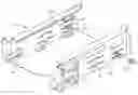
Referring to FIG. 1 and FIG. 2, an embodiment of a vibration dampening structure for a disk drive includes a bracket 10 for mounting the disk drive to dampen vibration and an elastic peg 20 for fixing the disk drive in the bracket 10 firmly.
The bracket 10 has a bottom panel 11 and substantially parallel side panels 12 extending substantially perpendicularly from two sides of the bottom panel 11. The bottom panel 11 is punched towards an inner surface of the bracket 10 to form two pairs of elastic supports 13. Each support 13 may be curved. An elastic protrusion 14 may be formed on a middle portion of each side panel 12. The protrusion 14 may be circular. Each side panel 12 is punched towards an inner side to form a clamp 15 to clamp the elastic peg 20. A pair of substantially parallel grooves 152 is defined in opposite sides of the clamp 15 to enhance an elasticity of the clamp 15. A hole 151 is defined in a middle portion of the clamp 15. A guide way 16 is formed on the side panel 12 at a front side of the side panel 12. A fixing member 17 is formed on the side panel 12 opposite to the guide way 16. The fixing member 17 has an elastic resisting portion 171 protruding from the side panel 12.
Referring also to FIG. 3, the elastic peg 20 includes a head portion 21, a neck portion 22 connecting with the head portion 21, a flange portion 23 connecting with the neck portion 22, and a handle portion 24 connecting with the flange portion 23. The head portion 21 may be convex or spherical-shaped. A width of the head portion 21 is larger than a diameter of the hole 151 of the clamp 15. A width of the neck portion 22 is substantially equal to the diameter of the hole 151.
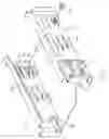
Referring to FIG. 4, a disk drive 30 is mounted in the bracket 10. A pair of recesses 31 is defined in two sides of the disk drive 30. A screw 32 extends into the recess 31. The screw 32 is inserted into the guide way 16 and pushed against the resisting portion 171. The resisting portion 171 is deformed outwardly so that the screw 32 can be slid into the guide way 16. The resisting portion 171 then returns to a normal state to prevent the disk drive 30 from sliding out. In the process of assembling the disk drive 30, the disk drive 30 is firmly fixed in the bracket 10 by the support 13 and the protrusion 14.
The elastic peg 20 is inserted into the hole 151 of the clamp 15 from the inner side of the bracket 10. The head portion 21 of the elastic peg 20 lies on the inner side of the bracket 10. The neck portion 22 is inserted in the hole 151. The flange portion 23 lies on the outer side of the bracket 10.
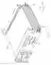
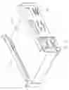
Referring to FIG. 5 and FIG. 6, when the disk drive 30 is completely mounted in the bracket 10, the head portion 21 of the elastic peg 20 engages with the recess 31 to dampen the vibration produced by the disk drive 30. The elastic peg 20 blocks the disk drive 30 and dampens vibration at an X-direction along the extension of the elastic peg 20. A Y-direction and a Z-direction substantially perpendicular to the bottom panel 11 of the bracket 10 are restricted by an engagement of the head portion 21 and the recess 31.
When disassembling the disk drive 30 from the bracket 10, the handle portion 24 of the elastic peg 20 is pulled outwards. The head portion 21 and the clamp 15 move away from the disk drive 30, thereby disengaging the disk drive 30 from the head portion 21 of the elastic peg 20.
It is to be understood, however, that even though numerous characteristics and advantages of the present invention have been set forth in the foregoing description, together with details of the structure and function of the invention, the disclosure is illustrative only, and changes may be made in detail, especially in matters of shape, size, and arrangement of parts within the principles of the invention to the full extent indicated by the broad general meaning of the terms in which the appended claims are expressed.
Claims
1. A vibration dampening structure for a disk drive, the vibration dampening structure comprising:
a bracket to receive the disk drive, the bracket comprising a pair of side panels to receive the disk drive therebetween, an elastic clamp being formed on each side panel, a hole defined in the clamp; and
an elastic peg to dampen vibration of the disk drive, the elastic peg comprising a flexible head portion abutting the disk drive, and a handle portion extending into the hole, the head portion buffering the disk drive in an inner side of the bracket, and the handle portion being capable of being pulled to move the head portion and the clamp away from the disk drive to disengage the elastic peg from the disk drive.
2. The vibration dampening structure of claim 1, wherein the head portion has a convex shape facing the disk drive.
3. The vibration dampening structure of claim 2, wherein the head portion is spherical-shaped.
4. The vibration dampening structure of claim 1, wherein a recess is defined in the disk drive to engage with the head portion.
5. The vibration dampening structure of claim 1, wherein the bracket further comprises a bottom panel; at least one curved support is formed on the bottom panel to support the disk drive.
6. The vibration dampening structure of claim 1, wherein a circular protrusion is formed on each side panel to position the disk drive in the bracket.
7. The vibration dampening structure of claim 1, wherein the elastic peg further comprises a flange portion blocking on the outer side of the side panel and a neck portion connecting the flange portion with the head portion.
8. The vibration dampening structure of claim 7, wherein a width of the neck portion is substantially equal to a diameter of the hole.
9. The vibration dampening structure of claim 1, wherein a width of the head portion is larger than a diameter of the hole.
10. The vibration dampening structure of claim 1, wherein the clamp is formed between two grooves such that a middle portion of each clamp is capable of being elastically deformed perpendicular to the side panels.
11. A vibration dampening structure for holding a disk drive, two recesses are defined in opposite sides of the disk drive, the vibration dampening structure comprising:
a bracket to receive the disk drive, the bracket comprising a bottom panel and a pair of side panels to receive the disk drive therebetween, an elastic clamp formed on each side panel; and
a flexible member to dampen vibration of the disk drive in the bracket, the flexible member being attached to the clamp, the flexible member comprising a head portion capable of executing a resilient force to the disk drive to dampen vibration at a first direction of the extension of the flexible member;
wherein when the disk drive is vibrating in the bracket, the flexible member provides resilient forces to the disk drive, the vibration is dampened by an engagement of the recess and the head portion at a third direction substantially perpendicular to the bottom panel of the bracket, and a second direction substantially perpendicular to the first direction and the second direction.
12. The vibration dampening structure of claim 11, wherein the head portion has a convex shape facing to the disk drive.
13. The vibration dampening structure of claim 12, wherein the head portion is spherical-shaped.
14. The vibration dampening structure of claim 11, wherein at least one curved support is formed on the bottom panel to buffer the disk drive.
15. The vibration dampening structure of claim 11, wherein a circular protrusion is formed on each side panel to position the disk drive in the bracket.
16. The vibration dampening structure of claim 11, wherein the flexible member further comprises a flange portion blocking on the outer side of the side panel and a neck portion connecting the flange portion with the head portion.
17. The vibration dampening structure of claim 16, wherein a width of the neck portion is substantially equal to a diameter of the hole.
18. The vibration dampening structure of claim 11, wherein a width of the head portion is larger than a diameter of the hole.
19. The vibration dampening structure of claim 11, wherein the clamp is formed between two grooves such that a middle portion of each clamp is capable of being elastically deformed perpendicular to the side panels.
Images & Drawings included:


Sources:
- United States Patent and Trademark Office - verify current appl. status at the USPTO↗
Recent applications in this class:
- » 20250087245 2025-03-13
RECORDING AND REPRODUCING DEVICE - » 20240312490 2024-09-19
DISK APPARATUS - » 20240079034 2024-03-07
RECORDING AND REPRODUCING DEVICE - » 20240079033 2024-03-07
RECORDING AND REPRODUCING DEVICE - » 20220093137 2022-03-24
Wall mounted isolating system for dampening vibration - » 20210407549 2021-12-30
Multibody chambered acoustic attenuator for a data storage system - » 20210335392 2021-10-28
Heat-dissipating, shock-absorbing structure - » 20210327473 2021-10-21
Top cover spring designs - » 20210201959 2021-07-01
Isolated vibration structure for fan bay module and HDD cage - » 20200135239 2020-04-30
Vibration isolation apparatus for server rack delivery
Recent applications for this Assignee:
- » 20140233961 2014-08-21
Optical communication module including optical-electrical signal converters and optical signal generators - » 20140083669 2014-03-27
HEAT SINK - » 20140083669 2014-03-27
HEAT SINK - » 20140063746 2014-03-06
Electronic device with heat dissipation assembly - » 20140061224 2014-03-06
AUTOMATIC VENDING MACHINE - » 20140060914 2014-03-06
Enclosure with shield apparatus - » 20140058727 2014-02-27
MULTIMEDIA RECORDING SYSTEM AND METHOD - » 20140055955 2014-02-27
Fastener - » 20140055322 2014-02-27
DISPLAY SYSTEM AND HEAD-MOUNTED DISPLAY APPARATUS - » 20140054439 2014-02-27
CONTAINER DATA CENTER WITH SUPPORTING APPARATUS