Server connectivity control for tele-presence robot
US20100131102A1
2010-05-27
12/277,922
2008-11-25
✅ Patent granted
US 9,138,891 B2
2015-09-22
-
-
Mary Cheung
Chris Lambrecht
2030-01-28
Abstract:
A robot system with a robot that has a camera and a remote control station that can connect to the robot. The connection can include a plurality of privileges. The system further includes a server that controls which privileges are provided to the remote control station. The privileges may include the ability to control the robot, joint in a multi-cast session and the reception of audio/video from the robot. The privileges can be established and edited through a manager control station. The server may contain a database that defines groups of remote control station that can be connected to groups of robots. The database can be edited to vary the stations and robots within a group. The system may also allow for connectivity between a remote control station at a user programmable time window.
Inventors:
- Yulun Wang 188 🇺🇸 Goleta, CA, United States
- Marco Pinter 121 🇺🇸 Santa Barbara, CA, United States
- Charles S. Jordan 150 🇺🇸 Santa Barbara, CA, United States
- Blair Whitney 52 🇺🇸 Santa Barbara, CA, United States
- John Cody Herzog 4 🇺🇸 Goleta, CA, United States
Assignee:
- InTouch Technologies, Inc. 106 🇺🇸 Goleta, CA, United States
Applicant:
Interested in similar patents?
Get notified when new applications in this technology area are published.
Classification:
A45C11/00 » CPC further
Receptacles for purposes not provided for in groups -
G06F1/1626 » CPC further
Details not covered by groups - and; Constructional details or arrangements for portable computers with a single-body enclosure integrating a flat display, e.g. Personal Digital Assistants [PDAs]
G06F1/1643 » CPC further
Details not covered by groups - and; Constructional details or arrangements for portable computers; Constructional details or arrangements of portable computers not specific to the type of enclosures covered by groups - ; Details related to the display arrangement, including those related to the mounting of the display in the housing the display being associated to a digitizer, e.g. laptops that can be used as penpads
G06F1/1656 » CPC further
Details not covered by groups - and; Constructional details or arrangements for portable computers; Constructional details or arrangements of portable computers not specific to the type of enclosures covered by groups - Details related to functional adaptations of the enclosure, e.g. to provide protection against EMI, shock, water, or to host detachable peripherals like a mouse or removable expansions units like PCMCIA cards, or to provide access to internal components for maintenance or to removable storage supports like CDs or DVDs, or to mechanically mount accessories
G06F1/1688 » CPC further
Details not covered by groups - and; Constructional details or arrangements for portable computers; Constructional details or arrangements of portable computers not specific to the type of enclosures covered by groups - ; Constructional details or arrangements related to integrated I/O peripherals not covered by groups - the I/O peripheral being integrated loudspeakers
H04M1/035 » CPC further
Substation equipment, e.g. for use by subscribers; Constructional features of telephone sets; Constructional features of telephone transmitters or receivers, e.g. telephone hand-sets Improving the acoustic characteristics by means of constructional features of the housing, e.g. ribs, walls, resonating chambers or cavities
H04R1/2834 » CPC further
Details of transducers, loudspeakers or microphones; Arrangements for obtaining desired frequency or directional characteristics for obtaining desired frequency characteristic only; Transducer mountings or enclosures modified by provision of mechanical or acoustic impedances, e.g. resonator, damping means; Enclosures comprising vibrating or resonating arrangements using a passive diaphragm for loudspeaker transducers
H05K5/0013 » CPC further
Casings, cabinets or drawers for electric apparatus comprising several parts forming a closed casing assembled by resilient members
H05K5/0013 » CPC further
Casings, cabinets or drawers for electric apparatus comprising several parts forming a closed casing assembled by resilient members
H05K5/0086 » CPC further
Casings, cabinets or drawers for electric apparatus portable, e.g. battery operated apparatus
H05K5/0086 » CPC further
Casings, cabinets or drawers for electric apparatus portable, e.g. battery operated apparatus
H05K5/061 » CPC further
Casings, cabinets or drawers for electric apparatus; Hermetically-sealed casings sealed by a gasket held between a removable cover and a body, e.g. O-ring, packing
H05K5/061 » CPC further
Casings, cabinets or drawers for electric apparatus; Hermetically-sealed casings sealed by a gasket held between a removable cover and a body, e.g. O-ring, packing
H05K5/069 » CPC further
Casings, cabinets or drawers for electric apparatus; Hermetically-sealed casings Other details of the casing, e.g. wall structure, passage for a connector, a cable, a shaft
H05K5/069 » CPC further
Casings, cabinets or drawers for electric apparatus; Hermetically-sealed casings Other details of the casing, e.g. wall structure, passage for a connector, a cable, a shaft
A45C2011/002 » CPC further
Receptacles for purposes not provided for in groups - for portable handheld communication devices, e.g. mobile phone, pager, beeper, PDA, smart phone
G06F2200/1633 » CPC further
Indexing scheme relating to -; Indexing scheme relating to -; Indexing scheme relating to constructional details of the computer Protecting arrangement for the entire housing of the computer
G06F2200/1634 » CPC further
Indexing scheme relating to -; Indexing scheme relating to -; Indexing scheme relating to constructional details of the computer Integrated protective display lid, e.g. for touch-sensitive display in handheld computer
H04M1/04 » CPC further
Substation equipment, e.g. for use by subscribers; Constructional features of telephone sets Supports for telephone transmitters or receivers
H04R2499/11 » CPC further
Aspects covered by or not otherwise provided for in their subgroups; General applications Transducers incorporated or for use in hand-held devices, e.g. mobile phones, PDA's, camera's
Y10S901/01 » CPC further
Robots Mobile robot
Y10S901/47 » CPC further
Robots; Sensing device Optical
G05B19/418 IPC
Programme-control systems electric Total factory control, i.e. centrally controlling a plurality of machines, e.g. direct or distributed numerical control [DNC], flexible manufacturing systems [FMS], integrated manufacturing systems [IMS], computer integrated manufacturing [CIM]
B25J19/04 IPC
Accessories fitted to manipulators, e.g. for monitoring, for viewing; Safety devices combined with or specially adapted for use in connection with manipulators; Sensing devices Viewing devices
B25J9/1689 » CPC further
Programme-controlled manipulators; Programme controls characterised by the tasks executed Teleoperation
B25J19/023 » CPC further
Accessories fitted to manipulators, e.g. for monitoring, for viewing; Safety devices combined with or specially adapted for use in connection with manipulators; Sensing devices; Optical sensing devices including video camera means
G05D1/0038 » CPC further
Control of position, course or altitude of land, water, air, or space vehicles, e.g. automatic pilot associated with a remote control arrangement by providing the operator with simple or augmented images from one or more cameras located onboard the vehicle, e.g. tele-operation
G05D1/0246 » CPC further
Control of position, course or altitude of land, water, air, or space vehicles, e.g. automatic pilot; Control of position or course in two dimensions specially adapted to land vehicles using optical position detecting means using a video camera in combination with image processing means
G05B2219/24158 » CPC further
Program-control systems; Pc systems; Pc safety Access only for service, hide, forbidden tamperfree keys, program
G05D1/0274 » CPC further
Control of position, course or altitude of land, water, air, or space vehicles, e.g. automatic pilot; Control of position or course in two dimensions specially adapted to land vehicles using internal positioning means using mapping information stored in a memory device
B25J5/00 » CPC main
Manipulators mounted on wheels or on carriages
G05D2201/0206 » CPC further
Application; Control of position of land vehicles Vehicle in a health care environment, e.g. for distribution of food or medicins in a hospital or for helping handicapped persons
G05B19/00 IPC
Programme-control systems
B25J9/16 IPC
Programme-controlled manipulators Programme controls
B25J19/02 IPC
Accessories fitted to manipulators, e.g. for monitoring, for viewing; Safety devices combined with or specially adapted for use in connection with manipulators Sensing devices
G05D1/00 IPC
Control of position, course or altitude of land, water, air, or space vehicles, e.g. automatic pilot
G05D1/02 IPC
Control of position, course or altitude of land, water, air, or space vehicles, e.g. automatic pilot Control of position or course in two dimensions
Description
BACKGROUND OF THE INVENTION
1. Field of the Invention
The subject matter disclosed generally relates to the field of robotics.
2. Background Information
Robots have been used in a variety of applications ranging from remote control of hazardous material to assisting in the performance of surgery. For example, U.S. Pat. No. 5,762,458 issued to Wang et al. discloses a system that allows a surgeon to perform minimally invasive medical procedures through the use of robotically controlled instruments. One of the robotic arms in the Wang system moves an endoscope that has a camera. The camera allows a surgeon to view a surgical area of a patient.
There has been marketed a tele-presence mobile robot introduced by InTouch Technologies, Inc., the assignee of this application, under the trademark RP-7. The InTouch robot is controlled by a user at a remote station. The remote station may be a personal computer with a joystick that allows the user to remotely control the movement of the robot. Both the robot and remote station have cameras, monitors, speakers and microphones to allow for two-way video/audio communication. The robot camera provides video images to a screen at the remote station so that the user can view the robot's surroundings and move the robot accordingly.
The InTouch robot system can be used to access any number of robots from different remote locations. For example, a hospital facility may have a number of tele-presence robots that are accessible from different remote computer stations. A physician can become connected to a robot by merely logging on through a laptop or personal computer. As the number of in-field InTouch tele-presence robots grows, it is desirable to set and edit the connectivity between various remote control stations and different robots. It is also desirable to provide a means to control the parameters of the connectivity. For example, it may be desirable to control connectivity so that multiple remote control stations can receive the audio/video provided by the robot. It may be desirable to restrict the audio and/or video provided to one or more remote control stations. It may also be desirable to establish a time window of connectivity between control stations and robots.
BRIEF SUMMARY OF THE INVENTION
A robot system with a robot that has a camera and a remote control station that can connect to the robot. The connection can include a plurality of privileges. The system further includes a server that controls which privileges are provided to the remote control station. The system may include a manager control station that can access said server to establish and edit said privileges.
BRIEF DESCRIPTION OF THE DRAWINGS
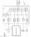
FIG. 1 is an illustration of a robotic system;
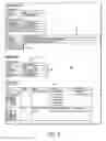
FIG. 2 is an illustration of a user interface to create connectivity groups;
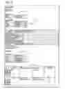
FIG. 3 is an illustration of a user interface to create connectivity rules;
FIG. 4 is an illustration of a user interface used to test connectivity between a remote control station and a robot;
FIG. 5 is an illustration of a user interface similar to FIG. 4 showing an error message;
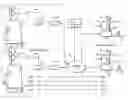
FIG. 6 is a schematic of an electrical system of a robot;
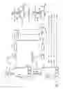
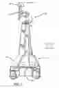
FIG. 7 is side view of the robot;
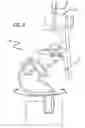
FIG. 8 is a side view of a robot head.
DETAILED DESCRIPTION
Disclosed is a robot system with a robot that has a camera and a remote control station that can connect to the robot. The connection can include a plurality of privileges. The system further includes a server that controls which privileges are provided to the remote control station. The privileges may include the ability to control the robot, join in a multi-cast session and the reception of audio/video from the robot. The privileges can be established and edited through a manager control station. The server may contain a database that defines groups of remote control stations that can be connected to groups of robots. The database can be edited to vary the stations and robots within a group. The system may also allow for connectivity between a remote control station and a robot within a user programmable time window. The system may also allow for connectivity between arbitrary endpoints, including control station to control station connections and robot to robot connections.
Referring to the drawings more particularly by reference numbers, FIG. 1 shows an embodiment of a robot system 10. The robot system 10 includes a plurality of robots 12 each with a base station 14 and a plurality of remote control stations 16. Each remote control station 16 may be coupled to the base station 14 through a network 18. By way of example, the network 18 may be either a packet switched network such as the Internet, or a circuit switched network such has a Public Switched Telephone Network (PSTN) or other broadband system. The base station 14 may be coupled to the network 18 by a modem 20 or other broadband network interface device.
Each remote control station 16 may include a computer 22 that has a monitor 24, a camera 26, a microphone 28 and a speaker 30. The computer 22 may also contain an input device 32 such as a joystick or a mouse. Each control station 16 is typically located in a place that is remote from the robot 12. Although only one robot 12 is shown, it is to be understood that the system 10 may have a plurality of robots 12. In general any number of robots 12 may be controlled by any number of remote stations. For example, one remote station 16 may be coupled to a plurality of robots 12, or one robot 12 may be coupled to a plurality of remote stations 16.
The robot 12 includes a movement platform 34 that is attached to a robot housing 36. Also attached to the robot housing 36 are a camera 38, a monitor 40, a microphone(s) 42 and a speaker 44. The microphone 42 and speaker 30 may create a stereophonic sound. The robot 12 may also have an antenna 46 that is wirelessly coupled to an antenna 48 of the base station 14. The system 10 allows a user at the remote control station 16 to move the robot 12 through the input device 32. The robot camera 38 is coupled to the remote monitor 24 so that a user at the remote station 16 can view a patient. Likewise, the robot monitor 40 is coupled to the remote camera 26 so that the patient can view the user. The microphones 28 and 42, and speakers 30 and 44, allow for audible communication between the patient and the user.
Each remote station computer 22 may operate Microsoft OS software and WINDOWS XP or other operating systems such as LINUX. The remote computer 22 may also operate a video driver, a camera driver, an audio driver and a joystick driver. The video images may be transmitted and received with compression software such as MPEG CODEC. The control station may have general user interfaces that allow for operation of a robot and for multi-casting with other remote stations.
The system 10 includes a server 50 that controls connectivity between the remote control stations 16 and the robots 12. The server 50 includes a database 52. By way of example, the database 52 may be a relational database. The database 52 can allow for groups of remote stations to connect groups of robots. Groups may contain individual robots and control stations. Groups may also contain customers, which represent all robots and control stations belonging to a particular customer. Groups may also contain OEM configurations, which represent all robots and control stations that are sold by a particular 3rd-party OEM distributor. Groups may also contain other groups in a recursive fashion. By way of example, one healthcare entity may have three robots designated ROBOT-1, ROBOT-2 and ROBOT-3 and 5 remote stations designated CS-1, CS-2, CS-3, CS-4 and CS-5. The 3 robots are defined as group R and the remote stations are defined as group S. Rules can be established that allow connectivity between any remote station in group S with any robot in group R.
FIG. 2 shows a user interface 60 that can be used to create and edit groups. The interface includes an “Add Members” field 62 that allows a user to add members to a group. The members can be selected through the “Clients” field 64, “Customers” field 66, “OEM” configuration field 68 or by a “Group” name field 70. The members of the new group are listed in the “Members” field 72. The members can be listed as a string of client serial numbers, customer ids, OEM configuration ids and group ids in a simple XML-like format. In this example, the group includes client control stations CS-2345 and CS-2346. The interface 60 may include an “Add This Group” button 74 that can be selected to add a group to the database.
The interface 60 may include an “Existing Groups” area 76 that allows the user to view existing groups and group members through fields 78 which filter based on the category of group name, OEM, customer or client. Interface area 80 lists each group along with the group members, the person who created the group (with time log), and an indication of whether the group is active. An existing group can be edited by selecting an “Edit” button 82. A history of edits can be viewed by selecting the “History” button 84.
The group data may be stored in the database with the following group connectivity information:
-
- id [int, identity]: Unique numeric ID.
- createID [int]: ID that is shared amongst all group edits in the history chain. This is used to locate the group history. For the initial group creation, the createID is equal to the regular id. All subsequent edits to the group will retain the same createID, but will be given new unique regular ids.
- is Active[bit]: Set to true if group is currently considered active, meaning that it has not been edited and replaced by a new version of the group.
- name [nvarchar]: Friendly name of group. This name appears in any group dropdowns in an advanced page.
- members [text]: String of group members. Contains mixed client machines, customer names, OEM configurations and nested groups.
- membersExpanded [text]: Stores members in an expanded format where all nested groups and OEMs are expanded to list all client machines and customers contained in the groups.
- createdUTC[int]: Timestamp of initial group creation in UTC seconds. When a group is edited, the original group becomes inactive and a new group is created, but the createdUTC timestamp is maintained in the new group.
- modifiedUTC[int]: Timestamp of most recent group modification in UTC seconds. For groups being made inactive due to a group edit, the newly inactive group will have its modified timestamp set to the time of the edit.
- creator[nvarchar]: The user who first created the group. This can be automatically pulled from domain login credentials used to access the various UI pages.
- lastModifiedBy[nvarchar]: The user who last modified the group. This can be automatically pulled from domain login credentials used to access the various UI pages.
- comments[text]: Textual comments attached to group.
FIG. 3 is an interface 90 that can be used to create and edit connectivity rules. The interface 90 includes rule creation filter fields 92 that allow a user to filter the list of systems that appear in the client field XX when creating new rules. There are also fields 94 that allow the user to review existing rules. The connectivity path of a rule can be defined in fields 96 by adding groups, OEMs, customers, and individual robots and control stations to the “From” 98 and “To” 100 fields.
The rules include “From” 98 and “To” 100 fields that define the connectivity path between control stations and robots. The “Priority” field 102 defines how conflicting rules will be resolved. When rules are in conflict, the priority value resolves the ambiguity. If two conflicting rules have the same priority, the rule that was modified most recently wins. The “Privilege Level” field 104 establishes what privileges are allowed in this particular connectivity. By way of example, the system may allow the following privileges:
-
- The ability to operate the robot.
- The ability to accept multi-cast sessions with one or more other remote control stations.
- The ability to be the Host (primary control station CS user) for a multi-cast session with one or more other remote control stations.
- The ability to be a Guest CS in a multi-cast session with one or more other remote control stations.
- The ability to connect directly to a robot (i.e. without being a Guest).
- Disabling of all visible video output and/or audio output from the robot.
- Disabling of saving of media including snapshots and movies from the robot.
- Access to a medical device connected to the robot.
- The ability to view and control auxiliary video sources.
- The ability to use an external handset attached to the robot.
The “Type” field 106 allows the user to specify whether the rule is additive or subtractive. Additive rules can be used to add connectivity. Subtractive rules can be used to selectively remove connectivity in a targeted manner. The “Bidirectional” field 108 allows for connectivity between the From and To members to be unidirectional (“False”) or bidirectional (“True”) which is selectable by the user. The user can set the rule as read-only in the “Read-Only” field 110. Read-only rules always appear at the top of the list when rules are displayed. They require special double confirmation to be edited or deleted.
The user can select a time window for connectivity by entering a start date and time in a “Start Time” field 112 and an end date and time in an “End Time” field 114. The rule can be added by selecting the “Add This Rule” button 116. This allows a user to schedule connectivity in advance, to be enabled at a later date and time.
The From, To, Priority, Privilege and Active data for existing rules can be displayed in an interface area 118. A user can edit an existing rule by selecting an “Edit” button 120 and review edit history by selecting a “History” button 122.
The rules can be stored in the relational database with the following connectivity rule information:
-
- id [int, identity]: Unique numeric ID.
- createID [int]: ID that is shared amongst all rules in the history chain that resulted from edits. This is used to locate the rule history. For the initial rule, the createID is equal to the regular id. All subsequent edits to the rule will retain the same createID, but will be given new unique regular ids.
- priority [int]: Allows establishing precedence between conflicting rules by determining the order in which rules are applied. Higher numbers means the rule will be applied later in the logic chain.
- groupFrom [text]: String of “from” group members.
- Contains mixed client machines, customers and groups.
- For non-bidirectional rules, this represents the source of connectivity, for bidirectional rules it represents both source and destination.
- groupTo [text]: String of “to” group members. Contains mixed client machines, customers and groups. For non-bidirectional rules, this represents the destination of connectivity, for bidirectional rules it represents both source and destination.
- groupFromExpanded [text]: Stores groupFrom in an expanded format where all nested groups and OEMs are expanded to list all client machines and customers contained in the groups.
- groupToExpanded [text]: Stores groupTo in an expanded format where all nested groups and OEMs are expanded to list all client machines and customers contained in the groups.
- privilegeMaskFriendlyNameID [int]: Sets the privilege mask associated with this connectivity rule. This is a link to a privilege table. This can also be set to the special value of −1, which implies that the privilege is not explicitly defined and will be inherited from a rule that is higher up in the logic chain. The privilege table can be transferred to a control station which includes code that can decode the table to determine which privileges are allowed in a connectivity.
- is Active[bit]: Set to true if rule is currently considered active, meaning that it has not expired and has not explicitly been removed or deactivated as the result of being replaced by a new version of the rule following an edit.
- is Bidirectional[bit]: Set to true if rule is bidirectional, meaning that “from” can connect to “to” and vice versa. Set to false for one-way, “from”->“to” connectivity.
- is Readonly[bit]: Set to true if the rule is read only, meaning that it requires double confirmation on edit/delete and always appears at top of rule list display. Set to false for standard rule.
- type[int]: 0=additive connectivity rule, 1=subtractive connectivity rule, 2=privilege-only rule
- startUTC[int]: Defines the start of time window that rule is active in UTC seconds.
- endUTC[int]: Defines the end of time window that rule is active in UTC seconds. For infinite rules, this will be set to 0.
- createdUTC[int]: Timestamp of initial rule creation in UTC seconds. When a rule is edited, the original rule becomes inactive and a new rule is created, but the createdUTC timestamp is maintained in the new rule.
- modifiedUTC[int]: Timestamp of most recent rule modification in UTC seconds. For rules being made inactive due to a rule edit, the newly inactive rule will have its modified timestamp set to the time of the edit.
- creator[nvarchar]: The user who first created the rule. This can be automatically pulled from domain login credentials used to access the various UI pages.
- lastModifiedBy[nvarchar]: The user who last modified the rule. This can be automatically pulled from domain login credentials used to access the various UI pages.
- comments[text]: Textual comments attached to rule. These are required.
The ability to change/add groups and rules can be limited to a select field of users, requiring a password/code for access to the interfaces 60 and 90. The server 50 may provide interfaces that can be accessed by the remote control stations 16 to review connectivity. The pages can provide information on which robots can be accessed by a particular remote control station or which remote control stations can access a specific robot.
The server may provide a tester page that allows a user to test the connectivity between two endpoints. FIG. 4 shows an interface 130 that can be used to test connectivity. The interface 130 includes a “Control Station” field 132 that allows a user to enter a control station name and a “Robot” field 134 that allows the user to enter a robot name. If connectivity is allowed by the server 50 then the interface may indicate a successful connection as in FIG. 5. If connectivity is not allowed by the server 50 then the interface may display a message as shown in FIG. 4. In either case, the interface may display the list of all connectivity rules that applied to the calculation of the connectivity success or failure.
FIG. 6 shows an embodiment of the robot 12. The robot 12 may include a high level control system 150 and a low level control system 152. The high level control system 150 may include a processor 154 that is connected to a bus 156. The bus is coupled to the camera 138 by an input/output (I/O) port 158, and to the monitor 140 by a serial output port 160 and a VGA driver 162. The monitor 40 may include a touchscreen function that allows the patient to enter input by touching the monitor screen.
The speaker 44 is coupled to the bus 156 by a digital to analog converter 164. The microphone 42 is coupled to the bus 156 by an analog to digital converter 166. The high level controller 150 may also contain random access memory (RAM) device 168, a non-volatile RAM device 170 and a mass storage device 172 that are all coupled to the bus 162. The mass storage device 172 may contain medical files of the patient that can be accessed by the user at the remote control station 16. For example, the mass storage device 172 may contain a picture of the patient. The user, particularly a health care provider, can recall the old picture and make a side by side comparison on the monitor 24 with a present video image of the patient provided by the camera 38. The robot antennae 46 may be coupled to a wireless transceiver 174. By way of example, the transceiver 174 may transmit and receive information in accordance with IEEE 802.11b.
The controller 154 may operate with a LINUX OS operating system. The controller 154 may also operate MS WINDOWS along with video, camera and audio drivers for communication with the remote control station 16. Video information may be transceived using MPEG CODEC compression techniques. The software may allow the user to send e-mail to the patient and vice versa, or allow the patient to access the Internet. In general the high level controller 150 operates to control the communication between the robot 12 and the remote control station 16. The controller and the high level controller 150 may be linked to the low level controller 152 by serial ports 176.
The low level controller 152 runs software routines that mechanically actuate the robot 12. For example, the low level controller 152 provides instructions to actuate the movement platform to move the robot 12. The low level controller 152 may receive movement instructions from the high level controller 150. The movement instructions may be received as movement commands from the remote control station. Although two controllers are shown, it is to be understood that the robot 12 may have one controller controlling the high and low level functions.
FIG. 7 shows an embodiment of the robot 12. The robot 12 may include a holonomic platform 150 that is attached to a robot housing 152. The holonomic platform 150 provides three degrees of freedom to allow the robot 12 to move in any direction.
The robot 12 may have a head 154 that supports the camera 38 and the monitor 40. The head 154 may have two degrees of freedom so that the camera 26 and monitor 24 can be swiveled and pivoted as indicated by the arrows.
The system may be the same or similar to a robotic system provided by the assignee InTouch-Health, Inc. of Santa Barbara, Calif. under the trademark RP-7. The system may also be the same or similar to the system disclosed in U.S. Pat. No. 6,925,357 issued Aug. 2, 2005, which is hereby incorporated by reference.
In operation, the robot 12 may be placed in a home, public or commercial property, or a facility where one or more patients are to be monitored and/or assisted. The facility may be a hospital or a residential care facility. By way of example, the robot 12 may be placed in a home where a health care provider may monitor and/or assist the patient. Likewise, a friend or family member may communicate with the patient. The cameras and monitors at both the robot and remote control stations allow for teleconferencing between the patient and the person at the remote station(s).
The robot 12 can be maneuvered through the home, property or facility by manipulating the input device 32 at a remote station 16.
The robot 10 may be controlled by a number of different users. To accommodate for this the robot may have an arbitration system. The arbitration system may be integrated into the operating system of the robot 12. For example, the arbitration technique may be embedded into the operating system of the high-level controller 150.
By way of example, the users may be divided into classes that include the robot itself, a local user, a caregiver, a doctor, a family member, or a service provider. The robot 12 may override input commands that conflict with robot operation. For example, if the robot runs into a wall, the system may ignore all additional commands to continue in the direction of the wall. A local user is a person who is physically present with the robot. The robot could have an input device that allows local operation. For example, the robot may incorporate a voice recognition system that receives and interprets audible commands.
A caregiver is someone who remotely monitors the patient. A doctor is a medical professional who can remotely control the robot and also access medical files contained in the robot memory. The family and service users remotely access the robot. The service user may service the system such as by upgrading software, or setting operational parameters.
Message packets may be transmitted between a robot 12 and a remote station 16. The packets provide commands and feedback. Each packet may have multiple fields. By way of example, a packet may include an ID field a forward speed field, an angular speed field, a stop field, a bumper field, a sensor range field, a configuration field, a text field and a debug field.
The identification of remote users can be set in an ID field of the information that is transmitted from the remote control station 16 to the robot 12. For example, a user may enter a user ID into a setup table in the application software run by the remote control station 16. The user ID is then sent with each message transmitted to the robot.
The robot 12 may operate in one of two different modes; an exclusive mode, or a sharing mode. In the exclusive mode only one user has access control of the robot. The exclusive mode may have a priority assigned to each type of user. By way of example, the priority may be in order of local, doctor, caregiver, family and then service user. In the sharing mode two or more users may share access with the robot. For example, a caregiver may have access to the robot, the caregiver may then enter the sharing mode to allow a doctor to also access the robot. Both the caregiver and the doctor can conduct a simultaneous tele-conference with the patient.
The arbitration scheme may have one of four mechanisms; notification, timeouts, queue and call back. The notification mechanism may inform either a present user or a requesting user that another user has, or wants, access to the robot. The timeout mechanism gives certain types of users a prescribed amount of time to finish access to the robot. The queue mechanism is an orderly waiting list for access to the robot. The call back mechanism informs a user that the robot can be accessed. By way of example, a family user may receive an e-mail message that the robot is free for usage. Tables 1 and 2, show how the mechanisms resolve access request from the various users.
| TABLE I | |||||
| Access | Medical | Command | Software/Debug | Set | |
| User | Control | Record | Override | Access | Priority |
| Robot | No | No | Yes (1) | No | No |
| Local | No | No | Yes (2) | No | No |
| Caregiver | Yes | Yes | Yes (3) | No | No |
| Doctor | No | Yes | No | No | No |
| Family | No | No | No | No | No |
| Service | Yes | No | Yes | Yes | Yes |
| TABLE II | |
| Requesting User |
| Local | Caregiver | Doctor | Family | Service | |
| Current | Local | Not Allowed | Warn current user of | Warn current user of | Warn current user of | Warn current user of |
| User | pending user | pending user | pending user | pending user | ||
| Notify requesting | Notify requesting user | Notify requesting user | Notify requesting | |||
| user that system is in | that system is in use | that system is in use | user that system is in | |||
| use | Set timeout = 5 m | Set timeout = 5 m | use | |||
| Set timeout | Call back | No timeout | ||||
| Call back | ||||||
| Caregiver | Warn current user | Not Allowed | Warn current user of | Warn current user of | Warn current user of | |
| of pending user. | pending user | pending user | pending user | |||
| Notify requesting | Notify requesting user | Notify requesting user | Notify requesting | |||
| user that system is | that system is in use | that system is in use | user that system is in | |||
| in use. | Set timeout = 5 m | Set timeout = 5 m | use | |||
| Release control | Queue or callback | No timeout | ||||
| Callback | ||||||
| Doctor | Warn current user | Warn current user of | Warn current user of | Notify requesting user | Warn current user of | |
| of pending user | pending user | pending user | that system is in use | pending user | ||
| Notify requesting | Notify requesting | Notify requesting user | No timeout | Notify requesting | ||
| user that system is | user that system is in | that system is in use | Queue or callback | user that system is in | ||
| in use | use | No timeout | use | |||
| Release control | Set timeout = 5 m | Callback | No timeout | |||
| Callback | ||||||
| Family | Warn current user | Notify requesting | Warn current user of | Warn current user of | Warn current user of | |
| of pending user | user that system is in | pending user | pending user | pending user | ||
| Notify requesting | use | Notify requesting user | Notify requesting user | Notify requesting | ||
| user that system is | No timeout | that system is in use | that system is in use | user that system is in | ||
| in use | Put in queue or | Set timeout = 1 m | Set timeout = 5 m | use | ||
| Release Control | callback | Queue or callback | No timeout | |||
| Callback | ||||||
| Service | Warn current user | Notify requesting | Warn current user of | Warn current user of | Not Allowed | |
| of pending user | user that system is in | request | pending user | |||
| Notify requesting | use | Notify requesting user | Notify requesting user | |||
| user that system is | No timeout | that system is in use | that system is in use | |||
| in use | Callback | No timeout | No timeout | |||
| No timeout | Callback | Queue or callback | ||||
The information transmitted between the station 16 and the robot 12 may be encrypted. Additionally, the user may have to enter a password to enter the system 10. A selected robot is then given an electronic key by the station 16. The robot 12 validates the key and returns another key to the station 16. The keys are used to encrypt information transmitted in the session.
FIG. 8 shows a robot head 200 that can both pivot and spin the camera 38 and the monitor 40. The robot head 200 can be similar to the robot 12 but without the platform 110. The robot head 200 may have the same mechanisms and parts to both pivot the camera 38 and monitor 40 about a pivot axis 4, and spin the camera 38 and monitor 40 about a spin axis 5. The pivot axis may intersect the spin axis. Having a robot head 200 that both pivots and spins provides a wide viewing area. The robot head 200 may be in the system either with or instead of the mobile robot 12.
While certain exemplary embodiments have been described and shown in the accompanying drawings, it is to be understood that such embodiments are merely illustrative of and not restrictive on the broad invention, and that this invention not be limited to the specific constructions and arrangements shown and described, since various other modifications may occur to those ordinarily skilled in the art.
Claims
What is claimed is:1. A remote controlled, comprising:
a robot that has a camera;
a remote control station that can connect to said robot, said connection including a plurality of privileges;
a server that controls which privileges are provided to said remote control station; and,
a manager control station that can access said server to establish and edit said privileges.
2. The system of claim 1, wherein said robot includes a monitor.
3. The system of claim 2, wherein said robot includes a mobile platform.
4. The system of claim 1, wherein said privileges include an ability to operate said robot.
5. The system of claim 1, wherein said privileges include an ability to participate in a session with another remote station.
6. The system of claim 1, wherein said privileges include an ability to view a video image captured by said robot camera.
7. The system of claim 1, wherein said server includes a privilege map that is transferred to said remote control station.
8. The system of claim 1, wherein said system includes a plurality of robots and a plurality of remote control stations, said server includes a relational that list groups of remote stations that can connect to groups of said robots.
9. The system of claim 1, wherein said connection between said remote control station and said robot is established by a time window.
10. The system of claim 1, wherein said server provides a user interface that allows one or more connectivity rules to be subtracted.
11. A remote controlled robot system, comprising:
a plurality of robots that each have a camera;
a plurality of remote control stations that can connect to said robots;
a server that contains a database that defines groups of said remote stations that can be connected to groups of said robots; and,
a remote control station that can access said server to vary said groups of said remote stations that can be connected to groups of said robots.
12. The system of claim 11, wherein said robot includes a monitor.
13. The system of claim 12, wherein said robot includes a mobile platform.
14. The system of claim 11, wherein said relational database includes at least one connectivity rule.
15. The system of claim 11, wherein said connectivity rule includes a time window to establish connectivity between one or more remote control stations and one or more robots.
16. A remote controller robot system, comprising:
a robot that has a camera;
a remote control station that can connect to said robot; and,
a server that controls connectivity between said remote control station and said robot, said connectivity can be established with a user programmed time window.
17. The system of claim 16, wherein said robot includes a monitor.
18. The system of claim 17, wherein said robot includes a mobile platform.
19. A method for connecting a remote control station to a robot, comprising:
setting at least one connectivity privilege through a manager control station;
connecting a remote control station with a robot that has a camera, the connection being limited to the connectivity privilege.
20. The method of claim 19, wherein the privilege includes an ability to operate the robot.
21. The method of claim 19, wherein the privilege includes an ability to participate in a session with another remote station.
22. The method of claim 19, wherein the privilege includes an ability to view a video image captured by the robot camera.
23. The method of claim 19, further comprising transmitting a video image captured by the robot camera to the remote control station.
24. A method for connecting a remote control station to a robot, comprising:
setting a time window to establish a connection between a remote control station and a robot that has a camera;
connecting a remote control station with the robot at the beginning of the time window.
25. The method of claim 19, further comprising transmitting a video image captured by the robot camera to the remote control station.
Images & Drawings included:
Sources:
- United States Patent and Trademark Office - verify current appl. status at the USPTO↗
Similar patent applications:
- » 20140156078
Server connectivity control for tele-presence robot - » 20190001498
Server connectivity control for tele-presence robot - » 20210220999
Server connectivity control for tele-presence robots - » 20100131103
Server connectivity control for tele-presence robot - » 20160311114
Server connectivity control for a tele-presence robot - » 20150352722
Server connectivity control for a tele-presence robot - » 20180074552
Server connectivity control for a tele-presence robot
Recent applications in this class:
- » 20250042015 2025-02-06
HUMANOID ROBOTICS SYSTEM AND METHODS - » 20240227158 2024-07-11
INDUSTRIAL ROBOT - » 20240131682 2024-04-25
INDUSTRIAL ROBOT - » 20230191588 2023-06-22
Robot - » 20220355465 2022-11-10
Foot structure of legged mobile robot and legged mobile robot - » 20220250231 2022-08-11
HUMANOID ROBOTICS SYSTEM AND METHODS - » 20220016754 2022-01-20
Self-moving robot - » 20210362320 2021-11-25
MOBILE EPIDEMIC PREVENTION AND DISINFECTION ROBOT AND ITS WORKING METHOD - » 20210260749 2021-08-26
GRAPHICAL INTERFACE FOR A REMOTE PRESENCE SYSTEM - » 20210138629 2021-05-13
Pallet robot with scissor lift
Recent applications for this Assignee:
- » 20200273565 2020-08-27
Graphical user interfaces including touchpad driving interfaces for telemedicine devices - » 20200009736 2020-01-09
Social behavior rules for a medical telepresence robot - » 20190375102 2019-12-12
Interfacing with a mobile telepresence robot - » 20190328229 2019-10-31
Telehealth cart that supports a removable tablet with seamless audio/video switching - » 20190190965 2019-06-20
Systems and methods for dynamic bandwidth allocation - » 20190043621 2019-02-07
Modular telehealth cart with thermal imaging and touch screen user interface - » 20180243914 2018-08-30
Protocol for a remotely controlled videoconferencing robot - » 20180099412 2018-04-12
Social behavior rules for a medical telepresence robot - » 20180074552 2018-03-15
Server connectivity control for a tele-presence robot - » 20180071917 2018-03-15
Medical tele-robotic system with a master remote station with an arbitrator