Method for the manufacture of an ejector nozzle tube
US20100224348A1
2010-09-09
12/566,803
2009-09-25
✅ Patent granted
US 8,782,896 B2
2014-07-22
-
-
Christopher Besler
Timothy J. Klima | Shuttleworth & Ingersoll, PLC
2032-05-21
Abstract:
A method for manufacturing an ejector nozzle tube, includes forming an essentially rectangular plate-type blank 1 to have an undulating configuration on two opposite edge areas 2, 3, subsequently bending the blank around an axis 4, which is arranged centrically and parallel to the edge areas 2, 3, with the edge areas 2, 3 being superposed and subsequently joining the edge areas by point connections 6, providing for the formation of ejector nozzles 5 between the point connections.
Assignee:
- ROLLS-ROYCE DEUTSCHLAND LTD & CO KG 222 🇩🇪 Blankenfelde-Mahlow, Germany
- Rolls-Royce Deutschland Ltd & Co KG 231 🇩🇪 , Germany
Applicant:
Interested in similar patents?
Get notified when new applications in this technology area are published.
Classification:
F01D25/12 » CPC further
Component parts, details, or accessories, not provided for in, or of interest apart from, other groups; Cooling ; Heating; Heat-insulation Cooling
Y02T50/60 » CPC further
Aeronautics or air transport Efficient propulsion technologies, e.g. for aircraft
Y02T50/60 » CPC further
Aeronautics or air transport Efficient propulsion technologies, e.g. for aircraft
Y10T29/49366 » CPC further
Metal working; Method of mechanical manufacture; Heat exchanger or boiler making Sheet joined to sheet
Y10T29/49401 » CPC further
Metal working; Method of mechanical manufacture Fluid pattern dispersing device making, e.g., ink jet
Y10T29/49428 » CPC further
Metal working; Method of mechanical manufacture Gas and water specific plumbing component making
Y10T29/49432 » CPC further
Metal working; Method of mechanical manufacture; Gas and water specific plumbing component making Nozzle making
F28F1/02 IPC
Tubular elements; Assemblies of tubular elements Tubular elements of cross-section which is non-circular
B21D5/00 IPC
Bending sheet metal along straight lines, e.g. to form simple curves
B23P17/00 IPC
Metal-working operations, not covered by a single other subclass or another group in this subclass
B05B1/26 IPC
Nozzles, spray heads or other outlets, with or without auxiliary devices such as valves, heating means with means for mechanically breaking-up or deflecting the jet after discharge, e.g. with fixed deflectors; Breaking-up the discharged liquid or other fluent material by impinging jets
F05D2250/184 » CPC further
Geometry; Two-dimensional patterned sinusoidal
F01D25/18 » CPC further
Component parts, details, or accessories, not provided for in, or of interest apart from, other groups Lubricating arrangements
B21D51/06 » CPC further
Making hollow objects characterised by the structure of the objects folded objects
B21D53/06 » CPC further
Making other particular articles heat exchangers , e.g. radiators, condensers of metal tubes
B21D51/10 » CPC further
Making hollow objects characterised by the structure of the objects conically or cylindrically shaped objects
F05D2250/182 » CPC further
Geometry; Two-dimensional patterned crenellated, notched
B64D33/10 » CPC further
Arrangements in aircraft of power plant parts or auxiliaries not otherwise provided for of power plant cooling systems Radiator arrangement
F05D2250/183 » CPC further
Geometry; Two-dimensional patterned zigzag
F05D2260/20 » CPC further
Function Heat transfer, e.g. cooling
F05D2250/181 » CPC further
Geometry; Two-dimensional patterned ridged
F05D2260/601 » CPC further
Function; Fluid transfer using an ejector or a jet pump
F05D2250/18 » CPC further
Geometry; Two-dimensional patterned
B05B15/00 IPC
Details of spraying plant or spraying apparatus not otherwise provided for; Accessories
F02K1/36 » CPC main
Plants characterised by the form or arrangement of the jet pipe or nozzle; Jet pipes or nozzles peculiar thereto having an ejector
Description
This application claims priority to German Patent Application DE 10 2009 011 452.1 filed Mar. 3, 2009, the entirety of which is incorporated by reference herein.
This invention relates to a method for the manufacture of an ejector nozzle tube.
Ejector nozzle tubes are used in the state of the art to introduce a second fluid into a first fluid flow, for example to accelerate the latter. Here, the ejector nozzle tube usually extends transversely to the flow direction within a flow duct and is provided on the outflow side with openings enabling the second fluid flow to issue.
The ejector nozzle tube is usually supplied from one side, so that the flow of second fluid within the ejector nozzle tube extends in the longitudinal direction of the latter. This means that the individual exit openings or exit nozzles are differently applied with the second fluid and that a different fluid pressure exists therein. This entails considerable disadvantages in that the second fluid is irregularly introduced along the ejector nozzle tube, thereby failing to produce the desired effects in the first fluid flow throughout the entire cross-section thereof.
In a broad aspect, the present invention provides a method for the manufacture of an ejector nozzle tube which, while being simply designed and easily and cost-effectively applicable, avoids the disadvantages of the state of the art and provides for flow optimization.
According to the present invention, provision is therefore made for an ejector nozzle tube made of a rectangular sheet or plate-type blank. This blank is imprinted on two opposite side or edge areas to produce an undulated structure.
Subsequently, the blank is bent or folded around its center area. Thus, a flow cross-section is produced which is tubular and serves for the introduction of the fluid. In the process, the two undulatingly imprinted or formed rim or edge areas are superposed. Since the edge areas do not fully conformally contact each other, areas forming ejector nozzles are produced by interference or displacement of the undulated structure. Between the ejector nozzles, the edge areas are joined by point connections, for example by spot welding.
In a particularly favorable development of the present invention, provision is made for a part-circular cross-section of the center bending area. Therefore, the ejector nozzle tube according to the present invention can be provided with an aerodynamically optimized, drop-shaped cross-section, which is flat in the area of the superposed edges forming the ejector nozzles and part-circular at the inflow side. This provides for a flow optimization of the above-described first fluid flow. The latter is only insignificantly disturbed by the ejector nozzle tube according to the present invention. Thus, provision is made for a laminar flow over a wide range along the surface of the ejector nozzle tube according to the present invention, with no undesired swirling or aerodynamic drag occurring.
According to the present invention, it can be particularly favorable to form the undulated edge areas with different geometry relative to each other. This enables the individual ejector nozzles formed by superposing the two edge areas to be specifically shaped. Thus, provision is also made for alternatingly varying individual ejector nozzles as regards the jet exit direction, with the nozzles being alternatingly upwardly or downwardly orientable.
According to the present invention, the edge areas can be rectilinear or structured. Accordingly, undulation or similar can also be provided in the area of the edges, thereby enabling the individual ejector nozzles to be saliently or recessedly arranged relative to each other upon superposing the two edge areas. It can thus be favorable to provide ejector nozzle rows which are offset relative to each other.
According to the present invention, the inventive ejector nozzle tube is preferably used in a flow duct of a heat exchanger to accelerate the flow of the first fluid through the flow duct of the heat exchanger by introducing the second fluid into the ejector nozzle tube if the flow velocity in the flow duct is not sufficient.
In the following the present invention is more fully described in light of the accompanying drawings showing a preferred embodiment. In the drawings,
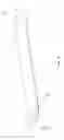
FIG. 1 is a simplified perspective representation of the manufacturing process,
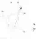
FIG. 2 is a perspective representation, analogically to FIG. 1, of the finished ejector nozzle tube,
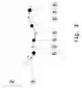
FIG. 3 is a detailed view, showing detail A of FIG. 2,
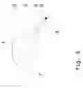
FIG. 4 is a top view of the edge area as per FIGS. 1 and 2,
FIGS. 5-7 are sectional views along the lines B-B (FIG. 5), C-C (FIG. 6) and D-D (FIG. 7).
The ejector nozzle tube according to the present invention is made of an essentially rectangular sheet or plate-type blank 1. This blank has edge areas 2, 3 which are arranged opposite to each other. Firstly, these are provided with an undulated imprint. The edge areas can either be rectilinear or undulated, as shown in FIG. 4. Preferably, the undulated imprint or deformation, which is shown in FIG. 1, is selected such that individual undulation peaks or undulation valleys are produced in the longitudinal direction of the ejector nozzle tube, with the two edge areas 2, 3 being not fully conformally dimensioned or formed relative to each other.
In a further operation, the blank 1 is bent or folded in its center area to produce, as shown in the figures, the part-circular cross-section around an axis 4, with the latter assuming the position of a center axis at least for the inflow area of the injector nozzle tube.
Due to the undulated structure of the two edge areas 2, 3, superposition of the latter produces zones in which the two edge areas converge toward or contact each other. These zones are joined to each other by point connections 6 (for example spot welding). Between the point connections 6, zones occur in which the two edge areas 2, 3 diverge away from and do not conformally contact each other, but are apart from each other. Thus, provision is made for the formation of ejector nozzles 5 (see FIG. 3, for example). The flow introduced into the interior of the ejector nozzle tube can issue through these ejector nozzles 5, as shown in FIGS. 5 and 7 (secondary flow 9). The structuring enables the exit direction of the individual ejector nozzles 5 to be varied, so that the ejector nozzles 5 are, for example, alternatingly oriented slightly upward or downward, respectively. Furthermore, the distance of the exit cross-section of the ejector nozzles from the axis 4 is variable, as conveyed by FIG. 4. Consequently, individual nozzles will project farther than other ejector nozzles 5, which are slightly setback.
In FIGS. 5-7, reference numeral 8 indicates the main flow enveloping the ejector nozzle tube. The aerodynamically favorable design provides for an optimized course of the main flow 8.
The ejector nozzle tube according to the present invention is particularly suitable for application in oil coolers of aircraft. Such oil coolers are cooled by the inflowing air. If the aircraft is in a phase of low airspeed, for example during taxiing or in the initial take-off phase, the quantity of air flowing through the oil cooler is inadequate. Accordingly, the cooling effect produced is only low. Therefore, is its particularly advantageous to provide the flow duct of the oil cooler with an ejector nozzle tube according to the present invention. Introducing a secondary flow enables the main flow to be correspondingly accelerated, thereby providing for an adequate cooling effect by the air additionally supplied by the secondary flow, in spite of the low inflow velocity.
The acceleration effect by the flow issuing from the ejector nozzles results from friction with the particles of the main flow. Since the exit velocity from the ejector nozzles is far higher than the velocity of the main flow, the particles of the main flow are entrained and thereby accelerated. This leads to a suction effect which accelerates the entire main flow.
According to the present invention, the effect described is achieved with an ejector nozzle tube of very simple design, which is cost-effectively producible with simplest means. It is only required that a blank be imprinted, folded and joined by individual spot welds. These operations are implementable with minimum production effort.
The cross-sectional shape according to the present invention, which is an airfoil-type profile, provides for particular optimization of flow. The configuration of the edge area, and the ejector nozzles resulting therefrom, provides for an increase in efficiency over that of state-of-the-art tubular ejector nozzle tubes. This increase is provided in particular by the main flow 8 (see FIGS. 5 and 7) passing in direct contact with and essentially parallel to the secondary flow 9 exiting from the ejector nozzles 5.
Besides simplified manufacture (compared with the state of the art), substantial material saving is obtained in that a simple sheet bending part can be used, instead of an expensive tubular design with welded-on tube fittings. The already described increase in efficiency of more than 70% and the producibility of more than 10% higher volumes of secondary flow than in the state of the art yields an increase in efficiency of 80 to 90% for an oil cooler of the type described.
LIST OF REFERENCE NUMERALS
- 1 Blank
- 2, 3 Edge area
- 4 Axis
- 5 Ejector nozzle
- 6 Point connection
- 7 Center bending area
- 8 Main flow
- 9 Secondary flow
Claims
What is claimed is:1. A method for manufacturing an ejector nozzle tube, comprising:
forming an essentially rectangular sheet blank to have an undulating configuration on two opposite edge areas;
subsequently bending the sheet around an axis, which is arranged centrally and parallel to the edge areas to superpose the edge areas; and
subsequently joining portions of the superposed edge areas which converge toward each other with point connections to form ejector nozzles between the point connections from the superposed edge areas which diverge from each other.
2. The method of claim 1, and further comprising forming a center bending area to have a part-circular cross-section.
3. The method of claim 2, and further comprising forming the undulated edge areas with different geometries relative to each other.
4. The method of claim 2, wherein the edge areas are rectilinear.
5. The method of claim 2, wherein the edge areas are structured.
6. The method of claim 1, wherein the ejector nozzles are arranged in rows which are offset relative to each other.
7. The method of claim 1, and further comprising forming the undulated edge areas with different geometries relative to each other.
8. The method of claim 1, wherein the edge areas are rectilinear.
9. The method of claim 1, wherein the edge areas are structured.
10. The method of claim 1, wherein the joining step is by welding.
11. An ejector nozzle tube manufactured in accordance with the method of claim 1.
12. A heat exchanger comprising an ejector nozzle tube in accordance with claim 11, the ejector nozzle tube positioned in a flow duct of the heat exchanger for the introduction of a secondary flow which influences a main flow through the flow duct.
13. An ejector nozzle tube manufactured in accordance with the method of claim 2.
14. A heat exchanger comprising an ejector nozzle tube in accordance with claim 13, the ejector nozzle tube positioned in a flow duct of the heat exchanger for the introduction of a secondary flow which influences a main flow through the flow duct.
Images & Drawings included:


Sources:
- United States Patent and Trademark Office - verify current appl. status at the USPTO↗
Recent applications in this class:
- » 20250230782 2025-07-17
Eductor Jet Engine - » 20190078535 2019-03-14
Swirling flow eductor system and method - » 20150000289 2015-01-01
Gas ejection cone for aircraft turbojet engines - » 20130087632 2013-04-11
GAS TURBINE ENGINE EXHAUST EJECTOR NOZZLE WITH DE-SWIRL CASCADE - » 20100199673 2010-08-12
Gas turbine engine with eductor and eductor flow distribution shield - » 20090320446 2009-12-31
Performance improvements for pulse detonation engines - » 20050155341 2005-07-21
Axisymmetric flap on gas turbine exhaust centerbody - » 13310325 2017-02-14
Centrifugal turbomachines having extended performance ranges
Recent applications for this Assignee:
- » 20230015929 2023-01-19
LEAN BURN INJECTOR WITH SUPPLY LINE SWITCHING - » 20220316709 2022-10-06
Combustor with improved aerodynamics - » 20220178543 2022-06-09
Combustor with improved aerodynamics - » 20220178542 2022-06-09
Combustor with improved aerodynamics - » 20220178541 2022-06-09
Lean burn combustor - » 20210301679 2021-09-30
In-flight monitoring of aero engine health - » 20210301678 2021-09-30
Gas turbine engine - » 20210222630 2021-07-22
TURBOSHAFT - » 20210222617 2021-07-22
Turboshaft gas turbine engine and expansion ratio relationship - » 20210179282 2021-06-17
Aircraft hybrid propulsion system