REPORTING CIRCUIT BREAKER AND SYSTEM
US20100256934A1
2010-10-07
12/418,182
2009-04-03
Abstract:
A novel load-reporting circuit breaker having load sensing and a wireless transmitter providing a corresponding load signal and an identification signal of the distribution panel(s) and circuit. A receiver common for several or all load-reporting circuit breakers provides a signal corresponding to the received individual circuit loads and corresponding identifications or address data, to an accounting device, e.g. computer that aggregates all loads for each user to which such load is allocated.
Interested in similar patents?
Get notified when new applications in this technology area are published.
Classification:
G01R31/3278 » CPC main
Arrangements for testing electric properties; Arrangements for locating electric faults; Arrangements for electrical testing characterised by what is being tested not provided for elsewhere; Testing of circuit interrupters, switches or circuit-breakers of low voltage devices, e.g. domestic or industrial devices, such as motor protections, relays, rotation switches of relays, solenoids or reed switches
H02J13/00036 » CPC further
Circuit arrangements for providing remote indication of network conditions, e.g. an instantaneous record of the open or closed condition of each circuitbreaker in the network; Circuit arrangements for providing remote control of switching means in a power distribution network, e.g. switching in and out of current consumers by using a pulse code signal carried by the network; Systems characterised by the controlled or operated power network elements or equipment, the power network elements or equipment not otherwise provided for the elements or equipment being or involving switches, relays or circuit breakers
H02J13/0075 » CPC further
Circuit arrangements for providing remote indication of network conditions, e.g. an instantaneous record of the open or closed condition of each circuitbreaker in the network; Circuit arrangements for providing remote control of switching means in a power distribution network, e.g. switching in and out of current consumers by using a pulse code signal carried by the network for single frequency AC networks characterised by transmission structure between the control or monitoring unit and the controlled or monitored unit with direct transmission between the control or monitoring unit and the controlled or monitored unit using radio means
G01R22/063 » CPC further
Arrangements for measuring time integral of electric power or current, e.g. electricity meters by electronic methods; Details of electronic electricity meters related to remote communication
H01H9/167 » CPC further
Details of switching devices, not covered by groups - ; Indicators for switching condition, e.g. "on" or "off" Circuits for remote indication
H01H71/04 » CPC further
Details of the protective switches or relays covered by groups - Means for indicating condition of the switching device
H02J13/00022 » CPC further
Circuit arrangements for providing remote indication of network conditions, e.g. an instantaneous record of the open or closed condition of each circuitbreaker in the network; Circuit arrangements for providing remote control of switching means in a power distribution network, e.g. switching in and out of current consumers by using a pulse code signal carried by the network characterised by information or instructions transport means between the monitoring, controlling or managing units and monitored, controlled or operated power network element or electrical equipment using wireless data transmission
Y02E60/00 » CPC further
Enabling technologies; Technologies with a potential or indirect contribution to GHG emissions mitigation
Y02E60/00 » CPC further
Enabling technologies; Technologies with a potential or indirect contribution to GHG emissions mitigation
Y04S10/18 » CPC further
Systems supporting electrical power generation, transmission or distribution using switches, relays or circuit breakers, e.g. intelligent electronic devices [IED]
Y04S40/126 » CPC further
Systems for electrical power generation, transmission, distribution or end-user application management characterised by the use of communication or information technologies, or communication or information technology specific aspects supporting them characterised by data transport means between the monitoring, controlling or managing units and monitored, controlled or operated electrical equipment using wireless data transmission
G01R21/00 IPC
Arrangements for measuring electric power or power factor
G01R19/00 IPC
Arrangements for measuring currents or voltages or for indicating presence or sign thereof
Description
FIELD OF THE INVENTION
This application relates generally to a power distributions systems and user billing, more specifically, to multi-user power distribution systems connected to single circuit breaker panels and the associated load reporting circuit breaker.
BACKGROUND
The increasing demand for conservation of resources and accounting for the particular use of those resources, specifically electricity, encourages building owners to retrofit buildings with associated meters and corresponding individual electricity distribution panels each tenant or account, with the intent of back-charging the tenant for excessive power consumption. However, the power distribution methods outlined in the National Electric Code require particular methods and equipment which may not be available or cost-effective for retrofitting a multi-tenant building.
In commercial facilities, the building space is divided into smaller units for the individual tenants, for whom the power consumption should be billed accordingly. However, due to the constant turnover of tenants and the resulting continual renovation and redesign of building spaces make re-routing and re-allocation of power branch circuits to new or different distribution panels each to be dedicated to the particular tenant, necessary, significant and recurring expense and inconvenience, including interruptions to the other tenants.
SUMMARY
The present invention provides a power distribution system providing multiple branch circuits from a common distribution panel to which different and individually billed tenants, users or loads are connected and corresponding different power consumption is accounted individually and/or as a total for multiple circuits for each tenant, user or load. Each branch circuit has a corresponding circuit breaker transmitting an individual identification or address and load power drain signal to be received by a receiver, sorted and allocated (e.g. according to a tenant allocation schedule), wherein each of several tenants can be billed for only the specific power distribution circuits associated with their building space. As the tenants' usage changes, the novel system according to the present invention provides flexibility to add or delete additional circuits from the accounting and billing without necessitating distribution panel changes.
One embodiment of the present invention further includes a novel load-reporting circuit breaker having load (typically current) sensing and a wireless transmitter providing a corresponding load signal and an address unique to the distribution panel(s) and circuit. A receiver common for several or all load-reporting circuit breakers provides a signal including the individual circuit loads and corresponding identifications or address data, to an accounting device, e.g. computer that aggregates all loads for each user to which such loads are allocated. As the tenant needs change, the allocation of circuits may similarly change with minimal and possibly no changes to the physical layout. Other load consumption information, e.g. common utilities that are separately monitored according to the present invention may be allocated to the individual tenants according to a predetermined schedule.
BRIEF DESCRIPTION OF DRAWINGS
The drawings, when considered in connection with the following description, are presented for the purpose of facilitating an understanding of the subject matter sought to be protected.
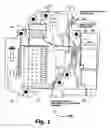
FIG. 1 is plan view of one embodiment of the novel circuit breaker device as disclosed herein; and
FIG. 2 is a block diagram of one embodiment of the system according to the present invention including the circuit breaker of FIG. 1.
DETAILED DESCRIPTION
Referring to the exemplary embodiment 50 of the reporting circuit breaker according to the present invention, a housing 52 provides a circuit breaker which typically engages a distribution panel by protrusion 42, and a power distribution connector 56 (and ultimately connected to service 106, FIG. 2), which in turn is connected to branch connector 58 with movable internal contacts, including a bimetallic member 60, responsive to a manual actuator lever 62 and to the a solenoid 64, wherein the bimetallic member 60 and/or solenoid 64 are typically responsive to overload conditions and are connected to cause internal contacts to interrupt a circuit connection between power distribution connector 56 and branch circuit connector. According to the present invention, the exemplary circuit breaker 50 further includes a current sensor 70 disposed to provide a signal on connections 74 to a wireless transmitter 80 according to the power load imposed on the branch circuit by externally connected equipment (not shown). The transmitter 80 provides a wireless signal corresponding to the current sensor 70 signal and a identification signal unique to the particular circuit breaker 50 and therefore to the branch circuit to which the circuit breaker is connected, or unique to the tenant. Alternately, each circuit breaker may be programmable to have an identification corresponding to the particular tenant for which the connected branch circuit is associated (and therefore to be billed for power consumption). The current sensor typically comprises a commercially available current sensor, e.g. a current transformer, etc., capable of monitoring current in the range of current corresponding to the load rating of the circuit breaker 50.
In a typical application 100, the individual circuit breakers 50A-50H are disposed in a typical distribution panel 102 and are connected to a power source, such as from a power line pole, street connection, etc. via a service 106. The individual circuit breakers 50A-50H are connected to corresponding branch circuits 108A-108H having loads (not shown) which impose a power drain monitored by each circuit breaker 50A-50H and sending a corresponding wireless transmission 112A-112H to be received 114 by receiver/accumulator 110, which is in turn sends the data signals to a computer 120 via connection 118.
In exemplary one facility embodiment, circuits 108A, 108C and 108E may be associated with tenant A, while circuits 108B, 108D and 108F may be associated with tenant B, and so forth. In the case that each circuit breaker has unique individual identifications, the receiver/accumulator 110 or the computer 120 will be programmed to combine the signals, and with them the value for the power drawn in the associated branch circuits, together for the corresponding tenant, and further combine signals from other circuit breakers for other corresponding tenants. In the case where circuit breakers for the same tenant are programmed to provide an identical identification signal for the corresponding tenant, the receiver/accumulator 110 and/or the computer 120 provides a tenant accounting of power drain for received signals having the same identification.
The transmission and/or telemetry protocols, modes, formats, etc. used in the embodiments of the present invention may include available protocols, modes, formats, etc. available to those skilled in the art. Similarly, the transmitters 80, receiver/accumulator 110 and computer 120 may include transmitters, receiver and computer available to those skilled in the art. Moreover, the reporting circuit breakers according to the present invention may be located in a plurality of distribution panels and the resulting transmitted signals received by a common receiver, or plural receivers functioning as described above and having signals combined by or before the computer 120. Furthermore, other loads common to the facility or a number of tenants may be managed and accounted as a separate ‘tenant’. The present invention may apply to all voltages, phases, and Hertz. Modifications and substitutions made by one skilled in the art are within the scope of the present invention, which is not to be limited except by the claims that follow.
Claims
What is claimed is:1. A circuit breaker, comprising:
a plurality of terminals;
a circuit closure device connected to provide a continuous electrical circuit between at least two of said plurality of terminals, and to interrupt said continuous electrical circuit in response to a current flow between said plurality of terminals in excess of a selected threshold value;
a current monitoring device providing a signal in response to a flow of current in said continuous electrical circuit; and
a transmitter providing a radiated signal in response to said flow of current and a corresponding circuit breaker identification.
2. The circuit breaker of claim 1, further including a housing including at least said circuit closure device, said current monitoring device and said transmitter.
3. The circuit breaker of claim 1, wherein said current monitoring device comprises a current transformer, current measuring device.
4. The circuit breaker of claim 1, wherein said transmitter provide a unique identification signal.
5. The circuit breaker of claim 1, wherein said transmitter provides an identification signal unique to a tenant.
6. A load monitoring system for multiple users receiving electrical power from at least one common circuit breaker panel, comprising:
a plurality of circuit breakers disposed within said common circuit breaker panel each connected to a corresponding circuit for diverse users, and each of said plurality of circuit breakers including a current signal transmitter including a wireless identification signal and including a signal corresponding to a flow of current through that circuit breaker;
a wireless signal receiver providing a received current signal and a corresponding circuit identification signal corresponding to each of said plurality of circuit breakers; and
a user load accounting device connected to receive said signals corresponding to the flow of current through circuits of a particular user.
7. The load monitoring system of claim 6, wherein said accounting device forms aggregate value of current used by said user.
8. The load monitoring system of claim 7, wherein each of said plurality of circuit breakers send unique identification signals, and said user load accounting device determines a total user load according to said unique identification signals.
9. The load monitoring system of claim 7, wherein each of said plurality of circuit breakers sends identification signals corresponding to a particular user, and said user load accounting device determines a total user load according to the identification signal corresponding to said particular user.
10. A method of managing electric power distribution in a facility, comprising:
providing a plurality of branch circuits from a common source to at least one facility tenant;
monitoring the power load of at least one of said branch circuit through a corresponding circuit breaker;
wirelessly transmitting a reporting signal corresponding to the monitored power load of said branch circuit and corresponding to a branch circuit identification signal;
receiving said reporting signal;
determining power consumption according to said reporting signal; and
accumulating an aggregate determined power from said determined power consumption over a period of time.
11. The method of claim 10, wherein said monitoring comprises monitoring a plurality of circuits, said step of determining comprises determining power consumption according to a plurality of reporting signals.
12. The method of claim 10, wherein
said providing a plurality of branch circuits comprises providing a plurality of branch circuits to at least two different facility tenants, and
said determining an aggregate determined power consumption comprises determining an aggregate determined power consumption for each facility tenant according to said reporting signal.
13. The method of claim 12, further including
transmitting a different identification signal for each branch circuit, and
identifying all identification signals for said facility tenant, and
determining aggregate power consumption according to said identification signals for said facility tenant
14. The method of claim 12, further including
wirelessly transmitting an identical identification signal for each branch circuit associated with said facility tenant, and
determining aggregate power consumption according to said identical identification signal for the corresponding said facility tenant.
Images & Drawings included:


Sources:
- United States Patent and Trademark Office - verify current appl. status at the USPTO↗
Similar patent applications:
- » 20130144768
Reporting circuit breaker and system - » 20140236787
REPORTING CIRCUIT BREAKER AND SYSTEM
Recent applications in this class:
- » 20250164558 2025-05-22
ABNORMALITY DETECTION DEVICE AND ABNORMALITY DETECTION METHOD - » 20250138090 2025-05-01
Battery System Capable of Pack Relay Diagnosis and Vehicle Comprising the Same - » 20250130281 2025-04-24
Cloud-Based Line Differential Relays Dynamic Testing - » 20250102577 2025-03-27
Energy Storage Apparatus and Failure Diagnosis Method - » 20250093417 2025-03-20
ELECTRONIC CONTROL DEVICE AND ELECTRONIC CONTROL METHOD - » 20250027997 2025-01-23
Stuck-Closed Diagnosis Method and Battery System Using the Same - » 20250004052 2025-01-02
Leakage current detection and interruption device for power cord and related electrical connectors and electrical appliances - » 20240426915 2024-12-26
DETECTING WELDED RELAY CONTACTS USING SPANNER VOLTAGE MEASUREMENT - » 20240426914 2024-12-26
DETECTING WELDED RELAY CONTACTS USING CONTACT CLOSE TIME MEASUREMENT - » 20240426913 2024-12-26
DETECTING WELDED RELAY CONTACTS USING MEASUREMENT AFTER CURRENT BREAK