Bezel illumination for digital devices
US20100289666A1
2010-11-18
12/582,401
2009-10-20
✅ Patent granted
US 8,823,541 B2
2014-09-02
-
-
Daryl Pope
John L. Rogitz
2031-10-18
Abstract:
First, a user may select an illumination color for a bezel framing a display of an electronics device. Second, the illumination of a digital picture frame may be established based on sensed motion nearby and/or ambient light. Third, the color of a user interface presented on a display can be established to match the color of the room in which the display is disposed, as indicated by colorimetry from a camera.
Inventors:
- Steven Friedlander 74 🇺🇸 San Diego, CA, United States
- Robert Hardacker 80 🇺🇸 Escondido, CA, United States
- Rafael Calderon 18 🇺🇸 San Diego, CA, United States
- STEVEN RICHMAN 54 🇺🇸 SAN DIEGO, CA, United States
Assignee:
- Sony Corporation 43,269 🇯🇵 Tokyo, Japan
- SONY ELECTRONICS INC. 1,728 🇺🇸 Park Ridge, NJ, United States
Applicant:
Interested in similar patents?
Get notified when new applications in this technology area are published.
Classification:
H04N1/00347 » CPC main
Scanning, transmission or reproduction of documents or the like, e.g. facsimile transmission; Details thereof; Connection or combination of a still picture apparatus with another apparatus, e.g. for storage, processing or transmission of still picture signals or of information associated with a still picture with another still picture apparatus, e.g. hybrid still picture apparatus
G06F3/147 » CPC further
Input arrangements for transferring data to be processed into a form capable of being handled by the computer; Output arrangements for transferring data from processing unit to output unit, e.g. interface arrangements; Digital output to display device ; Cooperation and interconnection of the display device with other functional units using display panels
H04N1/0035 » CPC further
Scanning, transmission or reproduction of documents or the like, e.g. facsimile transmission; Details thereof User-machine interface; Control console
H04N21/41407 » CPC further
Selective content distribution, e.g. interactive television or video on demand [VOD]; Client devices specifically adapted for the reception of or interaction with content, e.g. set-top-box [STB]; Operations thereof; Structure of client; Structure of client peripherals; Specialised client platforms, e.g. receiver in car or embedded in a mobile appliance embedded in a portable device, e.g. video client on a mobile phone, PDA, laptop
H04N21/42202 » CPC further
Selective content distribution, e.g. interactive television or video on demand [VOD]; Client devices specifically adapted for the reception of or interaction with content, e.g. set-top-box [STB]; Operations thereof; Structure of client; Structure of client peripherals; Input-only peripherals , e.g. global positioning system [GPS] environmental sensors, e.g. for detecting temperature, luminosity, pressure, earthquakes
H04N21/4223 » CPC further
Selective content distribution, e.g. interactive television or video on demand [VOD]; Client devices specifically adapted for the reception of or interaction with content, e.g. set-top-box [STB]; Operations thereof; Structure of client; Structure of client peripherals; Input-only peripherals , e.g. global positioning system [GPS] Cameras
H04N21/4318 » CPC further
Selective content distribution, e.g. interactive television or video on demand [VOD]; Client devices specifically adapted for the reception of or interaction with content, e.g. set-top-box [STB]; Operations thereof; Processing of content or additional data, e.g. demultiplexing additional data from a digital video stream; Elementary client operations, e.g. monitoring of home network or synchronising decoder's clock; Client middleware; Generation of visual interfaces for content selection or interaction ; Content or additional data rendering by altering the content in the rendering process, e.g. blanking, blurring or masking an image region
G09G2310/0232 » CPC further
Command of the display device; Addressing, scanning or driving the display screen or processing steps related thereto Special driving of display border areas
G09G2320/0626 » CPC further
Control of display operating conditions; Adjustment of display parameters for control of overall brightness
G09G2320/0666 » CPC further
Control of display operating conditions; Adjustment of display parameters for control of colour parameters, e.g. colour temperature
G09G2330/022 » CPC further
Aspects of power supply; Aspects of display protection and defect management; Details of power systems and of start or stop of display operation; Power management, e.g. power saving in absence of operation, e.g. no data being entered during a predetermined time
G09G2354/00 » CPC further
Aspects of interface with display user
G09G2360/144 » CPC further
Aspects of the architecture of display systems; Detecting light within display terminals, e.g. using a single or a plurality of photosensors the light being ambient light
G09G2380/16 » CPC further
Specific applications Digital picture frames
H04N5/58 » CPC further
Details of television systems; Receiver circuitry for the reception of television signals according to analogue transmission standards; Control of contrast or brightness in dependence upon ambient light
G09F9/33 IPC
Indicating arrangements for variable information in which the information is built-up on a support by selection or combination of individual elements in which the desired character or characters are formed by combining individual elements being semiconductor devices, e.g. diodes
G08B5/36 IPC
Visible signalling systems, e.g. personal calling systems, remote indication of seats occupied using electric transmission; using electromagnetic transmission using visible light sources
H04N7/18 IPC
Television systems Closed circuit television systems, i.e. systems in which the signal is not broadcast
G08B5/22 IPC
Visible signalling systems, e.g. personal calling systems, remote indication of seats occupied using electric transmission; using electromagnetic transmission
Description
I. FIELD OF THE INVENTION
The present invention relates a feedback system implemented into a display device involving a mounted light source whose brightness is controlled by a mounted camera sending information to a processor within the display device.
II. BACKGROUND OF THE INVENTION
Digital photo frames have been provided which can present, on a computer-controlled display, digital photographs. These frames mimic in size and shape traditional photo frames, but have the advantages of allowing users to rapidly view multiple photos in succession without flipping through a hard copy album, and allowing users to quickly and easily change the image that is presented in the frame without having to remove the back of the frame and swap hard copy photos.
As understood herein, enhancements can be provided to the bezel framing the digital photo display. Moreover, present principles understand that in general, the illumination of bezels in consumer electronics devices may be improved for visual appeal and effect.
SUMMARY OF THE INVENTION
In one embodiment, a digital photo frame assembly includes a frame, a display bordered by the frame, and one or more light sources such as LEDs are positioned to internally illuminate the frame. A computer readable storage medium bearing digital still images is provided, and a processor causes images from the medium to be presented on the display. The processor establishes an illumination of the frame based on a motion signal and/or an ambient light signal received by the processor.
In some implementations the assembly can include a motion sensor communicating with the processor and sending a motion signal to the processor in response to motion of an object relative to the assembly. The processor establishes the illumination of the frame in response to the motion signal. In addition or alternatively, the assembly can include a light sensor communicating with the processor and sending an ambient light signal to the processor representative of a level of ambient light external to the assembly, with the processor establishing the illumination of the frame in response to the ambient light signal. The processor may incrementally control the illumination from lighter to darker along a continuum based on the amount of ambient light.
In another embodiment, an electronic apparatus has a video display, a camera positioned to image a space in front of the display, and a processor receiving signals from the camera and responsive thereto establishing a color of a user interface presented on the display, and/or a color of a bezel framing the display. The processor may use colorimetry information from the camera to establish the color.
In another aspect, an electronic apparatus includes a video display, a bezel framing the display, and plural light sources positioned to internally illuminate the bezel. A first light source is characterized by a first color and a second light source is characterized by a second color. A processor communicates with the light sources, and the processor energizes the first light source but not the second light source in response to a first user-input bezel color selection signal representing the first color. When a second user input specifying the second color is received, the processor energizes the second light source but not the first light source. In effect, a user is given the opportunity to select the color with which a bezel of, e.g., a TV or other electronic device is internally illuminated.
The details of the present invention, both as to its structure and operation, can best be understood in reference to the accompanying drawings, in which like reference numerals refer to like parts, and in which:
BRIEF DESCRIPTION OF THE DRAWINGS
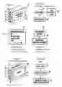
FIG. 1 is a perspective view of a digital picture frame, showing interior components systematically;
FIG. 2 is a flow chart of example logic for bezel illumination based on motion;
FIG. 3 is a screen shot of a user interface for enabling a user to select bezel illumination options;
FIG. 4 is a flow chart of example logic for bezel illumination based on ambient light level;
FIG. 5 is a perspective view of an electronics device, showing interior components systematically; and
FIG. 6 is a flow chart of example logic for establishing bezel illumination color to match room color based on colorimetry from a camera.
DETAILED DESCRIPTION OF THE PREFERRED EMBODIMENT
Referring initially to FIG. 1, a digital photo frame assembly 10 includes a display 12 and bezel 14 framing the display 12. The display 12 may be an LCD display or any other mode of display screen, and it may be a touch screen display. The bezel 14 may be comprised of plastic; however it is not limited to a plastic medium.
Plural light sources 16 such as light emitting diodes (LED) may be disposed inside the bezel 14 as shown to illuminate it in accordance with principles discussed below under control of a processor 18. The processor 18 accesses a computer readable medium 20 such as solid state or disk-based storage and bearing digital photographs and software code executable by the processor 18. Under control of user input from an input device such as, e.g., the touch screen display, the processor can present a still digital image from the storage medium 20 on the display 12.
A motion sensor 22 and/or an ambient light sensor 24 may also be provided in the assembly 10 and may communicate with the processor 20. The motion sensor 22 generates signals representative of the motion of objects such as humans in front of the assembly 10. The ambient light sensor 24 generates signals representative of the level of ambient light in the space in which the assembly 10 is disposed.
FIG. 2 shows how the illumination of the bezel 14 may be established in response to motion in the room in which the assembly 10 is disposed. If motion above a threshold is detected at decision diamond 26, the processor at block 28 may dim the illumination provided by the light sources 16 by, e.g., reducing the voltage sent to the light sources 16. Or, the processor may extinguish illumination of the bezel altogether when motion is sensed by deenergizing the light sources 16.
On the other hand, when no motion above the threshold has been sensed, e.g., for longer than a threshold period, the logic may move to block 30 to illuminate the bezel by energizing deenergized light sources 16 or by increasing the voltage to those light sources 16 that are already energized.
It is to be understood that the opposite logic may be used, i.e., when motion not is sensed the illumination of the bezel may be reduced or terminated and when motion is sensed the bezel may be illuminated. In other words, the “yes” and “no” branches from decision diamond 26 in FIG. 2 may be reversed in alternate embodiments.
Additionally, if desired the user may be given the option of selecting illumination features. FIG. 3 shows a user interface 34 that the processor 18 may cause to be presented on the display 12, in which the user can command the processor to, e.g., dim the light sources 16 when motion is sensed, turn the light sources on when motion is sensed, or turn the light sources off when motion is sensed. Furthermore, when, for example, the light sources 16 are composed of color LEDs of differing colors (e.g., red, green, and blue), the user may be given the option of selecting the desired color of illumination of the bezel. In response, if the user selects “red”, only red light sources 16 are energized during the logic of FIG. 2. It is to be understood that the user interface of FIG. 3 may be used in any of the embodiments discussed herein the permit a user to define the color of the light used to illuminate the various bezels.
In addition to or in lieu of using motion to establish bezel illumination, ambient light levels surrounding the assembly 10 as sensed by the light sensor 24 may be used. Turning to FIG. 4, ambient light level is detected by the light sensor 24 at block 36 and sent to the processor 18. In response to the ambient light level, at block 38 the processor 18 establishes the illumination of the bezel 14 accordingly. For example, brighter ambient light can result in increased voltage being sent to the light sources 16, whereas dimmer ambient light can result in decreased voltage being sent to the light sources 16. Or, the opposite paradigm may be used, e.g., brighter ambient light can result in decreased voltage being sent to the light sources 16, whereas dimmer ambient light can result in increased voltage being sent to the light sources 16.
It is to be understood that the processor 18 may gradually (over the interval of several seconds) brighten illumination, i.e., may gradually increase the voltage to the light sources 16, when it determines based on either motion or ambient that bezel illumination should be increased, to avoid sudden brightness being inflicted on a viewer who might have just awakened.
FIG. 5 shows an alternate embodiment. A consumer electronics (CE) device 40 includes a housing 42 holding a video display 44 such as a flat panel display. A processor 46 is in the housing 42 and accesses a computer readable medium 48 to execute logic below. The CE device 40 may be, without limitation, a digital camera, camcorder, telephone, personal digital assistant (PDA), or TV, in which latter case the device 40 typically includes a TV tuner 50.
A camera 52 is supported in or on the housing 42 as shown. The camera 52 sends signals to the processor 46, which derives colorimetry information therefrom. Thus, the camera 52 can be positioned to image the room or space in which the device 40 is disposed, with the processor 46 using signals from the camera to determine colors/hues in the room or space.
As also shown, a bezel 54, which, like the other bezels herein, may be transparent or translucent, frames the display 44. Light sources 56 are disposed in or behind the bezel 54 and are energized under control of the processor 46 to internally illuminate the bezel 54. The light sources 56 can be LEDs of various colors.
With this in mind, the logic of FIG. 6 may now be appreciated. The camera 52 images the space or room in which the device 40 is disposed at block 58 and sends a signal representative thereof to the processor 48, which analyzes the image signal for color at block 60. At block 62 the processor 46 establishes, by energizing the appropriately colored light sources 56, the color of the illumination of the bezel 54. Alternatively to a camera image, the processor may analyze the colors in an image downloaded into the device 40 using, e.g., a removable memory medium.
In any case, the processor 46 may use heurisitics or a table lookup or other appropriate method to establish bezel illumination color based on an image color. As an example, the processor may establish the bezel illumination to be the same color as the predominant color, in terms of number of pixels for instance, in the image. Or, the processor may establish bezel illumination color to be a predetermined different color from the predominant image color, e.g., the processor may cause only blue light sources to be energized when the predominant color of the room is green. Yet again, the processor can execute a table lookup of bezel illumination color versus primary and secondary image colors. Or, the processor may simply present a color palette on the display showing the imaged color(s) and permit the user to select from the palette the color to be used in illuminating the bezel.
While the particular BEZEL ILLUMINATION FOR DIGITAL DEVICES is herein shown and described in detail, it is to be understood that the subject matter which is encompassed by the present invention is limited only by the claims.
Claims
What is claimed is:1. Digital photo frame assembly comprising:
frame;
display bordered by the frame;
at least one light source positioned to internally illuminate the frame;
computer readable storage medium bearing digital still images; and
processor causing at least one image from the medium to be presented on the display, the processor establishing an illumination of the frame based at least in part on a motion signal and/or an ambient light signal received by the processor.
2. The assembly of claim 1, wherein the frame is established by a bezel.
3. The assembly of claim 2, wherein the light source includes plural light emitting diodes (LED) juxtaposed with the bezel.
4. The assembly of claim 1, comprising a motion sensor communicating with the processor and sending a motion signal to the processor in response to motion of an object relative to the assembly, the processor establishing the illumination of the frame in response to the motion signal.
5. The assembly of claim 1, comprising a light sensor communicating with the processor and sending an ambient light signal to the processor representative of a level of ambient light external to the assembly, the processor establishing the illumination of the frame in response to the ambient light signal.
6. The assembly of claim 1, wherein the processor establishes at least three different illuminations of the frame in response to, respectively, three different motion signals and/or three different ambient light signals.
7. An electronic apparatus, comprising:
a video display;
a camera positioned to image a space in front of the display; and
a processor receiving signals from the camera and responsive thereto establishing a color of a user interface presented on the display, and/or a color of a bezel framing the display.
8. The apparatus of claim 7, wherein the apparatus includes a TV tuner.
9. The apparatus of claim 7, wherein the camera is mounted on a housing of the apparatus.
10. The apparatus of claim 7, wherein the processor uses colorimetry information from the camera to establish the color.
11. The apparatus of claim 7, wherein the processor establishes a color of a user interface in response to the signals from the camera.
12. The apparatus of claim 7, wherein the processor establishes a color of a bezel framing the display in response to the signals from the camera.
13. An electronic apparatus, comprising:
a video display;
a bezel framing the display;
plural light sources positioned to internally illuminate the bezel, at least a first light source being characterized by a first color and a second light source being characterized by a second color; and
a processor communicating with the light sources, the processor energizing the first light source but not the second light source in response to a first user-input bezel color selection signal representing the first color, the processor energizing the second light source but not the first light source in response to a second user-input bezel color selection signal representing the second color.
14. The apparatus of claim 13, comprising a TV tuner communicating with the processor.
15. The apparatus of claim 13, wherein the apparatus is embodied in a video camera.
16. The apparatus of claim 13, wherein the apparatus is embodied in a camcorder.
17. The apparatus of claim 13, wherein the apparatus is embodied in a telephone.
18. The apparatus of claim 13, wherein the apparatus is embodied in a personal digital assistant (PDA).
19. The apparatus of claim 13, wherein the light sources are light emitting diodes (LED) positioned inside the bezel.
Images & Drawings included:

Sources:
- United States Patent and Trademark Office - verify current appl. status at the USPTO↗
Recent applications in this class:
- » 20250008032 2025-01-02
INFORMATION PROCESSING SYSTEM, INFORMATION SYNCHRONIZATION SYSTEM, AND NON-TRANSITORY COMPUTER READABLE MEDIUM - » 20240163380 2024-05-16
Multi-function device communities for optimization of device image quality - » 20220217242 2022-07-07
Communication apparatus having power related predetermined processing, method of controlling the same, and storage medium - » 20210075922 2021-03-11
Information processing apparatus for enabling user access personal setting of another - » 20210021721 2021-01-21
Communication apparatus using an advertising signal, method of controlling the same, and storage medium - » 20200014806 2020-01-09
Communication apparatus having first or second state determination, method of controlling the same, and storage medium - » 20180167524 2018-06-14
Communication apparatus having specific state determination method of controlling the same, and storage medium - » 20170289367 2017-10-05
Viewing aid with tracking system, and method of use - » 20170195506 2017-07-06
IMAGE FORMING APPARATUS FORMING LOCATION FREE PRINT SYSTEM AND PRINT JOB RETRIEVAL METHOD BY THE SAME - » 20170094080 2017-03-30
Image processing apparatus and non-transitory computer readable medium for more uniformly distributing documents
Recent applications for this Assignee:
- » 20250280125 2025-09-04
IMAGE DATA ENCODING AND DECODING - » 20250199527 2025-06-19
INFORMATION PROCESSING DEVICE, INFORMATION PROCESSING METHOD, AND PROGRAM - » 20250175646 2025-05-29
IMAGE PROCESSING APPARATUS AND METHOD - » 20250150244 2025-05-08
INTERFACE CIRCUIT AND INFORMATION PROCESSING SYSTEM - » 20250126294 2025-04-17
IMAGE PROCESSING APPARATUS AND METHOD - » 20250123622 2025-04-17
INFORMATION PROCESSING APPARATUS, INFORMATION PROCESSING METHOD, AND PROGRAM - » 20250119802 2025-04-10
TERMINAL DEVICE AND METHOD - » 20250113080 2025-04-03
REPRODUCING DEVICE, REPRODUCING METHOD, PROGRAM, AND TRANSMITTING DEVICE - » 20250068301 2025-02-27
INFORMATION PROCESSING APPARATUS FOR RESPONDING TO FINGER AND HAND OPERATION INPUTS - » 20250044935 2025-02-06
INFORMATION PROCESSING DEVICE, INFORMATION PROCESSING METHOD, AND PROGRAM