Device for displaying a plurality of detectable variable quantities
US20110050408A1
2011-03-03
12/713,521
2010-02-26
✅ Patent granted
US 8,314,693 B2
2012-11-20
-
-
Daniel Wu | Kam Ma
2031-04-26
Abstract:
A device for displaying a plurality of detectable variable quantities of a motor vehicle that are in a ratio to one another, each quantity represented by a band, and the bands being arranged relative to one another such that they form a variable geometric figure. The bands have a variable length depending on the deviation from an optimum ratio of the quantities to one another, and intersect in an intersection area.
Inventors:
- Stephan CIELER 12 🇩🇪 Frankfurt, Germany
- Katrin LÜBBERT 2 🇩🇪 Darmstadt, Germany
- Guido Meier-Arendt 17 🇩🇪 Langen, Germany
- Carmen Solterbeck 2 🇩🇪 Frankfurt, Germany
- Katrin Lübbert 1 🇩🇪 Darmstadt, Germany
Assignee:
- CONTINENTAL AUTOMOTIVE GMBH 2,462 🇩🇪 Hannover, Germany
- Continental GmbH 1 🇩🇪 Hannover, Germany
Interested in similar patents?
Get notified when new applications in this technology area are published.
Classification:
B60Q1/00 IPC
Arrangement of optical signalling or lighting devices, the mounting or supporting thereof or circuits therefor
B60K35/00 » CPC main
Arrangement of adaptations of instruments specially for vehicles; Dashboards
B60K35/00 » CPC main
Arrangement of adaptations of instruments
B60K2370/155 » CPC further
Details of arrangements or adaptations of instruments specially adapted for vehicles, not covered by groups; Output devices or features thereof Virtual instruments
B60Q1/50 IPC
Arrangement of optical signalling or lighting devices, the mounting or supporting thereof or circuits therefor the devices being primarily intended to indicate the vehicle, or parts thereof, or to give signals, to other traffic for indicating other intentions or conditions, e.g. request for waiting or overtaking
G09F9/00 IPC
Indicating arrangements for variable information in which the information is built-up on a support by selection or combination of individual elements
Description
BACKGROUND OF THE INVENTION
1. Field of the Invention
The invention relates to a device for displaying a plurality of detectable variable quantities of a motor vehicle that are in a ratio to one another, it being possible for each quantity to be represented by a band, the bands being arranged relative to one another in such a way that they form a variable geometric figure.
2. Description of the Related Art
It is known in the case of such a display device to represent a plurality of mutually independent displays of a plurality of detectable variable quantities by light bands that consist of individual drivable light cells. Here, the light bands are arranged relative to one another such that driven light cells of values that can theoretically be assigned to one another form to a specific geometric figure.
In this case, the quantities can be quantities specific to motor vehicles such as driving speed and/or engine speed and/or instantaneous average fuel consumption.
If the displays of these three quantities are such that the specific geometric figure lights up, it can thereby be indicated that a driving mode with optimum operating conditions is obtained with regard to fuel consumption.
The arrangement of the three displays next to one another requires a large amount of space.
SUMMARY OF THE INVENTION
It is an object of the invention to provide a display device of that conveys to an observer information that can be easily and quickly detected in conjunction with a low space requirement.
According to one embodiment of the invention by virtue of the fact that the bands each have a variable length depending on the deviation from an optimum ratio of the quantities to one another, and intersect in an intersection area.
It is thereby possible for an observer easily to detect whether the detected quantities are at a specific ratio to one another and, if not, which of the quantities deviates how sharply from the optimum and should be corrected.
In this case, the bands either can have the least length given an optimum ratio of the variable quantities to one another, or have the greatest length given an optimum ratio of the variable quantities to one another.
A symmetrical representation is obtained when the bands intersect in the middle.
The bands can have different contours. The bands can have, for example, a rectangular contour or an elliptical one.
Provide the observer information relating to an ecologically favorable driving mode, the variable quantities can be the instantaneous driving speed and/or the instantaneous engine speed and the instantaneous speed of the transmission of the motor vehicle.
The detectability of the individual quantities by the observer can be raised by virtue of the fact that the bands are of different color, the informativeness for the observer being further improved when the color or the color intensity of the bands varies depending on the respective length of the bands.
In a simple way, the bands can be represented by an optoelectronic display.
When the bands are light bands, this leads to a clearer detectability.
To provide the observer information relating to the longer-term driving behavior, a further display can be used to display the time or the kilometers traveled in the driving mode given an optimum and/or non-optimum ratio of the quantities to one another.
To this end, the time or the kilometers traveled during the optimum and/or non-optimum ratio of the quantities to one another can be represented by a bar graph.
Another possibility consists in that the time or the kilometers traveled during the optimum and/or non-optimum ratio of the quantities to one another can be represented in numerical values.
Other objects and features of the present invention will become apparent from the following detailed description considered in conjunction with the accompanying drawings. It is to be understood, however, that the drawings are designed solely for purposes of illustration and not as a definition of the limits of the invention, for which reference should be made to the appended claims. It should be further understood that the drawings are not necessarily drawn to scale and that, unless otherwise indicated, they are merely intended to conceptually illustrate the structures and procedures described herein.
BRIEF DESCRIPTION OF THE DRAWINGS
Exemplary embodiments of the invention is illustrated in the drawings and described in more detail below. In the drawings,
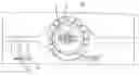
FIG. 1 is a device with a representation relating to high speed;
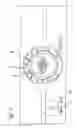
FIG. 2 is the device according to FIG. 1 with representation of an optimum ratio of the speed to the instantaneous gear selection; and
FIG. 3 is the device according to FIG. 1 with representation of suboptimum speed and gear selection.
DETAILED DESCRIPTION OF THE PRESENTLY PREFERRED EMBODIMENTS
The figures depict a display panel of a motor vehicle with a circular speed scale 1.
The speed scale 1 surrounds a device for displaying the speed and the gear selection, which comprises two light bands 2 and 3 intersecting at right angles in the middle.
In this case, the horizontal light band 2 can represent the speed information, and the light band 3 the gear selection information.
The light bands 2 and 3 have an elliptical type contour.
The representation of the two light bands 2 and 3 can vary as to their length.
The less the length of a light band 2 and 3, the more optimum is this quantity for an ecological driving mode.
Thus, a long light band 2 and short light band 3 of FIG. 1 shows that the speed of the motor vehicle is too high at the moment for the selected gear.
FIG. 2, in which both the light band 2 and the light band 3 have the least length, indicates that the instantaneous speed is at an optimum ratio to the selected gear of the motor vehicle transmission.
In turn, the two long light bands 2 and 3 FIG. 3 indicate that both the speed and the selected gear are suboptimum.
To the left next to the speed scale 1 is a first bar graph display 4 and a second bar graph display 5.
The first bar graph display 4 preferably represents a summed time during which the motor vehicle is operated in conjunction with an optimum ratio of speed and gear selection to one another.
The bar graph display 5 preferably indicates a summed time during which the motor vehicle is operated given an optimum ratio of speed and gear selection. In display 5, a time during which no such optimum driving mode takes place have been subtracted.
Thus, while there have shown and described and pointed out fundamental novel features of the invention as applied to a preferred embodiment thereof, it will be understood that various omissions and substitutions and changes in the form and details of the devices illustrated, and in their operation, may be made by those skilled in the art without departing from the spirit of the invention. For example, it is expressly intended that all combinations of those elements and/or method steps which perform substantially the same function in substantially the same way to achieve the same results are within the scope of the invention. Moreover, it should be recognized that structures and/or elements and/or method steps shown and/or described in connection with any disclosed form or embodiment of the invention may be incorporated in any other disclosed or described or suggested form or embodiment as a general matter of design choice. It is the intention, therefore, to be limited only as indicated by the scope of the claims appended hereto.
Claims
We claim:1. A display device configured to display a plurality of detectable variable quantities of a motor vehicle that are in a ratio to one another, the display comprising:
a first band configured to display a first value of a first variable, the first band having a variable length; and
a second band configured to display a second value of a second variable, the second band having a variable length,
the first and second bands arranged relative to one another to intersect in an intersection area to form a variable geometric figure,
wherein the lengths of the first and second bands are based at least in part on a deviation from an optimum ratio of the first value of the first variable to the second value of the second variable.
2. The display device as claimed in claim 1, wherein the first and second bands have a least length given an optimum ratio of the variable quantities to one another.
3. The display device as claimed in claim 1, wherein the first and second bands have a greatest length given an optimum ratio of the variable quantities to one another.
4. The display device as claimed in claim 1, wherein the first and second bands intersect at respective middle portions of the first and second bands.
5. The display device as claimed in claim 1, wherein each of the first and second bands have a rectangular contour.
6. The display device as claimed in claim 1, wherein each of the first and second bands have an elliptical contour.
7. The display device as claimed in claim 1, wherein the variable quantities are selected from the group consisting of instantaneous driving speed, instantaneous engine speed, instantaneous speed of a transmission, and instantaneous fuel consumption.
8. The display device as claimed in claim 1, wherein the first and second bands are of different color.
9. The display device as claimed in claim 8, wherein one of the color and a color intensity of the first and second bands varies based at least in part on respective lengths of the first and second bands.
10. The display device as claimed in claim 1, wherein the first and second bands are produced by an optoelectronic display.
11. The display device as claimed in claim 1, wherein the first and second bands are light bands.
12. The display device as claimed in claim 1, further comprising a further display configured to display at least one of a time and kilometers traveled in a driving mode based on one of an optimum and a non-optimum ratio of the values of the first and second bands to one another.
13. The display device as claimed in claim 12, wherein the at least one of the time or the kilometers traveled are represented by a bar graph.
14. The device as claimed in claim 12, wherein the at least one of the time and the kilometers traveled are represented by numerical values.
15. The display device as claimed in claim 9, wherein the first and second bands are produced by an optoelectronic display.
16. The display device as claimed in claim 15, wherein the first and second bands are light bands.
17. The display device as claimed in claim 1, wherein the first and second bands are arranged to extend substantially perpendicular to each other.
Images & Drawings included:


Sources:
- United States Patent and Trademark Office - verify current appl. status at the USPTO↗
Recent applications in this class:
- » 20250276576 2025-09-04
VEHICLE ENTERTAINMENT APPARATUS - » 20250262931 2025-08-21
VEHICLE DISPLAY APPARATUS - » 20250262930 2025-08-21
DISPLAY CONTROL DEVICE FOR A VEHICLE, DISPLAY SYSTEM FOR A VEHICLE, DISPLAY CONTROL METHOD FOR A VEHICLE, AND PROGRAM - » 20250236174 2025-07-24
Interactive Safety System for Vehicles - » 20250222767 2025-07-10
INFORMATION DISPLAY SYSTEM AND VEHICLE INFORMATION DISPLAY SYSTEM USING THE SAME - » 20250222766 2025-07-10
CRUISE CONTROL USER INTERFACES - » 20250222765 2025-07-10
DISPLAY DEVICE AND DISPLAY METHOD - » 20250196634 2025-06-19
VEHICLE INPUT DEVICE, VEHICLE INPUT METHOD, AND NON-TRANSITORY STORAGE MEDIUM STORED WITH VEHICLE INPUT PROGRAM - » 20250162412 2025-05-22
VEHICLE OVERHEAD CONSOLE BRACKET - » 20250145001 2025-05-08
PRESENTATION CONTROL DEVICE AND NON-TRANSITORY COMPUTER READABLE STORAGE MEDIUM
Recent applications for this Assignee:
- » 20250006057 2025-01-02
VEHICLE-EXIT ASSIST APPARATUS - » 20240312120 2024-09-19
METHOD AND DEVICE FOR PROVIDING A VISUALIZATION OF A VEHICLE, AND VEHICLE - » 20240295913 2024-09-05
ELECTRONIC DEVICE AND METHOD OF RESPONDING TO A TRIGGER TO WAKE UP - » 20240126118 2024-04-18
Display system and method for operating a display system - » 20240103589 2024-03-28
Frame for an electro-optical display and electro-optical display having a frame - » 20240103348 2024-03-28
Device for securing an optical device - » 20240103153 2024-03-28
Distance measuring system - » 20240100956 2024-03-28
Control unit circuit for a motor vehicle, motor vehicle and operating method for the control unit circuit - » 20240053161 2024-02-15
Method for predicting a velocity profile of a vehicle - » 20230356682 2023-11-09
Method for adapting a triggering algorithm of a personal restraint device and control device for adapting a triggering algorithm of a personal restaint device