Apparatus for mounting device having electrical terminals
US20110085295A1
2011-04-14
12/750,912
2010-03-31
✅ Patent granted
US 8,289,695 B2
2012-10-16
-
-
Adrian S Wilson
2030-10-16
Abstract:
An apparatus for mounting a device having electrical terminals includes a bracket and a tray. The bracket has two first protruding portions and two pivoting mechanisms adapted to be connected to a base. The tray is positioned between the bracket and the base and adapted to carry the device having electrical terminals. The tray has a bottom surface and two first protrusions. When the bracket is pivotally connected to the base and when the bracket is rotated so that the first protruding portions slide on the first protrusions, the first protrusions are pushed to move toward the pivoting mechanisms and drive the bottom surface to move.
Assignee:
- HANNSTAR DISPLAY CORP. 24 🇹🇼 Taipei County, Taiwan
Interested in similar patents?
Get notified when new applications in this technology area are published.
Classification:
G06F1/16 IPC
Details not covered by groups - and Constructional details or arrangements
G06F1/187 » CPC main
Details not covered by groups - and; Constructional details or arrangements; Packaging or power distribution; Internal mounting support structures, e.g. for printed circuit boards, internal connecting means Mounting of fixed and removable disk drives
G06F1/1658 » CPC further
Details not covered by groups - and; Constructional details or arrangements for portable computers; Constructional details or arrangements of portable computers not specific to the type of enclosures covered by groups - ; Details related to functional adaptations of the enclosure, e.g. to provide protection against EMI, shock, water, or to host detachable peripherals like a mouse or removable expansions units like PCMCIA cards, or to provide access to internal components for maintenance or to removable storage supports like CDs or DVDs, or to mechanically mount accessories related to the mounting of internal components, e.g. disc drive or any other functional module
H05K7/18 IPC
Constructional details common to different types of electric apparatus Construction of rack or frame
H05K7/18 IPC
Constructional details common to different types of electric apparatus Construction of rack or frame
H02B1/48 IPC
Frameworks, boards, panels, desks, casings; Details of substations or switching arrangements; Casings; Parts thereof or accessories therefor; Boxes; Parts thereof or accessories therefor Mounting of devices therein
H05K5/00 IPC
Casings, cabinets or drawers for electric apparatus
H05K5/00 IPC
Casings, cabinets or drawers for electric apparatus
H05K7/00 IPC
Constructional details common to different types of electric apparatus
H05K7/00 IPC
Constructional details common to different types of electric apparatus
Description
CROSS REFERENCE TO RELATED APPLICATION
This application claims the priority benefit of Taiwan Patent Application Serial Number 098218816 filed Oct. 13, 2009, the full disclosure of which is incorporated herein by reference.
BACKGROUND OF THE INVENTION
1. Field of the Invention
The invention relates to a mounting apparatus, and more particularly, to an apparatus for mounting a device having electrical terminals.
2. Description of the Related Art
In general, a hard disk is installed in a computer and has a size of 5.25, 3.5 or 2.5 inches. The 5.25-inch and 3.5-inch hard disks are commonly installed in desktop computers while 2.5-inch hard disks are usually installed in laptop computers.
In comparison with desktop computers, the connectors in a laptop computer for a hard disk are usually fixed because the available room in the computer is very small. Therefore, when a user desires to install a hard disk in a laptop computer, it is required to push the hard disk toward the fixed connectors in order to couple with each other. A pull at the hard disk can then separate it from the fixed connectors.
However, the fixed connectors are usually tightly coupled to the electrical terminals of the hard disk when the hard disk is electrically connected to the fixed connectors. Therefore, it is hard to separate the hard disk from the fixed connectors. To demount the hard disk from the computer, a large pull force is required to be exerted at the hard disk. This may cause the hard disk to collide with parts in the computer and therefore damage them when the pull force is not under control after the hard disk has been pulled out.
Accordingly, there exists a need to provide an apparatus for mounting a hard disk to solve the above-mentioned problems.
SUMMARY OF THE INVENTION
The present invention provides an apparatus for mounting a device having electrical terminals. The apparatus of the present invention can solve the prior art problem that a hard disk will collides with parts in the computer when the pull force does not stop after the hard disk has been pulled out.
In one embodiment, the apparatus of the present invention includes a bracket and a tray. The bracket has two opposing longitudinal side surfaces, two first protruding portions and two pivoting mechanisms. The first protruding portions are connected to the longitudinal side surfaces respectively. The pivoting mechanisms are connected to the longitudinal side surfaces of the bracket respectively and adapted to be connected to two longitudinal side surfaces of a base. The tray is positioned between the bracket and the base and adapted to carry a device having electrical terminals. The tray has a bottom surface and two first protrusions. The bottom surface has two opposing longitudinal side surfaces. The first protrusions are connected to the longitudinal side surfaces of the tray and positioned corresponding to the first protruding portions, respectively. When the bracket is pivotally connected to the longitudinal side surfaces of the base and when the bracket is pivotally rotated to let the first protruding portions slide on the first protrusions, the first protrusions are pushed to move toward the pivoting mechanisms and drives the bottom surface to move.
The foregoing, as well as additional objects, features and advantages of the invention will be more readily apparent from the following detailed description, which proceeds with reference to the accompanying drawings.
BRIEF DESCRIPTION OF THE DRAWINGS
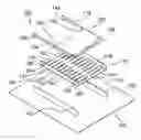
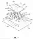
FIG. 1 is an exploded view of the apparatus for mounting a device having electrical terminals according to the present invention.
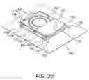
FIGS. 2a to 2c show the method of using the apparatus of the present invention to couple the carried device with an external electrical connector.
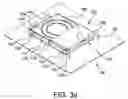
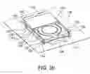
FIGS. 3a to 3b show the method of using the apparatus of the present invention to separate the carried device from the external electrical connector.
DETAILED DESCRIPTION OF THE PREFERRED EMBODIMENT
Referring to FIG. 1, the apparatus 100 for mounting a device having electrical terminals according to the present invention includes a tray 110 configured to carry a device having electrical terminals. The tray 110 has a bottom surface 112 and two opposing longitudinal side surfaces 116 extending upward from two opposing longitudinal sides 114 of the bottom surface 112, respectively. Therefore, the tray 110 is generally U-shaped. Protrusions 122, 124 are positioned on the two opposing longitudinal side surfaces 116 and adjacent to the bottom surface 112, wherein the protrusions 122 are adjacent to one transverse side 117 of the bottom surface 112 and the protrusions 124 are adjacent to the other transverse side 118 of the bottom surface 112. Each of the protrusions 122, 124 has an inclined arc plane 126 and these planes 126 are inclined down toward the neighboring transverse sides 117 or 118.
In addition, the apparatus 100 further includes a plastic bracket 130 that is pivotally connected to two longitudinal side surfaces 192 of a base 190 in a computer through pivoting mechanisms 132 on two longitudinal side surfaces 134 thereof. In the present invention, the base 190 can be a circuit board or the housing of the computer. The bracket 130 further has hooked protruding portions 142, 144 that are positioned on the two longitudinal side surfaces 134 and opposite to each other across the pivoting mechanisms 132. Moreover, the protruding portions 142, 144 are also positioned corresponding to the protrusions 122 and 124 on the tray 110, respectively.
Referring to FIGS. 2a to 2c, when desiring to begin mounting a device having electrical terminals, such as a hard disk 180, the hard disk 180 is first fixed on the bottom surface 112 of the tray 110 by threading or hooking method with the electrical terminals thereof facing the rear end of the bracket 130. Afterward, a user can lift a handle 138 on the front end of the bracket 130 to move the protruding portions 142 upward. The tray 110, together with the hard disk 180 is placed under the bracket 130 and then pushed toward the rear end of the bracket 130 (see FIG. 2a). Subsequently, the handle 138 is pushed down the bracket 130 will therefore pivot clockwise. When the handle 138 is continued to be pushed down, the protruding portions 142 of the bracket 130 will be in contact with and slide downward along the inclined planes 126 of the protrusions 122. Since the inclined planes 126 of the protrusions 122 are inclined down toward the transverse side 117, the protruding portions 142 will push the protrusions 122 to move backward and toward the pivoting mechanisms 132. Consequently, the tray 110 will be driven to move backward accordingly. In this meantime the protruding portions 144 on the rear end of the tray 110 will move upward. Since the tray 110 is pushed to move backward, the protruding portions 144 will slide upward along the inclined planes 126 of the protrusions 124 (see FIG. 2b). When the handle 138 is continued to be pushed down, the protruding portions 142 will slide down to the lower end of the inclined planes 126 of the protrusions 122 and the protruding portions 144 will slide up to the upper end of the inclined planes 126 of the protrusions 124. At this moment the tray 110 will be pushed to be in position (see FIG. 2c).
During the backward movement of the tray 110, the electrical terminals of the hard disk 180 will gradually move toward the corresponding electrical connector 194 in rear of the tray 110. When the tray 110 is moved to be in position, the electrical terminals of the hard disk 180 will be coupled with the corresponding electrical connector 194 so that the hard disk 180 is electrically connected to the computer.
Referring to FIGS. 3a to 3b, when desiring to demount the hard disk 180 from the computer, a user can lift the handle 138 to let the bracket 130 pivoted counterclockwise. At this moment the protruding portions 144 on the rear end of the tray 110 will slide downward along the inclined planes 126 of the protrusions 124 to push the protrusions 124 to move forward and toward the pivoting mechanisms 132. In this way the tray 110 will be driven to move forward to pull the electrical terminals of the hard disk 180 out of the electrical connector 194 (see FIG. 3a). When the handle 138 is continued to be pulled up, the protruding portions 144 will continuously exert a forward force on the tray 110. Finally, the hard disk 180 will be completely separated from the electrical connector 194 (see FIG. 3b).
According to the apparatus of the present invention, a user can mount or demount a hard disk by simply rotating the handle on the bracket. There is no any need to use a screwdriver. Most importantly, the apparatus of the present invention can solve the prior art problem that a hard disk will collide with parts in the computer when the pull force is not under control after the hard disk has been pulled out.
It should be appreciated that although the device having electrical terminals described in the embodiments of the present invention is a hard disk, the apparatus of the present invention can also be used to mount other devices, such as a CD-ROM drive or simply an electrical connector.
Although the preferred embodiments of the invention have been disclosed for illustrative purposes, those skilled in the art will appreciate that various modifications, additions and substitutions are possible, without departing from the scope and spirit of the invention as disclosed in the accompanying claims.
Claims
What is claimed is:1. An apparatus for mounting a device having electrical terminals, comprising:
a bracket having two opposing longitudinal side surfaces, two first protruding portions and two pivoting mechanisms, the first protruding portions being connected to the longitudinal side surfaces respectively, the pivoting mechanisms being connected to the longitudinal side surfaces of the bracket respectively and adapted to be connected to two longitudinal side surfaces of a base; and
a tray positioned between the bracket and the base, adapted to carry a device having electrical terminals, the tray having a bottom surface and two first protrusions, the bottom surface having two opposing longitudinal side surfaces, the first protrusions being connected to the longitudinal side surfaces of the tray and positioned corresponding to the first protruding portions, respectively,
wherein when the bracket is pivotally connected to the longitudinal side surfaces of the base and when the bracket is pivotally rotated to let the first protruding portions slide on the first protrusions, the first protrusions are pushed to move toward the pivoting mechanisms and drives the bottom surface to move.
2. The apparatus as claimed in claim 1, wherein each the first protrusion has an inclined plane, the first protruding portions slide downward along the inclined planes of the first protrusions, respectively.
3. The apparatus as claimed in claim 2, wherein the inclined planes of the first protrusions are arc planes.
4. The apparatus as claimed in claim 1, wherein the bracket further has a handle.
5. The apparatus as claimed in claim 1, wherein the bracket further has two second protruding portions connected to the longitudinal side surfaces of the bracket respectively and positioned opposite to the first protruding portions across the pivoting mechanisms, the tray further has two second protrusions connected to the longitudinal side surfaces thereof and positioned corresponding to the second protruding portions respectively, wherein when the bracket is pivotally connected to the longitudinal side surfaces of the base and when the bracket is pivotally rotated to let the second protruding portions slide on the second protrusions, the second protrusions are pushed to move toward the pivoting mechanisms and drives the bottom surface to move.
6. The apparatus as claimed in claim 5, wherein each the second protrusion has an inclined plane, the second protruding portions slide downward along the inclined planes of the second protrusions, respectively.
7. The apparatus as claimed in claim 6, wherein the inclined planes of the second protrusions are arc planes.
8. The apparatus as claimed in claim 5, wherein the device having electrical terminals is a hard disk.
9. The apparatus as claimed in claim 5, wherein the device having electrical terminals is a CD-ROM drive.
10. The apparatus as claimed in claim 5, wherein the base is a circuit board.
11. The apparatus as claimed in claim 5, wherein the base is a housing of a computer.
Images & Drawings included:


Sources:
- United States Patent and Trademark Office - verify current appl. status at the USPTO↗
Recent applications in this class:
- » 20250181123 2025-06-05
COMPUTER CHASSIS - » 20250138604 2025-05-01
HOT SWAPPABLE DRIVE CAGE - » 20250021142 2025-01-16
FIXING BRACKET FOR FACILITATING ASSEMBLY AND DISASSEMBLY OF HARD DISK IN ELECTRONIC DEVICES - » 20250021141 2025-01-16
Mounting System for Storage Drive - » 20240411349 2024-12-12
MOUNT BRACKET, STORAGE DEVICE ASSEMBLY, AND SERVER - » 20240302877 2024-09-12
QUICK RELEASE MECHANISM AND ELECTRONIC ASSEMBLY - » 20240295908 2024-09-05
Transverse drive tray assembly - » 20240288915 2024-08-29
DRIVE ADAPTOR FOR A DRIVE CARRIER - » 20240264645 2024-08-08
INTEGRATED LOCKING MECHANISM FOR DRIVE BLANKS - » 20240256010 2024-08-01
FIXING FRAME FOR COMPUTER APPARATUS
Recent applications for this Assignee:
- » 20120264260 2012-10-18
Method for manufacturing thin film transistor (TFT) array substrate - » 20120256899 2012-10-11
Gate driving circuit receiving a plurality of clock signals and having forward and reverse driving modes and driving method thereof - » 20120000702 2012-01-05
Two-side cable-arrangement structure and electronic apparatus therewith - » 20110304793 2011-12-15
Liquid crystal display panel having a touch function - » 20110267766 2011-11-03
Position-shifting structure - » 20110157520 2011-06-30
Liquid crystal display and fabrication method thereof - » 20110102366 2011-05-05
Projective capacitive touch sensor - » 20110075443 2011-03-31
LIGHT EMITTING UNIT, BACKLIGHT MODULE AND DISPLAY DEVICE - » 20110069430 2011-03-24
Connector for mounting a flexible printed circuit board - » 20110063535 2011-03-17
Pixel structure of liquid crystal display panel