LED LAMP RADIATOR
US20110253355A1
2011-10-20
12/763,459
2010-04-20
Abstract:
An LED lamp radiator comprising a generally ring-shaped upper base member; a generally ring-shaped lower base member; a plurality of fins fixedly attached to the upper base member and the lower base member, forming a generally cylindrical shape. Each of the plurality of fins having an upper portion, a middle portion and a lower portion, the upper portion being fixedly attached to a periphery of the upper base member, the lower portion being fixedly attached to a periphery of the lower base member, and the middle portion being configured for physically separating the upper base member and the lower base member. The LED lamp radiator further comprising a support plate removably secured to the upper base member, the support plate configured for supporting an LED lamp within the generally cylindrical shape formed by the upper base member, the lower base member and the plurality of fins.
Inventors:
- Wenming He 1 🇨🇳 Putian City, China
- Chunsheng Tang 1 🇨🇳 Putian City, China
- Bin Xu 1 🇨🇳 Putian City, China
Assignee:
- FUJIAN ZHONGKE WANBANG PHOTOELECTRIC CO. LTD. 1 🇨🇳 Putian City, China
Interested in similar patents?
Get notified when new applications in this technology area are published.
Classification:
F21V29/83 » CPC main
Protecting lighting devices from thermal damage; Cooling or heating arrangements specially adapted for lighting devices or systems; Cooling arrangements characterised by passive heat-dissipating elements, e.g. heat-sinks the elements having apertures, ducts or channels, e.g. heat radiation holes
F21V29/773 » CPC further
Protecting lighting devices from thermal damage; Cooling or heating arrangements specially adapted for lighting devices or systems; Cooling arrangements characterised by passive heat-dissipating elements, e.g. heat-sinks with fins or blades with essentially identical diverging planar fins or blades, e.g. with fan-like or star-like cross-section the planes containing the fins or blades having the direction of the light emitting axis
F21V19/0055 » CPC further
Fastening of light sources or lamp holders the light sources being semiconductors devices, e.g. LEDs; Fastening of light source holders, e.g. of circuit boards or substrates holding light sources by screwing
F21Y2115/10 » CPC further
Light-generating elements of semiconductor light sources Light-emitting diodes [LED]
F28F1/14 » CPC further
Tubular elements; Assemblies of tubular elements; Tubular elements and assemblies thereof with means for increasing heat-transfer area, e.g. with fins, with projections, with recesses the means being only outside the tubular element and extending longitudinally
F28F7/00 IPC
Elements not covered by group , or
Description
TECHNICAL FIELD
The present invention relates to the field of illumination devices and particularly to a radiator for an LED lamp.
BACKGROUND
A light-emitting diode (LED) is a semiconductor light source. LEDs may present many advantages (e.g., lower energy consumption and smaller size) over other light sources. LEDs may therefore be utilized as efficient light sources in fields such as automobiles, traffic lights, screen displays, general illumination, and the like. However, as the power of the LED increases, the amount of heat generated also increases. Heat generated in operation may cause the temperature of the LED to rise. The LED may burn out when the temperature exceeds a certain level.
SUMMARY
Accordingly, an embodiment of the present disclosure is directed to an LED lamp radiator. The LED lamp radiator may comprise a generally ring-shaped upper base member having a first outer diameter; a generally ring-shaped lower base member having a second outer diameter substantially identical to the first outer diameter; a plurality of fins fixedly attached to the upper base member and the lower base member, forming a generally cylindrical shape. Each of the plurality of fins has an upper portion, a middle portion and a lower portion, the upper portion being fixedly attached to a periphery of the upper base member, the lower portion being fixedly attached to a periphery of the lower base member, and the middle portion being configured for physically separating the upper base member and the lower base member. The LED lamp radiator may further comprise a support plate removably secured to the upper base member, the support plate configured for supporting an LED lamp within the generally cylindrical shape formed by the upper base member, the lower base member and the plurality of fins.
It is to be understood that both the foregoing general description and the following detailed description are exemplary and explanatory only and are not necessarily restrictive of the invention as claimed. The accompanying drawings, which are incorporated in and constitute a part of the specification, illustrate embodiments of the invention and together with the general description, serve to explain the principles of the invention.
BRIEF DESCRIPTION OF THE DRAWINGS
The numerous advantages of the present invention may be better understood by those skilled in the art by reference to the accompanying figures in which:
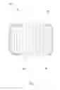
FIG. 1 is a side view of an LED lamp radiator;
FIG. 2 is an exploded view of the LED lamp radiator;
FIG. 3 is an isometric view of the LED lamp radiator;
FIG. 4 is a cross-sectional view of the LED lamp radiator;
FIG. 5 is a top view of the LED lamp radiator with a support plate installed; and
FIG. 6 is a bottom view of the LED lamp radiator with the support plate installed.
DETAILED DESCRIPTION
Reference will now be made in detail to the presently preferred embodiments of the invention, examples of which are illustrated in the accompanying drawings.
Heat generated during an operation of an LED may cause the temperature of the LED to rise. The LED may burn out when the temperature exceeds a certain level. Therefore, it may be appreciated to quickly transfer and/or emit the heat generated in order to improve the quality of illumination and service life of the LED.
Referring generally to FIGS. 1 through 6, a radiator 100 for an LED lamp is shown. It may be appreciated that, different from conventional radiators that distributes heat by conduction, the radiator 100 of the present disclosure improves the efficiency of the radiator by increasing airflow and enhancing heat dissipation performances. Furthermore, the radiator 100 of the present disclosure may also reduce material consumptions and/or per unit costs.
The radiator 100 comprises a generally ring-shaped upper base member 102, a generally ring-shaped lower base member 104 and a plurality of fins 106. The upper base member 102 may have a first outer diameter that is substantially identical to a second outer diameter of the lower base member 104. The fins 106 are fixedly attached to the upper base member and the lower base member, forming a generally cylindrical shape. In one embodiment, the plurality of fins 106 may be evenly spaced apart from each other. In addition, the plurality of fins 106 may be at least partially curved.
Each one of the plurality of fins 106 includes an upper portion 108, a middle portion 110 and a lower portion 112 (as illustrated in FIG. 4). The upper portion 108 of each fin 106 is fixedly attached to the periphery (e.g., outer edge surface) of the upper base member 102. Similarly, the lower portion 112 of each fin 106 is fixedly attached to the periphery (e.g., outer edge surface) of the lower base member 104. The middle portion 110 of each fin 106 has a predetermined length greater than zero, therefore providing a separation between the upper base member 102 and the lower base member 104.
The radiator 100 further comprises a support plate 114 for supporting an LED lamp within the radiator 100. For example, the support plate 114 may be configured for supporting the LED lamp within the generally cylindrical shape formed by the upper base member 102, the lower base member 104 and the plurality of fins 106. In one embodiment, the support plate 114 is a generally rectangular plate removably secured to the upper base member 102. The support plate 114 may include two screw holes 116 at which the LED lamp may be mounted to. It is understood that various other fastening means such as snap-fit clips, bolt joints, clamps and the like may be utilized without departing from the spirit and scope of the present disclosure. It is also understood that the upper base member 102 may have keyways 118 defined for receiving the support plate 114. It is also contemplated that the inner surface of the generally ring-shaped upper base member 102 may be threaded (as illustrated in FIGS. 2 through 4) to facilitate mounting of the radiator 100 to other devices.
It is believed that the present invention and many of its attendant advantages will be understood by the foregoing description. It is also believed that it will be apparent that various changes may be made in the form, construction and arrangement of the components thereof without departing from the scope and spirit of the invention or without sacrificing all of its material advantages. The form herein before described being merely an explanatory embodiment thereof, it is the intention of the following claims to encompass and include such changes.
Claims
What is claimed is:1. An LED lamp radiator, comprising:
a generally ring-shaped upper base member having a first outer diameter;
a generally ring-shaped lower base member having a second outer diameter substantially identical to the first outer diameter;
a plurality of fins fixedly attached to the upper base member and the lower base member, the plurality of fins, the upper base member and the lower base member forming a generally cylindrical shape, wherein each one of the plurality of fins having an upper portion, a middle portion and a lower portion, the upper portion being fixedly attached to a periphery of the upper base member, the lower portion being fixedly attached to a periphery of the lower base member, and the middle portion being configured for providing a separation between the upper base member and the lower base member; and
a support plate removably secured to the upper base member, the support plate configured for supporting an LED lamp within the generally cylindrical shape formed by the upper base member, the lower base member and the plurality of fins.
2. The LED lamp radiator of claim 1, wherein the plurality of fins are evenly spaced apart from each other.
3. The LED lamp radiator of claim 1, wherein the support plate is a generally rectangular plate having two screw holes.
4. The LED lamp radiator of claim 1, wherein the upper base member comprises a threaded inner surface.
Images & Drawings included:


Sources:
- United States Patent and Trademark Office - verify current appl. status at the USPTO↗
Similar patent applications:
- » 20150003082
LED LAMP RADIATING STRUCTURE - » 20150285485
Lamp radiator and LED energy saving lamp - » 20130249374
Passive phase change radiators for LED lamps and fixtures - » 20190203921
LED filament lamp using infrared radiation heat dissipation and LED lighting bar thereof - » 20100301724
LED lamp having heat radiating housing - » 20200158295
LED lamp with graphene radiator - » 20110156587
Radiating device for lamp and LED lamp - » 20180209592
GENERAL PURPOSE LED LAMP WITH MOLDED RADIATOR-CASE - » 20130277032
Connection structure of LED lamp holder and heat radiation fins - » 20070159828
Vertical LED lamp with a 360-degree radiation and a high cooling efficiency
Recent applications in this class:
- » 20250129926 2025-04-24
Lampshade Assembly and Snoot Tube Applying Same - » 20240384866 2024-11-21
Systems and methods for providing lighting using modular heat sink structures and lenses - » 20240377054 2024-11-14
DISPLAY DEVICE - » 20240219018 2024-07-04
Modular Lighting Apparatus with Cooling Channel - » 20240085012 2024-03-14
3D PRINTED INTEGRATED THERMAL MANAGEMENT AND LIGHT TRANSFER STRUCTURES - » 20240060636 2024-02-22
PHOSPHOR WHEEL - » 20240060635 2024-02-22
LED lamp with heat sink and with power supply received in housing - » 20240003530 2024-01-04
Light - » 20230392779 2023-12-07
HEATSINK, ACTIVE ENERGY IRRADIATION DEVICE, AND ACTIVE ENERGY IRRADIATION SYSTEM - » 20230042143 2023-02-09
ILLUMINATION SAFEGUARD ADAPTER FOR OUTSIDE WALL LIGHTING FIXTURES WITH BODY THAT EXTENDS BEYOND LIGHT BULB TO MAINTAIN LIGHT TRANSMISSION WHILE REDUCING VERTICAL LIGHT POLLUTION