Camshaft-grinding machine
US20120009851A1
2012-01-12
13/172,420
2011-06-29
✅ Patent granted
US 8,864,552 B2
2014-10-21
-
-
Lee D Wilson | Tyrone V Hall, Jr.
Andrew Wilford
2032-10-11
Abstract:
An apparatus for grinding a cam having an outer surface with outwardly convex and outwardly concave portions has a frame and a main drive on the frame for holding the cam and rotating it about a main axis. A pair of drive motors having respective output axes generally diametrally flank the main axis. Respective carriages carrying the drive motors are shiftable on the frame radially of the main axis. One of the motors is shiftable into an inner position in which the main axis extends through the one drive motor. Respective grinding wheels are rotatable by the motors about the respective axes, and the wheel of the one motor is of substantially smaller diameter than the wheel of the other motor.
Assignee:
- EMAG HOLDING GMBH 33 🇩🇪 Salach, Germany
Applicant:
Interested in similar patents?
Get notified when new applications in this technology area are published.
Classification:
B24B7/10 IPC
Machines or devices designed for grinding plane surfaces on work, including polishing plane glass surfaces; Accessories therefor Single-purpose machines or devices
B24B5/14 IPC
Machines or devices designed for grinding surfaces of revolution on work, including those which also grind adjacent plane surfaces; Accessories therefor involving centres or chucks for holding work for grinding conical surfaces, e.g. of centres
B24B19/125 » CPC main
Single-purpose machines or devices for particular grinding operations not covered by any other main group for grinding non-circular cross-sections, e.g. shafts of elliptical or polygonal cross-section for grinding cams or camshafts electrically controlled, e.g. numerically controlled
B24B5/42 IPC
Machines or devices designed for grinding surfaces of revolution on work, including those which also grind adjacent plane surfaces; Accessories therefor; Single-purpose machines or devices for grinding crankshafts or crankpins
B24B19/12 IPC
Single-purpose machines or devices for particular grinding operations not covered by any other main group for grinding non-circular cross-sections, e.g. shafts of elliptical or polygonal cross-section for grinding cams or camshafts
Description
FIELD OF THE INVENTION
The present invention relates to a camshaft grinding machine.
BACKGROUND OF THE INVENTION
It is known to make a so-called assembled camshaft by precision-machining a plurality of individual cams and then fixing them on a shaft. The disks can be made by sintering and are ground to the desired shape, which typically has a circularly annular body with coaxial inner and outer peripheries and a cam lobe projecting radially from the outer periphery at one location. Thus the outer surface of the cam is mostly outwardly convex except in concave regions where the cam lobe merges with the otherwise circular outer periphery of the cam.
It is known from GB 2,193,457 to clamp a stack of such cam disks coaxially on a mandrel so that they can all be machined at the same time. This represents a substantial gain in productivity.
In U.S. Pat. No. 5,392,566 a system is proposed for grinding such a stack of cams by first grinding all the outwardly convex surfaces using a large-diameter grinding wheel, then in a second operation with a different grinder the concave surfaces are ground with a small-diameter wheel. This produces a quality product, but the two-step grinding process increases production costs and time.
A tapered grinding disk is used in EP 0 991 497 that, with some complex control issues, is capable of producing a high-quality product. While the product is fairly good, it is necessary to use special-duty tools and grinders.
OBJECTS OF THE INVENTION
It is therefore an object of the present invention to provide an improved camshaft-grinding machine.
Another object is the provision of such an improved camshaft-grinding machine that overcomes the above-given disadvantages, in particular that allows cams to be ground in a fairly simple machine and with a high degree of accuracy.
SUMMARY OF THE INVENTION
An apparatus for grinding a cam having an outer surface with outwardly convex and outwardly concave portions has according to the invention a frame and a main drive on the frame for holding the cam and rotating it about a main axis. A pair of drive motors having respective output axes generally diametrally flank the main axis. Respective carriages carrying the drive motors are shiftable on the frame radially of the main axis. One of the motors is shiftable into an inner position in which the main axis extends through the one drive motor. Respective grinding wheels are rotatable by the motors about the respective axes, and the wheel of the one motor is of substantially smaller diameter than the wheel of the other motor.
With this system therefore the cam is engaged diametrally oppositely by the two grinding wheels, thereby eliminating the problem of deflecting the workpiece during machining. In addition since according to the invention the two wheels are between the two motors, it is possible to work with a small-diameter wheel that can get into the concavities of the cam while not having to deal with the complex control issues of a tapered grinding tool.
BRIEF DESCRIPTION OF THE DRAWING
The above and other objects, features, and advantages will become more readily apparent from the following description, reference being made to the accompanying drawing in which:
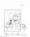
FIG. 1 is a schematic small-scale side view of the apparatus according to the invention;
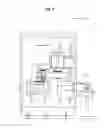
FIG. 2 is a large-scale bottom view of a detail of the apparatus; and
FIG. 3 is a section taken along plane III of FIG. 1.
DETAILED DESCRIPTION
As seen in FIG. 1 a grinder according to the invention has a stationary frame 1. Workpieces, here cams 2, are fixed on a shaft mandrel 19 that is fitted at its upper end into a chuck of a drive 3 for rotation about a vertical axis 8 and engaged at its lower end by a steady rest 15 having three arms 18 (FIG. 2) with rollers that are biased radially inward against the cylindrical outer surface of the mandrel shaft 19 to keep it centered on the axis 8. A grab 14 can pick mandrels 19 loaded with unmachined cams 2 off a conveyor 13 to load them into the machine and can take the machined cams out of the machine and place them on the conveyor 13 for movement to the next station.
According to the invention the frame 1 carries a first pair of vertical guide rails 9 and, horizontally offset therefrom, a second pair of vertical guide rails 9′. Respective vertically displaceable carriages 10 and 10′ are carried on these rails 9 and 9′ and in turn are provided with respective pairs of horizontal guide rails 11 and 11′. Respective horizontally shiftable carriages 12 and 12′ supporting respective grinders 4 and 4′ are carried on these rails 11 and 11′ and in turn support respective electric drive motors 6 and 6′ whose output shafts are centered on respective vertical axes 7 and 7′. These axes 7 and 7′ flank, are parallel to, and lie in a plane P with the axis 8. Thus both the drives 6 and 6′ can move horizontally in the X-direction and vertically in the Z-direction.
In accordance with the invention as shown in FIG. 3 the drive 6 carries a grinding wheel 5 with a large diameter 17 and the drive 6′ carries a grinding wheel 5′ with a small diameter 17′. In addition the drive 6 with the large wheel 5 is generally level with the headstock drive 3. Due to the large diameter 17 of the wheel 5, this is possible. On the other hand, the drive motor 6′ is located below the steady rest 15 and in fact overlaps the axis 8. Thus it is possible for its small-diameter wheel 5′ to engage the outer surface of the cams 2 even though the drive motor 6′ is of much greater diameter than the wheel 5′.
This setup has two significant advantages:
-
- 1. The use of grinding disks on opposite sides of the workpieces minimizes radial deflection and produces a more accurate product.
- 2. The use of one small-diameter disk and one large-diameter disk ensures fast grinding of the entire cam surface because the small disk can get into the concavities at the base of the cam lobe.
Claims
I claim:1. An apparatus for grinding a cam having an outer surface with outwardly convex and outwardly concave portions, the apparatus comprising:
a frame;
means on the frame for holding the cam and rotating it about a main axis;
a pair of drive motors having respective output axes generally diametrally flanking the main axis;
respective carriages carrying the drive motors and shiftable on the frame radially of the main axis, one of the motors being shiftable into an inner position in which the main axis extends through the one drive motor; and
respective grinding wheels rotatable by the motors about the respective axes, the wheel of the one motor being of substantially smaller diameter than the wheel of the other motor.
2. The grinding apparatus defined in claim 1 wherein the small-diameter wheel of the one motor has a smaller radius than a radius of curvature of the concave surface portion, and the wheel of the other motor has a larger radius than the radius of curvature of the concave surface portion.
3. The grinding apparatus defined in claim 1, wherein the means for holding and rotating the cam includes a motor and headstock and, spaced therefrom along the main axis, a steady rest.
4. The grinding apparatus defined in claim 3 wherein the steady rest is, relative to the main axis, between the wheel of the motor and the cam.
5. The grinding apparatus defined in claim 3 wherein the headstock lies between the motor of the means for holding ant the cam.
6. The grinding apparatus defined in claim 1, wherein the grinding disks are, relative to the main axis, axially between the drive motors.
7. The grinding apparatus defined in claim 1, further comprising
means for loading unmachined cams into the means for holding and for unloading machined cams from the means for holding.
Images & Drawings included:

Sources:
- United States Patent and Trademark Office - verify current appl. status at the USPTO↗
Recent applications in this class:
- » 20210283740 2021-09-16
Machine tools and methods of operation thereof - » 20170274492 2017-09-28
Cam grinding machine and cam grinding method - » 20170157730 2017-06-08
Cam grinding device and cam grinding method - » 20170072527 2017-03-16
Method of grinding a workpiece and method for determining processing parameters - » 20120258648 2012-10-11
Grinding machine comprising two spindle sets - » 20120252316 2012-10-04
Grinding machine and method for grinding and deburring - » 20090247049 2009-10-01
Post-process sizing control device for grinding machine - » 20090239447 2009-09-24
Detecting device for abnormal workpiece rotation in non-circular workpiece grinding machine - » 20080014836 2008-01-17
Device for Production of a Pre-Formed Shape on a Workpiece by Grinding and Corresponding Method
Recent applications for this Assignee:
- » 20160346894 2016-12-01
Dual-spindle grinding machine - » 20160278169 2016-09-22
Inductive hardening machine - » 20160023316 2016-01-28
Dual-spindle machining apparatus - » 20150018179 2015-01-15
Method and apparatus for changing tools - » 20140326114 2014-11-06
Double-spindle machining apparatus - » 20140157559 2014-06-12
Machining apparatus - » 20140094097 2014-04-03
Dual-spindle grinder - » 20140079500 2014-03-20
Machining apparatus with chip shield - » 20140030969 2014-01-30
Grinding disk and apparatus - » 20130340242 2013-12-26
Method and apparatus for complete machining of a shaft-shaped workpiece