Method of forming a cutting line partially through a multilayer plate structure
US20120064301A1
2012-03-15
13/139,791
2009-12-23
✅ Patent granted
US 9,050,732 B2
2015-06-09
WO; PCT/SE2009/051498; 20091223
WO; WO2010/074650; 20100701
Donald J Loney
Pierce Atwood LLP | Kevin M. Farrell | Daniel A. Lev
2032-10-09
Abstract:
A cutting line partially through a multilayer plate structure (1) comprising at least one rigid layer (6, 7) attached to a non-rigid layer (5) is formed by punching in one operation a cutting edge (15) through at least the rigid layer the leaving at least one layer (7) of the multilayer plate structure (1) uncut. During the cutting operation, the rigid layer is gripped by lateral position retaining means (16) to prevent lateral movement of the rigid layer.
Assignee:
- Trelleborg Sealing Solutions Kalmar AB 6 🇸🇪 Kalmar, Sweden
- TRELLEBORG RUBORE AB 3 🇸🇪 Kalmar, Sweden
Applicant:
Interested in similar patents?
Get notified when new applications in this technology area are published.
Classification:
B32B15/20 » CPC further
Layered products comprising a layer of metal comprising aluminium or copper
Y10T83/02 » CPC further
Cutting Other than completely through work thickness
B26D3/28 IPC
Cutting work characterised by the nature of the cut made; Apparatus therefor Splitting layers from work; Mutually separating layers by cutting
B32B3/10 IPC
Layered products comprising a layer with external or internal discontinuities or unevennesses, or a layer of non-planar form ; Layered products having particular features of form characterised by a discontinuous layer, i.e. formed of separate pieces of material
Y10T428/24612 » CPC further
Stock material or miscellaneous articles; Structurally defined web or sheet [e.g., overall dimension, etc.] including variation in thickness Composite web or sheet
B32B38/185 » CPC further
Ancillary operations in connection with laminating processes; Handling of layers or the laminate characterised by the control or constructional features of devices for tensioning, stretching or registration; Positioning, e.g. registration or centering during laying up combined with the cutting of one or more layers
B32B38/0004 » CPC further
Ancillary operations in connection with laminating processes Cutting, tearing or severing, e.g. bursting; Cutter details
B21D28/10 » CPC further
Shaping by press-cutting; Perforating; Punching blanks or articles with or without obtaining scrap ; Notching Incompletely punching in such a manner that the parts are still coherent with the work
B26D7/025 » CPC further
Details of apparatus for cutting, cutting-out, stamping-out, punching, perforating, or severing by means other than cutting; Means for holding or positioning work with clamping means acting upon planar surfaces
B32B3/266 » CPC further
Layered products comprising a layer with external or internal discontinuities or unevennesses, or a layer of non-planar form ; Layered products having particular features of form characterised by a particular shape of the outline of the cross-section of a continuous layer; characterised by a layer with cavities or internal voids ; characterised by an apertured layer characterised by an apertured layer, the apertures going through the whole thickness of the layer, e.g. expanded metal, perforated layer, slit layer regular cells
B32B2250/03 » CPC further
Layers arrangement 3 layers
B32B2250/40 » CPC further
Layers arrangement Symmetrical or sandwich layers, e.g. ABA, ABCBA, ABCCBA
B32B2307/56 » CPC further
Properties of the layers or laminate having particular mechanical properties Damping, energy absorption
B32B2605/08 » CPC further
Vehicles Cars
B32B38/04 IPC
Ancillary operations in connection with laminating processes Punching, slitting or perforating
B26D3/08 » CPC main
Cutting work characterised by the nature of the cut made; Apparatus therefor Making a superficial cut in the surface of the work without removal of material, e.g. scoring, incising
B26D7/02 IPC
Details of apparatus for cutting, cutting-out, stamping-out, punching, perforating, or severing by means other than cutting; Means for holding or positioning work with clamping means
B32B3/14 » CPC further
Layered products comprising a layer with external or internal discontinuities or unevennesses, or a layer of non-planar form ; Layered products having particular features of form characterised by a discontinuous layer, i.e. formed of separate pieces of material characterised by a face layer formed of separate pieces of material which are juxtaposed side-by-side
B32B3/26 IPC
Layered products comprising a layer with external or internal discontinuities or unevennesses, or a layer of non-planar form ; Layered products having particular features of form characterised by a particular shape of the outline of the cross-section of a continuous layer; characterised by a layer with cavities or internal voids ; characterised by an apertured layer
B32B7/02 » CPC further
Layered products characterised by the relation between layers; Layered products characterised by the relative orientation of features between layers, or by the relative values of a measurable parameter between layers, i.e. products comprising layers having different physical, chemical or physicochemical properties; Layered products characterised by the interconnection of layers Physical, chemical or physicochemical properties
B32B15/06 » CPC further
Layered products comprising a layer of metal comprising metal as the main or only constituent of a layer, next to another layer of a of natural rubber or synthetic rubber
B32B15/18 » CPC further
Layered products comprising a layer of metal comprising iron or steel
B32B38/18 IPC
Ancillary operations in connection with laminating processes Handling of layers or the laminate
B32B38/00 IPC
Ancillary operations in connection with laminating processes
Description
FIELD OF THE INVENTION
The present invention relates to a method of forming a cutting line partially through a plate structure, and more particularly through a vibration damping multilayer plate structure.
BACKGROUND OF THE INVENTION
In Wiman, U., Automotive Engineering 16 (2008):10, p. 34, 36, “Shear plate reduces diesel engine noise”, there is disclosed a vibration damping plate for mounting between the engine block and the oil pan below the crankshaft in an internal-combustion engine. The damping plate, referred to as a “shear plate”, consists of a sandwich laminate including a middle rubber layer vulcanized together with two steel layers. The shear plate has milled grooves in the steel layers held together by the middle rubber layer. When the upper steel layer is fastened to one side of the engine block, and the lower layer is fastened to the other, it permits shearing, and thus, damping, in the middle layer.
An improvement of this approach is described in our co-pending international application entitled “Vibration damped article”, where the damping plate is mounted to opposed sidewalls of the oil pan rather than between the engine block and the oil pan, and where each metal layer has a cut or groove through the metal layer, and preferably also through at least part of the middle elastomer layer, thereby removing the direct vibration transmission paths through the metal layers from the metal/elastomer layer portion attached to one side wall of the oil pan to that attached to the other sidewall.
Milling such cuts or grooves in the damping plate steel layers is, however, a rather complicated and costly procedure, and a more convenint and simpler method would be desired. It is the object of the present invention to provide such a method.
SUMMARY OF THE INVENTION
According to the present invention, a partial cut of narrow or minimal width through a multilayer laminate structure comprising a non-rigid layer attached to a rigid layer (for example a non-rigid layer sandwiched between two rigid layers) such that the cut extends through the rigid layer is accomplished by a punching-type procedure. Optionally, the cut extends also through one or more underlying non-rigid and rigid layers, respectively, even up to, but not through, an outermost rigid layer, if desired.
According to a salient feature of the invention, measures are taken to at least substantially prevent lateral displacement and curling of the rigid layer on either side of the cutting edge in relation to the non-rigid layer during the cutting operation. Thereby, any such lateral displacement with associated layer surface deformation may be restricted to the surface areas in the immediate vicinity of the cutting line.
Such a method is defined in independent claim 1.
Preferred embodiments are set forth in the dependent claims.
The invention also relates to a multilayer plate structure produced by the method, to the use of the method for producing a vibration damping plate, and to the use of such a vibration damping plate in an automotive vehicle.
Other objects, advantages and novel features of the invention will become apparent from the following detailed description of the invention when considered in conjunction with the accompanying drawings and claims.
In the following, the invention will be described, by way of example only, by some non-limiting embodiments of the invention.
BRIEF DESCRIPTION OF THE DRAWINGS
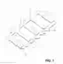
FIG. 1 is a schematic perspective top view of a vibration damping multilayer plate.
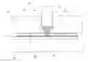
FIG. 2 is a cross-sectional view of the damping plate in FIG. 1.
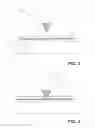
FIG. 3 is a schematic cross-sectional view of an embodiment of a punching tool ready for cutting a groove in a vibration damping plate according to a first embodiment of the method of the present invention.
FIG. 4 is a schematic cross-sectional view corresponding to that in FIG. 3 but where the cutting edge of the punching tool has selectively cut through the top rigid layer and the middle non-rigid layer of the damping plate.
FIG. 5 is a schematic cross-sectional view of a punch with an alternative design of the cutting edge.
FIG. 6 is a schematic cross-sectional view of another embodiment of punching tool ready for cutting a groove in a vibration damping plate according to a second embodiment of the method of the present invention.
FIG. 7 is a schematic cross-sectional view corresponding to that in FIG. 6 but where the cutting edge of the punching tool has selectively cut through the top rigid layer and the middle non-rigid layer of the damping plate.
DETAILED DESCRIPTION OF THE INVENTION
As mentioned above, the present invention is directed to a method for cutting through an outer rigid layer, and optionally also through one or more underlying non-rigid and rigid layer layers, respectively, of a multilayer laminate plate structure. An example of such a laminate plate structure is a vibration damping plate that includes an elastomer layer sandwiched between two metal sheets.
Cutting is an important working process in workshop practice where a sheet or rod is severed by shearing, cracking and finally breaking. A common cutting method is punching, as is used for example for cutting circular holes in a sheet metal. A simple punching tool consists of a punch and a die. The sheet metal is placed on the die, whereupon the punch acts upon the sheet metal with a certain force and the severance takes place, the sheet first being deformed by bending and then by shearing to finally crack and break when the point is reached at which the material can not be plastically deformed any further.
An example of a sandwich plate structure of the above-mentioned type, here specifically designed for damping of vibrations in an oil pan mounted to a combustion engine block, is illustrated in FIGS. 1 and 2, and is described in more detail in our co-pending international application entitled “Vibration damped article” (the entire disclosure of which is incorporated by reference herein), which claims priority from Swedish application no. 0850184-3.
The damping plate, generally designated by reference numeral 1, is designed to be attached to two opposed sidewalls of the oil pan (not shown) via a plurality of brackets positioned along the sidewalls of the oil pan some distance below its mounting surface to the engine block. To this end, the damping plate 1 is, in the illustrated case, provided with a number of apertures 2, each of which can receive an extending pin on each sidewall bracket (not shown). Other fastening means, such as screws or rivets, for instance, may of course, be used instead. The damping plate 1 is further provided with openings 3 for permitting rotation of the crankshaft when the oil pan is mounted to an engine block. The openings 3 delimit a number of connecting members 4 which connect one edge portion of the damping plate 1 with the opposite edge portion.
As can be seen from FIG. 2, the illustrated damping plate 1 is a sandwich laminate structure comprising a middle layer 5 of a non-rigid material, typically an elastomer, and upper and lower constraining layers 6, 7 of a rigid material, typically metal (or metal alloy). An exemplary damping plate consists of a rubber layer attached or bonded (e.g. vulcanized) between two steel sheets. Referring also to FIG. 1 again, in each connecting member 4 there is cut a cut line or groove 8 through the upper metal layer 6 and the middle elastomer layer 5 at least substantially up to the lower metal layer 7. Corresponding grooves 9 (FIG. 2) are cut in the lower metal layer 7, however, disposed at the opposite longitudinal edge portion of the damping plate 1.
Such provision of grooves 8, 9 thus divides each metallayer 6, 7, and optionally also the intermediate elastomer layer 5, into two separate (discontinuous) parts, i.e. a first part extending from one attachment side edge of the plate 1 up to the grooves, and a second part extending from the grooves up to the edge of the opposite attachment side of the damping plate, each metal/elastomer layer part being supported by the other metal layer. This division of each metal layer, and optionally the elastomer layer, into two separate parts supported by the other rigid layer will substantially reduce the rigidity of the damping plate and provide for efficient damping of vibrations. It is, however, not necessary that grooves 8, 9 are cut in each connecting member 4. For example, the grooves may be omitted in the outermost connecting member on each side of the damping plate.
The cuts 8, 9 in the metal layers 6, 7 may be made by conventional cutting methods like, for example, milling or sawing, which are based on removal of sheet material.
According to the present invention, however, narrow grooves 8, 9 are made without removal of sheet material by selectively punching through the respective metal layers 6, 7 and optionally into or through the elastomer layer, as will be described more generally below with reference to FIGS. 3, 4 and 5. It must be noted that in the following terms such as “vertical”, “upper” and “lower” are used merely with reference to the geometry of the embodiment of the invention shown in the figures and are not intended to limit the invention in any manner.
FIG. 3 schematically depicts a punching tool, generally designated by reference numeral 10, comprising an elongate punch 11 mounted (not shown) for vertical movement, and a die 14 with a planar top surface. The punch includes a cutting edge 15, which is shown here as being V-shaped. A multilayer vibration damping plate 1 is placed on the die 14. Merely for the purposes of illustration of the invention, the damping plate 1 is of the type described above which includes upper and lower metal sheets 6, 7 and an intermediate elastomer layer 5 (the same reference numerals as in FIGS. 1 and 2 are used). In FIG. 3, the punch 11 is in a position above the damping plate 1 placed on the die 14.
For clarity, the punching tool and damping plate illustrated in FIGS. 3 and 4 (as well as the punch depicted in FIG. 5) are not drawn to scale and are not in proportion.
FIG. 4 shows the punch 11 forced downwards in one operation such that the cutting edge 15 thereof has cut through the upper metal sheet 6 and the middle elastomer layer 5 down to the lower metal sheet 7 which may be touched as shown here or alternatively may be partially penetrated but which is not cut through in this operation.
For cutting the grooves 8, 9 in the damping plate 1, the cutting edge 15 of the punch 11 should have a length of at least the longitudinal extension of the damping plate as shown in FIG. 1. The separate grooves 8 (as well as the separate grooves 9) may be seen as forming a single cutting line together with the openings 3. Alternatively, the punch could have a plurality of spaced cutting edges corresponding to the separate grooves in the damping plate shown in FIG. 1. In still another alternative, the grooves 8 may be cut in separate cutting operations by a cutting edge of corresponding length.
Placing the laminate plate between the punch 11 and the die 14, as described above and shown in FIGS. 3 and 4, may, however, result in the upper metal layer on each side of the cutting edge being displaced laterally from the cutting line during the cutting operation since, as mentioned, no sheet material is removed—it is just displaced. This may in turn cause the metal sheet to curl or warp as well as risk displacing the fastening apertures 2 of the damping plate 1, if the latter are made before the cutting operation.
The metal sheet is therefore gripped, preferably immobilized, by appropriate lateral position retaining means on each side of the cutting edge of the punch to prevent lateral movement of the sheet portions during the cutting operation. This is illustrated in FIGS. 6 and 7, where corresponding parts have the same reference numerals as in FIGS. 3 and 4.
The punching tool shown in FIGS. 6 and 7, which is generally designated by reference numeral 20, differs from that in FIGS. 3 and 4 in that the punch 11 with cutting edge 15 is slidably mounted in a recess 12 of rectangular cross-section of a support 13. In FIG. 6, the punch 11 and the support 13 are in a position above the damping plate 1 placed on die 14.
The underside of the support 13 is provided with a number of gripping features, here barb-like ridges 16, extending in lines parallel to the cutting edge 15. When the damping plate is clamped against the die 14 by lowering the support 13, the ridges 16 are intended to cut into, and thereby grip, the topmost layer of the upper metal sheet 6 (FIG. 7). Various alternative gripping features, such as e.g. other pointed protrusions, as well as the pattern of their arrangement on the underside of the support 13, are readily apparent to the skilled person.
Similarly as in FIGS. 4 to 5, for clarity, the different parts are not to scale and are not in proportion.
FIG. 7 shows the punch 11 forced downwards in one operation such that the cutting edge 15 thereof has cut through the upper sheet 6 and the middle elastomer layer 5 down to the lower metal sheet 7 which may be touched as shown here or alternatively may be partially penetrated but which is not cut through in this operation.
During the cutting operation, the ridges 16 on support 13 effectively lock the upper sheet 6 material on either side of the cutting edge 15 against lateral displacement, resulting in a narrow cut of minimal width and with substantially no curling, warping or the like of the sheet surface.
As can be seen in FIG. 7, it is only the sheet material surface in the immediate vicinity of, i.e. immediately adjacent to, the cutting line that is slightly deformed when the cutting edge forces the sheet material laterally.
The term “immediate vicinity” in the present context is to be interpreted in a relatively broad sense, the sheet areas subject to plastic deformation depending inter alia on the extension of the bottom parts of support 13 towards the cutting edge on each side thereof. The distance, or spacing, between the support and the cutting edge is selected depending on the thickness and hardness of the sheet material to be cut. If the distance is too great, the cut material parts will not undergo any significant plastic deformation and the edges of the cut line will spring back with substantially no remaining deformation, i.e. no or a very thin cut line will be obtained. Too short a distance, on the other hand, may not leave enough room for the plastically-deformed material to flow into and may cause damage to the cutting edge.
For example, a vibration damping plate to be used in a conventional type internal combustion engine typically has a cutting line width at the top of the V-shaped cut (resulting from the V-shaped cutting edge) of the same order as, or less than, the depth of the cut e.g. 3 mm or less for a 3 mm thick plate. The width at the bottom of the cut should be greater than 0 mm so that the two sides of the split are close to each other but not in contact with each other, and is in practice often greater than 0.1 mm.
For such a cut, it has been found that with, for example, sheet steel of 1 mm thickness and moderate hardness, a distance from the cutting edge to the support on either side thereof of 8 mm will give a satisfactory result as there is sufficient plastic deformation to result in the desired cut width, whereas a distance of 20 mm gives an unsatisfactory result as there is no plastic deformation and the cut metal springs back into place.
The grooves 9 on the bottom metal sheet 7 of the damping plate 1 can be cut in a corresponding manner.
While the cutting edge 15 in FIGS. 3 and 4 is V-shaped with planar side faces, an alternative cutting edge design is shown in FIG. 5, where the cutting edge 15′ of the punch 11′ has side faces that are concave rather than V-shaped which reduces the amount of material that is displaced during the cutting operation and further reduces any tendency for curling, warping or the like.
Also, while the cutting of a groove in the form of a straight line has been described above, grooves having various alternative designs may be cut with a correspondingly designed cutting edge or edges, such as e.g. curved or wave- or zigzag-shaped, or a closed shape such as circular, elliptic, square or other polygonal shape.
Cutting a groove across a multilayer plate structure, such as the type described above, may also be used to facilitate bending of the plate structure along the groove. In the event that a V-shaped cutting edge is used, then if it is intended that the punched material is to be bent along the cut line then the angle of the V can be adapted to the angle that the material is intended to be bent though. For example if the material is to be bent through 90° then the angle of the V should preferably also be 90°.
The above described approach to cutting grooves in a sandwich damping plate may, of course, be applied to a variety of other situations where it is desired to make a partial cut through at least through a top rigid layer in multi-layer plate structures of various types, for example structures including more than two rigid layers with intermediate non-rigid layers.
The present invention is not limited to the above-described preferred embodiments. Various alternatives, modifications and equivalents may be used. Therefore, the above embodiments should not be taken as limiting the scope of the invention, which is defined by the appending claims.
Claims
1. A method of forming a cutting line partially through a multilayer plate structure comprising at least one rigid layer attached to a non-rigid layer, comprising the steps of:
a) placing the multilayer plate structure on a rigid support,
b) positioning a cutting edge towards the multilayer plate structure,
c) advancing the cutting edge towards a rigid layer,
d) placing lateral position retaining means in contact with the rigid layer surface on either side of the cutting edge,
e) cutting through at least the rigid layer but leaving at least one layer of the multilayer plate structure uncut, and holding the rigid layer by the lateral position retaining means to prevent lateral movement of the portion of the rigid layer between the rigid layer and the lateral position retaining means during the cutting operation.
2. The method according to claim 1, wherein the cutting in step e) is performed in a single operation.
3. The method according to claim 1, wherein deformation of the rigid layer surface caused by lateral movement of the rigid layer is at least substantially restricted to rigid layer areas in immediate vicinity of the cutting line.
4. The method according to claim 1 wherein the lateral position retaining means is designed to immobilize the rigid layer on either side of the cutting edge.
5. The method according to claim 4, wherein the cutting edge is part of a cutting element slidably mounted in a support having a planar bottom surface with protruding gripping means, and wherein gripping of the rigid layer is effected when the support is pressed against the multilayer plate structure.
6. The method according to claim 5, wherein the cutting element comprises a punch.
7. The method according to claim 1, further comprising cutting a single cutting line across the multilayer plate structure.
8. The method according to claim 1, further comprising cutting several separate cutting lines across the multilayer plate structure.
9. The method according to claim 1, wherein the multilayer plate structure comprises a non-rigid layer sandwiched between two rigid layers.
10. The method according to claim 9, further comprising cutting one or more cutting lines on each face of the multilayer plate structure.
11. The method according to claim 9, wherein the non-rigid layer is an elastomer, and the rigid layers are metal sheets.
12. The method according to claim 11, wherein the metal sheets are steel or aluminium sheets and the elastomer layer is rubber attached to the steel or aluminium sheets.
13. A multilayer plate structure having at least one cut made by the method according to claim 1.
14. The multilayer plate structure according to claim 13, characterized in that it is a vibration damping plate.
15. Use of the method according to claim 1 for producing a vibration damping plate.
16. Use of a vibration damping plate having at least one cut made by the method according to claim 1 in an automotive vehicle.
Images & Drawings included:


Sources:
- United States Patent and Trademark Office - verify current appl. status at the USPTO↗
Recent applications in this class:
- » 20250222611 2025-07-10
CUTTING APPARATUS AND METHOD FOR CUTTING A CAP - » 20240165840 2024-05-23
CUTTING DEVICE FOR CUTTING CAPSULES - » 20230381994 2023-11-30
Capsule cutting apparatus and method - » 20230001596 2023-01-05
Apparatus and method for producing a cutting geometry in a closure cap for a container - » 20220168917 2022-06-02
CUTTING APPARATUS AND METHOD FOR CUTTING A CAP - » 20200406487 2020-12-31
Device for machining distinctive marks on line - » 20190105790 2019-04-11
Score cutting tool - » 20170326749 2017-11-16
APPARATUS AND METHOD FOR CUTTING OR EMBOSSING COATINGS - » 20170259444 2017-09-14
Method and device for etching patterns inside objects - » 20170246755 2017-08-31
Cutting apparatus and method
Recent applications for this Assignee:
- » 20200309208 2020-10-01
Anti-squeal shim - » 20180274676 2018-09-27
Sealing cap and method for manufacturing a sealing cap - » 20150041055 2015-02-12
Anti-squeal shim - » 20150028547 2015-01-29
Methods and devices for cutting composite material and sealing devices made of composite material - » 20120067322 2012-03-22
Vibration damped article - » 20100140029 2010-06-10
Anti-squeal shim - » 20100140029 2010-06-10
Anti-squeal shim