HEAT SINK
US20120080169A1
2012-04-05
12/897,277
2010-10-04
Abstract:
A heat sink includes a fin set, a heat pipe and a fastener. The heat pipe has a heat-dissipating end and a heat-absorbing end. The heat-dissipating end is disposed through the fin set. The heat-absorbing end has a connecting side and a heat-absorbing side. The fastener has a body and a plurality of fixing ends. The body is assembled with the fin set. The center of the body is provided with at least one groove in such a manner that the heat-absorbing side protrudes from the groove directly to be brought into contact with a heat-generating element for thermal conduction. By this structure, thermal resistance is reduced while the thermal-conducting efficiency is increased.
Interested in similar patents?
Get notified when new applications in this technology area are published.
Classification:
F28D15/02 » CPC main
Heat-exchange apparatus with the intermediate heat-transfer medium in closed tubes passing into or through the conduit walls ; Heat-exchange apparatus employing intermediate heat-transfer medium or bodies in which the medium condenses and evaporates, e.g. heat pipes
F28D15/0275 » CPC further
Heat-exchange apparatus with the intermediate heat-transfer medium in closed tubes passing into or through the conduit walls ; Heat-exchange apparatus employing intermediate heat-transfer medium or bodies in which the medium condenses and evaporates, e.g. heat pipes Arrangements for coupling heat-pipes together or with other structures, e.g. with base blocks; Heat pipe cores
H01L23/427 » CPC further
Details of semiconductor or other solid state devices; Arrangements for cooling, heating, ventilating or temperature compensation ; Temperature sensing arrangements; Fillings or auxiliary members in containers or encapsulations selected or arranged to facilitate heating or cooling Cooling by change of state, e.g. use of heat pipes
H01L23/467 » CPC further
Details of semiconductor or other solid state devices; Arrangements for cooling, heating, ventilating or temperature compensation ; Temperature sensing arrangements involving the transfer of heat by flowing fluids by flowing gases, e.g. air
H01L23/3672 » CPC further
Details of semiconductor or other solid state devices; Arrangements for cooling, heating, ventilating or temperature compensation ; Temperature sensing arrangements; Selection of materials, or shaping, to facilitate cooling or heating, e.g. heatsinks; Cooling facilitated by shape of device Foil-like cooling fins or heat sinks
H01L2924/0002 » CPC further
Indexing scheme for arrangements or methods for connecting or disconnecting semiconductor or solid-state bodies as covered by; Technical content checked by a classifier Not covered by any one of groups , and
H01L2924/00 » CPC further
Indexing scheme for arrangements or methods for connecting or disconnecting semiconductor or solid-state bodies as covered by
F28D15/04 IPC
Heat-exchange apparatus with the intermediate heat-transfer medium in closed tubes passing into or through the conduit walls ; Heat-exchange apparatus employing intermediate heat-transfer medium or bodies in which the medium condenses and evaporates, e.g. heat pipes with tubes having a capillary structure
Description
BACKGROUND OF THE INVENTION
1. Field of the Invention
The present invention relates to a heat sink, and in particular to a heat sink which has a simple structure and is capable of preventing from generating thermal resistance.
2. Description of Prior Art
With the advancement of the semiconductor technology, the volume of each integrated circuit is gradually decreased. In order to make the integrated circuit to process more data, several times of calculating elements than before are mounted on the integrated circuit of the same volume. The more the number of the calculating elements in the integrated circuit is, the greater the heat generated by the calculating elements is. Taking a central processor as an example, the heat generated by the central processor in its full-load duty may burn down itself. Therefore, it is an important issue to develop a heat sink for the integrated circuit.
Currently, most of the heat sinks are made by metallic materials having a high coefficient of thermal conductivity. In order to enhance the heat-dissipating effect, a fan is used together with a fin set. Further, heat pipes may be used to facilitate the heat dissipation. With the above arrangement, the integrated circuit can be prevented from burning down.
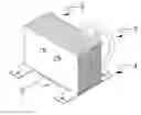
Please refer to FIG. 1, which is an assembled perspective view showing a conventional heat sink. As shown in this figure, the conventional heat sink 1 is constituted by a heat-dissipating base 11, a fin set 12 and at least one heat pipe 13. The heat-dissipating base 11 is provided with a tubular groove 111. One side of the fin set 12 is provided with a first fold 121 adhered to the heat-dissipating base 11. The first fold 121 has a curved notch 1211 corresponding to the tubular groove 111 of the heat-dissipating base 11.
During the assembly of the conventional heat sink 1, the heat pipe 13 is disposed in the tubular groove 111 of the heat-dissipating base 11. The fin set 12 is disposed on the heat-dissipating base 11 in such a manner that the curved notch 1211 of the first fold 121 of the fin set 12 is engaged with the heat pipe 13. In general, the connection between metallic materials is achieved by a soldering process. Therefore, the heat-dissipating base 11, the fin set 12 and the heat pipe 13 are assembled together by a soldering process. Thus, the first fold 121 of the fin set 12 is soldered to the heat-dissipating base 11. However, during the soldering process, some problems such as insufficient soldering, voids or waste of solders may happen. As a result, the thermal-conducting efficiency between the heat sink 1 and a heat source is reduced and a thermal resistance is generated. On the other hand, when a lot of thermal-conducting elements are assembled together, voids may often generate among the thermal-conducting elements, which increases the thermal resistance there between greatly.
According to the above, it is an important issue for the present Inventor and the manufacturers in this field to solve the problems of prior art.
SUMMARY OF THE INVENTION
In order to solve the above problems, an objective of the present invention is to provide a heat sink capable of reducing the thermal resistance between the heat sink and a heat source.
In order to achieve the above objective, the present invention provides a heat sink comprising a fin set, at least one heat pipe and at least one fastener. The fin set has a plurality of fins stacked up each other. Two opposite sides of the fin set are provided with a first fold and a second fold respectively. The heat pipe has a heat-dissipating end and a heat-absorbing end. The heat-dissipating end is disposed through the fins. The heat-absorbing end has a connecting side and a heat-absorbing side. The connecting side corresponds to the heat-absorbing side. The connecting side is brought into contact with the first side. The heat-absorbing side is brought into contact with at least one heat-generating element. The fastener has a body and a plurality of fixing ends. The fixing ends are formed by extending outwards from the body. The center of the body is provided with at least one groove. The body has a first side surface and a second side surface. The first side surface is connected to the first fold of the fin set. The first side surface is brought into thermal contact with the fin set and the heat-generating element via the connecting side and the heat-absorbing side of the heat pipe. With this arrangement, the thermal resistance is reduced while the thermal-conducting effect is increased. As a result, the heat sink has an excellent heat-dissipating effect.
According to the above, the present invention has the following advantageous features: (1) simple structure; (2) excellent heat-dissipating effect; and (3) little thermal resistance.
BRIEF DESCRIPTION OF THE DRAWINGS
FIG. 1 is an exploded perspective view showing a conventional heat sink;
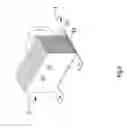
FIG. 2 is an exploded perspective view showing the heat sink according to an embodiment of the present invention;
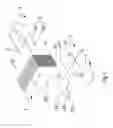
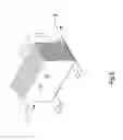
FIG. 3 is an assembled perspective view showing the heat sink according to the embodiment of the present invention;
FIG. 4 is an assembled perspective view showing the heat sink according to another embodiment of the present invention; and
FIG. 5 is an assembled perspective view showing the heat sink according to another embodiment of the present invention.
DETAILED DESCRIPTION OF THE INVENTION
The above objectives and structural and functional features of the present invention will be described in more detail with reference to preferred embodiments thereof shown in the accompanying drawings
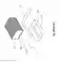
Please refer to FIGS. 2 and 3. The present invention provides a heat sink comprising a fin set 2, at least one heat pipe 3 and at least one fastener 4.
The fin set 2 has a plurality of fins 21 stacked up each other. Two opposite sides of the fin set 2 are provided with a first fold 22 and a second fold 23 respectively.
The heat pipe 3 has a heat-dissipating end 31 and a heat-absorbing end 32. The heat-dissipating end 31 is disposed through the fins 21. The heat-absorbing end 32 has a connecting side 321 and a heat-absorbing side 322. The connecting side 321 is opposite to the heat-absorbing side 322. The connecting side 321 is brought into contact with the first fold 22. The heat-absorbing side 322 is brought into contact with at least one heat-generating element 5.
The first fold 22 is provided with a curved groove 221 abutting against the contacting side 321 of the heat pipe 3.
The fastener 4 has a body 41 and a plurality of fixing ends 42. The fixing end 42 is formed by extending outwards from the body 41. The center of the body 41 is provided with at least one groove 411. The body 41 has a first side surface 412 and a second side surface 413. The first side surface 412 is connected to the first fold 22 of the fin set 2. The fixing end 42 of the fastener 4 further has at least one through-hole 421.
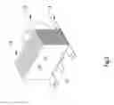
Please refer to FIG. 4, which is an assembled perspective view showing the heat sink according to another embodiment of the present invention. As shown in this figure, the fastener 4 further has an engaging end 43 engaged with the first fold 22 of the fin set 2. The fin set 2 is combined with the engaging end 43 of the fastener 4 by engagement.
Please refer to FIG. 5, which is an assembled perspective view showing the heat sink according to another embodiment of the present invention. As shown in this figure, the fin set 2 is combined with the fastener 2 by soldering.
Although the present invention has been described with reference to the foregoing preferred embodiments, it will be understood that the invention is not limited to the details thereof. Various equivalent variations and modifications can still occur to those skilled in this art in view of the teachings of the present invention. Thus, all such variations and equivalent modifications are also embraced within the scope of the invention as defined in the appended claims.
Claims
What is claimed is:1. A heat sink, including:
a fin set having a plurality of fins stacked up each other, two opposite sides of the fin set being provided with a first fold and a second fold respectively;
at least one heat pipe having a heat-dissipating end and a heat-absorbing end, the heat-dissipating end being disposed through the fins, the heat-absorbing end having a connecting side and a heat-absorbing side, the connecting side being opposite to the heat-absorbing side, the connecting side being brought into contact with the first fold, the heat-absorbing side being brought into contact with at least one heat-generating element;
at least one fastener having a body and a plurality of fixing ends, the fixing ends being formed by extending outwards from the body, the center of the body being provided with at least one groove, the body having a first side surface and a second side surface, the first side surface being connected to the first fold of the fin set.
2. The heat sink according to claim 1, wherein the fixing end of the fastener further has at least one through-hole.
3. The heat sink according to claim 1, wherein the first fold is provided with a curved groove abutting against the connecting side of the heat pipe.
4. The heat sink according to claim 1, wherein the fin set is combined with the fastener by means of soldering or engagement.
5. The heat sink according to claim 1, wherein the fastener further has an engaging end engaged with the first fold of the fin set.
Images & Drawings included:
Sources:
- United States Patent and Trademark Office - verify current appl. status at the USPTO↗
Similar patent applications:
- » 20170271238
Bonded body, power module substrate with heat sink, heat sink, method of manufacturing bonded body, method of manufacturing power module substrate with heat sink, and method of manufacturing heat sink - » 20170271237
Bonded body, power module substrate with heat sink, heat sink, method of manufacturing bonded body, method of manufacturing power module substrate with heat sink, and method of manufacturing heat sink - » 20180108593
Bonded body, substrate for power module with heat sink, heat sink, method for producing bonded body, method for producing substrate for power module with heat sink, and method for producing heat sink - » 20180040535
Bonded body, substrate for power module with heat sink, heat sink, method for producing bonded body, method for producing substrate for power module with heat sink, and method for producing heat sink - » 20180090413
Bonded body, substrate for power module with heat sink, heat sink, method for producing bonded body, method for producing substrate for power module with heat sink, and method for producing heat sink - » 20180068871
Bonded body, substrate for power module with heat sink, heat sink, method for producing bonded body, method for producing substrate for power module with heat sink, and method for producing heat sink - » 20070039726
Fin for a heat sink, heat sink and method for manufacturing a heat sink - » 20110281520
WIRELESS HEAT SINK, WIRELESS HEAT SINK SYSTEM AND WIRELESS HEAT SINKING METHOD FOR THE SAME - » 20140240989
Method of making a heat sink assembly, heat sink assemblies made therefrom, and illumants using the heat sink assembly - » 20110279968
Heat sink having auto switching function, heat sink system and heat sinking method for the same
Recent applications in this class:
- » 20250164193 2025-05-22
HEAT TRANSFER APPARATUS AND METHOD - » 20250123058 2025-04-17
MULTILAYER HIGH ASPECT RATIO MICROCHANNEL DEVICE - » 20240344772 2024-10-17
HEAT SINK APPARATUS - » 20240125558 2024-04-18
HEAT EXCHANGER - » 20240077259 2024-03-07
HEAT PIPES AND VAPOR CHAMBERS MANUFACTURED USING A VACUUM PROCESS - » 20230106794 2023-04-06
Heat sink - » 20220260319 2022-08-18
THERMOELECTRIC POWER GENERATION SYSTEM - » 20220214115 2022-07-07
Vapor chamber - » 20210318072 2021-10-14
Cooling device with superimposed fin groups - » 20210285728 2021-09-16
Immersion cooling system