CAM LINER PROFILE
US20120156077A1
2012-06-21
12/973,349
2010-12-20
Abstract:
A vane pump is provided and includes a liner having an inlet window and a discharge window, the liner being formed to define a cam surface and a rotor carrying a plurality of radially extending vanes which are forced outwardly such that vane tips thereof contact with the cam surface, the rotor having a direction of rotation such that one end of the inlet window is an upstream end and an opposed end is a downstream end, a radius of each of the vane tips being approximately 0.114 inches (0.3 cm) and a profile of the cam surface being defined in accordance with the radius of the vane tips.
Assignee:
- HAMILTON SUNDSTRAND CORPORATION 1,699 🇺🇸 Windsor Locks, CT, United States
Interested in similar patents?
Get notified when new applications in this technology area are published.
Classification:
F04C15/0011 » CPC main
Component parts, details or accessories of machines, pumps or pumping installations, not provided for in groups - ; Sealing arrangements in rotary-piston machines or pumps; Radial sealings for working fluid of rigid material
F01C21/0809 » CPC further
Component parts, details or accessories not provided for in groups - ; Rotary pistons Construction of vanes or vane holders
F01C21/106 » CPC further
Component parts, details or accessories not provided for in groups - ; Outer members for co-operation with rotary pistons; Casings; Stators; Members defining the outer boundaries of the working chamber with a radial surface, e.g. cam rings
F04C2/3442 » CPC further
Rotary-piston machines or pumps having the characteristics covered by two or more groups , , , or having the characteristics covered by one of these groups together with some other type of movement between co-operating members having the movement defined in groups or and relative reciprocation between the co-operating members with vanes reciprocating with respect to the inner member the inner and outer member being in contact along one line or continuous surface substantially parallel to the axis of rotation the surfaces of the inner and outer member, forming the working space, being surfaces of revolution
F01C19/04 IPC
Sealing arrangements in rotary-piston machines or engines; Radially-movable sealings for working fluids of rigid material
Description
BACKGROUND OF THE INVENTION
The subject matter disclosed herein relates to a vane pump having a unique cam liner profile.
Vane pumps typically include a rotor carrying a plurality of radially movable vanes. The vanes are urged outwardly into contact with a cam surface. The cam surface may be formed within a liner, which is mounted within an outer housing and which has a profile such that the cam surface has a similar profile.
The rotor is mounted eccentrically within the cam surface, such that the size of pump chambers increase and then decrease as the rotor moves from an inlet portion of a cycle toward a discharge portion. While the pump is moving through the inlet portion, fluid moves in through an inlet window and is then discharged through an outlet window after the pump cycle is completed.
There are stresses and forces on the vanes and the cam surface from the interacting movement and pressure differentials across the pump. There are particularly high contact stresses formed on the cam surface at areas associated with the inlet window and in particular at downstream ends of the inlet window.
BRIEF DESCRIPTION OF THE INVENTION
According to one aspect of the invention, a vane pump is provided and includes a liner having an inlet window and a discharge window, the liner being formed to define a cam surface and a rotor carrying a plurality of radially extending vanes which are forced outwardly such that vane tips thereof contact with the cam surface, the rotor having a direction of rotation such that one end of the inlet window is an upstream end and an opposed end is a downstream end, a radius of each of the vane tips being approximately 0.114 inches (0.3 cm) and a profile of the cam surface being defined in accordance with the radius of the vane tips.
According to another aspect of the invention, a vane pump is provided and includes a liner having an inlet window and a discharge window, the liner being formed to define a cam surface and a rotor carrying a plurality of radially extending vanes which are forced outwardly such that vane tips thereof contact with the cam surface, the rotor having a direction of rotation such that one end of the inlet window is an upstream end and an opposed end is a downstream end, a radius of each of the vane tips being approximately 0.150 inches (0.4 cm) and a profile of the cam surface being defined in accordance with the radius of the vane tips.
According to yet another aspect of the invention, a vane pump is provided and includes a liner having an inlet window and a discharge window, the liner being formed to define a cam surface and a rotor carrying a plurality of radially extending vanes which are forced outwardly such that vane tips thereof contact with the cam surface, the rotor having a direction of rotation such that one end of the inlet window is an upstream end and an opposed end is a downstream end, a radius of each of the vane tips being within a range of approximately 0.114 inches (0.3 cm) to approximately 0.150 inches (0.4 cm), inclusively, and a profile of the cam surface being defined in accordance with the radius of the vane tips.
These and other advantages and features will become more apparent from the following description taken in conjunction with the drawings.
BRIEF DESCRIPTION OF THE DRAWINGS
The subject matter which is regarded as the invention is particularly pointed out and distinctly claimed in the claims at the conclusion of the specification. The foregoing and other features, and advantages of the invention are apparent from the following detailed description taken in conjunction with the accompanying drawings in which:
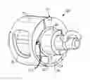
FIG. 1A shows a vane pump;
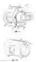
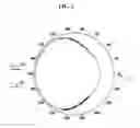
FIG. 1B shows a liner from the FIG. 1A vane pump;
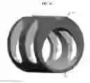
FIG. 1C shows a liner in accordance with further embodiments;
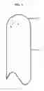
FIG. 2 shows an exemplary vane; and
FIG. 3 shows exemplary vane and cam liner profiles.
The detailed description explains embodiments of the invention, together with advantages and features, by way of example with reference to the drawings.
DETAILED DESCRIPTION OF THE INVENTION
A pump 20 is illustrated in FIG. 1A having a rotor 22 carrying a plurality of vanes 23 with vane tips 231. The vanes 23 are forced outwardly such that the vane tips 231 abut against a cam surface 26, shown here as part of a liner 25. The vanes 23 are oriented perpendicularly with respect to adjacent vanes 23. The liner 25 has a substantially eccentric cylindrical shape with the rotor 22 disposed in the liner 25 substantially parallel with a longitudinal axis of the liner 25. The liner 25 is typically mounted within a housing that has a supply of fluid to be pumped toward inlet window 28.
Pump chambers 24 are formed between the cam surface 26, and adjacent ones of the vanes 23. While not shown, the vanes 23 can move radially inwardly and outwardly of the rotor 22. The rotor 22 is mounted eccentrically within the liner 25 and driven to rotate such that the volume of the pump chambers 24 increases as it moves through an inlet portion of a pump cycle, and over the inlet window 28, and then begin to decrease in accordance with movement toward a discharge portion.
As shown in FIG. 1B, a discharge window 30 is formed circumferentially spaced from the inlet window 28. As shown in FIG. 1C, multiple discharge windows 30 may be formed circumferentially spaced from multiple inlet windows 28.
In standard models, a profile of the liner 25 (i.e., the “cam liner profile”) has been determined in accordance with a modified trapezoidal cam profile of standard vane tips. For certain applications, however, contact stresses between the vane tips 231 and the liner 25 were found to be excessively high. In accordance with aspects and, with reference to FIG. 2, reduction of the contact stresses is achieved by an increase of a radius, RT, of the vane tips. Normally, when the tip radius, RT, becomes too large, the vanes 23 are no longer able to follow the standard cam liner profile due to geometric constraints and, as a result, the vanes are pinched and lock inside the liner prohibiting further rotation. Here, on the other hand, the standard cam liner profile has been modified to allow for a larger vane tip radius and results in the reduced contact stress by as much as 26%.
With reference to Table 1, these modifications are provided in the “−6R114”, the “−4HR114” and the “−8R150” columns and in comparison to current, standard designs (i.e., the “−6”, the “−4H” and the “−8” columns)
| TABLE 1 |
| where the major and minor radii refer to transverse radii |
| of the cam liner profile and the displacement value is |
| calculated in accordance with the following equation: |
| Disp := [π · (R2 − r2) − 4 · (R − r) · t] · L |
| Model |
| −6 | −4H | −8 | ||||
| −6 | R114 | −4H | R114 | −8 | R150 | |
| Major Radius | 0.625 | 0.625 | 0.485 | 0.485 | 0.722 | 0.722 |
| (inch) R | ||||||
| Minor Radius | 0.425 | 0.425 | 0.365 | 0.365 | 0.492 | 0.492 |
| (inch) r | ||||||
| Vane Thickness | 0.093 | 0.093 | 0.093 | 0.093 | 0.093 | 0.093 |
| (inch) t | ||||||
| Vane Tip Radius | 0.062 | 0.114 | 0.062 | 0.114 | 0.114 | 0.150 |
| (inch) | ||||||
| Displacement | 0.5561 | 0.5561 | 0.4223 | 0.4223 | 1.21 | 1.21 |
| (in3/rev) | ||||||
That is, the “−4H”, the “−6” and the “−8” are all standard feature models and the “−6R114”, the “−4HR114” and the “−8R150” are modified with new tip radii and in some cases new vane lengths. For the “−6R114” and the “−4R114” cases, two vane elements are needed in order to meet minimum flow and, as such, the liner 25 of FIG. 1C may be used. By contrast, one vane element is enough to meet the minimum flow requirement in the “−8R150” case and, as such, the liner 25 of FIG. 1B may be used.
| TABLE 2 | ||||||
| Model | −6 | −6 R114 | −4H | −4H R114 | −8 | −8 R150 |
| Maximum Hertzian | 65.67 | 48.74 | 69.11 | 50.58 | 51.52 | 46.26 |
| Stress (Ksi) | ||||||
| Maximum PV Value | 1.029E+08 | 7.33E+07 | 1.032E+08 | 7.14E+07 | 1.12E+08 | 9.51E+07 |
| (psi-fpm) | ||||||
In addition, with reference to Table 2, while the “−4H” and “−6” standard models exhibited high characteristic Hertzian stresses and high PV values, both the “−4HR114” and the “−6R114” modified models had acceptable Hertzian stresses and PV values. Further, while the “−8” standard model and the “−8R150” modified model both had acceptable Hertzian stresses but high PV values, the “−8R150” model can be employed with reduced operational speeds to drop the PV value.
As described above and, in accordance with embodiments, the radii, RT, of the vane tips 231 have been increased to between 0.114 inches (0.3 cm) to 0.150 inches (0.4 cm), inclusively. In addition, the profile of the liner 25 has been modified as well. With reference to FIG. 3, the modification to the liner 25 profile is illustrated and, as shown in FIG. 3, it may be seen that the liner profile (i.e., r.cam(θ)) is similar to the profile of the tracing defined by the vane tips 231 (i.e., r.tip(θ)) as the rotor 22 rotates within the liner 25 up to about the 45 and the 315 degree regions, as measured from a top-dead center 251 of the liner 25. At the degree regions, the profiles diverge from one another. The profiles re-converge at around the 135 and the 225 degree regions. This has the effect of fattening the liner 25 profile around the 45-135 and the 315-225 degree regions.
With the profiles divergent from one another in the 45-135 and the 315-225 degree regions, the vanes 23 having increased vane tip 231 radii are removed from contact with the cam surface 26. This removal from contact reduces the stresses and the PV values of the modified models that would otherwise be generated.
While the invention has been described in detail in connection with only a limited number of embodiments, it should be readily understood that the invention is not limited to such disclosed embodiments. Rather, the invention can be modified to incorporate any number of variations, alterations, substitutions or equivalent arrangements not heretofore described, but which are commensurate with the spirit and scope of the invention. Additionally, while various embodiments of the invention have been described, it is to be understood that aspects of the invention may include only some of the described embodiments. Accordingly, the invention is not to be seen as limited by the foregoing description, but is only limited by the scope of the appended claims.
Claims
1. A vane pump comprising:
a liner having an inlet window and a discharge window, the liner being formed to define a cam surface; and
a rotor carrying a plurality of radially extending vanes which are forced outwardly such that vane tips thereof contact the cam surface, the rotor having a direction of rotation such that one end of the inlet window is an upstream end and an opposed end is a downstream end,
a radius of each of the vane tips being approximately 0.114 inches (0.3 cm) and a profile of the cam surface being defined in accordance with the radius of the vane tips.
2. The vane pump according to claim 1, wherein the plurality of the vanes comprises 4 vanes.
3. The vane pump according to claim 2, wherein each vane is perpendicular to an adjacent vane.
4. The vane pump according to claim 1, wherein the profile of the vane surface diverges from a profile of a tracing defined by each of the vane tips as the rotor rotates.
5. The vane pump according to claim 4, wherein the divergence occurs between the 45-135 and the 315-225 degree positions as measured from a top-dead center of the cam surface profile.
6. The vane pump according to claim 1, wherein the inlet window is formed as a plurality of inlet windows.
7. A vane pump comprising:
a liner having an inlet window and a discharge window, the liner being formed to define a cam surface; and
a rotor carrying a plurality of radially extending vanes which are forced outwardly such that vane tips thereof contact the cam surface, the rotor having a direction of rotation such that one end of the inlet window is an upstream end and an opposed end is a downstream end,
a radius of each of the vane tips being approximately 0.150 inches (0.4 cm) and a profile of the cam surface being defined in accordance with the radius of the vane tips.
8. The vane pump according to claim 7, wherein the plurality of the vanes comprises 4 vanes.
9. The vane pump according to claim 8, wherein each vane is perpendicular to an adjacent vane.
10. The vane pump according to claim 7, wherein the profile of the vane surface diverges from a profile of a tracing defined by each of the vane tips as the rotor rotates.
11. The vane pump according to claim 10, wherein the divergence occurs between the 45-135 and the 315-225 degree positions as measured from a top-dead center of the cam surface profile.
12. The vane pump according to claim 7, wherein the inlet window is formed as a singular inlet window.
13. A vane pump comprising:
a liner having an interior facing cam surface and being formed to define an inlet window and a discharge window; and
a rotor disposed within the liner and carrying a plurality of radially extending vanes which are forced outwardly such that vane tips thereof contact the cam surface during rotor rotation, the rotor having a direction of rotation such that respective one ends of the inlet and outlet windows are upstream ends and that respective opposed ends are downstream ends,
a profile of the cam surface being defined in accordance with the radius of the vane tips such that the profile diverges from a profile of a tracing defined by each of the vane tips as the rotor rotates.
14. The vane pump according to claim 13, wherein the plurality of the vanes comprises 4 vanes.
15. The vane pump according to claim 14, wherein each vane is perpendicular to an adjacent vane.
16. The vane pump according to claim 13, wherein a radius of each of the vane tips is approximately 0.114 inches (0.3 cm).
17. The vane pump according to claim 16, wherein the divergence occurs between the 45-135 and the 315-225 degree positions as measured from a top-dead center of the cam surface profile.
18. The vane pump according to claim 13, wherein the inlet window is formed as a plurality of inlet windows.
19. The vane pump according to claim 13, wherein a radius of each of the vane tips is approximately 0.150 inches (0.4 cm).
20. The vane pump according to claim 19, wherein the divergence occurs between the 45-135 and the 315-225 degree positions as measured from a top-dead center of the cam surface profile.
Images & Drawings included:
Sources:
- United States Patent and Trademark Office - verify current appl. status at the USPTO↗
Recent applications for this Assignee:
- » 20210381779 2021-12-09
Method for manufacturing a curved heat exchanger using wedge shaped segments - » 20210381438 2021-12-09
In flight restart system and method for free turbine engine - » 20210123695 2021-04-29
Heat exchanger with spray nozzle - » 20200182559 2020-06-11
Heat exchanger riblet and turbulator features for improved manufacturability and performance - » 20200077538 2020-03-05
Heat exchange device in directed flow system - » 20190212074 2019-07-11
Method for manufacturing a curved heat exchanger using wedge shaped segments - » 20190060828 2019-02-28
Temperature controlled nitrogen generation system - » 20190010874 2019-01-10
In flight restart system and method for free turbine engine - » 20180306234 2018-10-25
Foil bearing with split key - » 20180237144 2018-08-23
Two mode system that provides bleed and outside air or just outside air