Advanced high energy wave power module
US20120167563A1
2012-07-05
13/374,434
2011-12-28
✅ Patent granted
US 8,899,036 B2
2014-12-02
-
-
Thomas Denion | Mickey France
2032-03-19
Abstract:
An ADVANCED HIGH ENERGY WAVE POWER MODULE and each of the plurality of ADVANCED HIGH ENERGY WAVE POWER MODULES for converting the energy from high energy waves and swells into usable power in industrial scale connected by pressure piping, or by pressure piping and discharge piping, to the consumer of the mechanical energy in form of the high pressurized flow of working fluid is described as the submerged immovable platform and the submerged movable platform connected to the float by outer power flexible link with variable free length and compressible chambers installed between the immovable and movable platforms. The variable buoyancy force from the float converting to the increased driving force, which is acted through the movable platform to the compressible chambers to discharge high pressurized working fluid from compressible chambers through the pressure pipeline to the consumer. The stroke of the movable platform and compressible chambers is less than a height of wave or swells.
Inventors:
- Yuriy Cherepashenets 2 🇺🇸 Waltham, MA, United States
- Yakov Regelman 2 🇺🇸 Newton, MA, United States
Applicant:
Interested in similar patents?
Get notified when new applications in this technology area are published.
Classification:
Y02E10/30 » CPC further
Energy generation through renewable energy sources Energy from the sea, e.g. using wave energy or salinity gradient
Y02E10/30 » CPC further
Energy generation through renewable energy sources Energy from the sea, e.g. using wave energy or salinity gradient
F03B13/1855 » CPC main
Adaptations of machines or engines for special use; Combinations of machines or engines with driving or driven apparatus ; Power stations or aggregates characterised by using wave or tide energy using wave energy using the relative movement between a wave-operated member, and another member, where the other member, i.e. rem is fixed, at least at one point, with respect to the sea bed or shore and the wom slides relative to the rem where the connection between wom and conversion system takes tension and compression
F03B13/187 » CPC further
Adaptations of machines or engines for special use; Combinations of machines or engines with driving or driven apparatus ; Power stations or aggregates characterised by using wave or tide energy using wave energy using the relative movement between a wave-operated member, and another member, where the other member, i.e. rem is fixed, at least at one point, with respect to the sea bed or shore and the wom slides relative to the rem and the wom directly actuates the piston of a pump
F03B13/18 IPC
Adaptations of machines or engines for special use; Combinations of machines or engines with driving or driven apparatus ; Power stations or aggregates characterised by using wave or tide energy using wave energy using the relative movement between a wave-operated member, and another member, where the other member, i.e. rem is fixed, at least at one point, with respect to the sea bed or shore
F03B13/12 IPC
Adaptations of machines or engines for special use; Combinations of machines or engines with driving or driven apparatus ; Power stations or aggregates characterised by using wave or tide energy
Description
CROSS-REFERENCE TO RELATED APPLICATIONS
This application claims the benefit of Provisional Patent Application Ser. No. 61/460,252, filed Dec. 29, 2010 by the present inventors.
STATEMENT REGARDING FEDERALLY SPONSORED RESEARCH OR DEVELOPMENT
Not Applicable
BACKGROUND OF THE INVENTION
The following is a tabulation of some prior art that presently appears relevant:
| U.S. Patent |
| Pat. No. | Kind Code | Issue Data | Patentee | |
| 4,413,956 | A | Nov. 8, 1983 | Berg | |
| 4,630,440 | A | Dec. 23, 1986 | Meyerand | |
| 6,953,328 | B2 | Oct. 11, 2005 | Welch et al | |
| 7,059,123 | B2 | Jun. 13, 2006 | Welch et al | |
| 7,188,471 | B2 | Mar. 13, 2007 | Walters | |
| 7,216,483 | B2 | May 15, 2007 | Takeuchi | |
| 7,258,532 | B2 | Aug. 21, 2007 | Welch et al | |
| U.S Patent Application Publications |
| Publication Number | Kind Code | Publication Date | Applicant |
| 20070253841 | A1 | Nov. 1, 2007 | Burns |
| 20080231054 | A1 | Sep. 25, 2008 | Estefen |
| 20110042955 | A1 | Feb. 24, 2011 | Benson |
| 20110074159 | A1 | Mar. 31, 2011 | Stromotich |
Nonpatent Literature Documents
- “The Development of Wave Power”, National Engineering Laboratory, Glasgow, Scotland, 1976
- “Salter's duck”, New Scientist (IPC Magazines) 128, (1737-42): 26, 1990
- “Pelamis Offshore Wave Energy in Portugal”, Alternative Energy, 2006, 10, 08
- “Europe at the forefront in research on solar, wave and geothermal energies”, Press release IP/04/350, European Commission, 2004, 03, 16
This related to generating energy from water motion on the surface of the ocean, sea, or lake. In particular it relates to an advanced method and apparatus realized in Advanced High Energy Wave Power Module for converting energy from high energy swells and waves to useful forms of mechanical power.
The contemporary directions of generating clean energy without exhaust gases, which are polluted the atmosphere, are based mainly on converting directly solar energy or solar born wind energy into useful power. Both directions cannot compete economically with modern technology of generating power based on fossil fuel. The main reason of it is the low density, of power generated by solar or wind energy. For example maximum density of power generated by solar energy in a hot desert is around 320 watt per square meter. The modern offshore 5 MW wind turbine with diameter of blades up to 120 meters have the density of generated useful power around 440 watt per square meter of air space.
Density of power depends from density of medium that accumulates solar energy. As know the density of water almost 1000 higher than density of air. It is mean that water in form of swells and waves can accumulate much more solar energy than air in form of wind.
According Techno-Economic Study “The Development of Wave Power”, National Engineering Laboratory, Glasgow, Scotland, 1976 wave power is proportional to square of wave height and period of a wave and could be determinate from formula:
P=ρg2(H2T)/64π,
where is
ρ—density of water,
g—acceleration due to gravity,
H—significant wave height,
T—period of wave.
As example considers moderate ocean swells, in deep water, a few kilometers off a coastline, with a wave height of 3 meters and a wave period of 8 seconds the power of wave is 36 kW per meter of wave crest length.
Considerable power of wave attracts and impedes simultaneously of new technologies because turbulent forces of wave could damage or even destroy of the devices that convert energy of wave to useful power. But right direction of solving issues of transforming energy of high energy wave to useful power could bring society to new opportunity produce clean energy with efficiency comparable to modern power plant working on hydrocarbon fuels.
The largest numbers of prior art apparatus which have attempted to harness energy from the moved surface of the ocean have involved using devices which float and operate on the surface of the ocean to generate a mechanical or electrical power. These devices as Stephen Salter's Duck (“Salter's duck”, New Scientist (IPC Magazines) 128, (1737-42): 26, 1990), Pelamis Wave Energy Converter (“Pelamis Offshore Wave Energy in Portugal”, Alternative Energy, 2006, 10, 08) and Wave Dragon (“Europe at the forefront in research on solar, wave and geothermal energies”, Press release IP/04/350, European Commission, 2004, 03, 16) are operated with waves of moderate energy. In case of high energy waves the operation of the apparatus on a surface of ocean is restricted dying possible damaging or even destroying of apparatus by turbulent forces. Knowing another class of devices converting energy of waves into useful power, which based on a point absorber by the float that transfer energy of wave to transforming mechanism, which is submerged to prevent it from destroying by turbulent forces. These mechanisms could classifaid on two types, namely electrical generators, and hydraulic or pneumatic converters, particularly upstanding hydraulic cylinders that pumping water under pressure or pneumatic cameras in which air compressed by a variable height of passed waves.
Most advanced Power Buoy PB 150 developed by Ocean Power Technology is point absorber with diameter of the float around 10 meters connected to vertical submerged mechanism with height around 35 meters operated with wave between 1.5 meters and 7 meters height and generated maximum peack-rated of 150 kW electrical power. Such height of mechanismus was determinated by direct driving from float to generator. Both U.S. Pat. No. 4,413,956 A to John I. Berg (1983) and U.S. Pat. No. 6,953,328 B2 (2005) to Welch, Jr. have shown the method and apparatus to utilize the energy of waves on the base wave pump apparatus using upstanding cylinders with the piston connected directly to the moving float or buoyancy block.
Converting wave energy into useful energy using submersible hydraulic cylinders, pistons or housing cylinder that are driven by the float are practically possible only for waves of moderate height with a moderate energy level because it is impractical to have submerged cylinders with the stroke 3 or more meters.
Disadvantages of the submersible hydraulic cylinders for wave energy converting are following:
-
- The long stroke of the movable part of the hydraulic cylinder is equal to the movement up and down of the float, which is moved under the action of waves, such if wave height of three meters so the movable part of the cylinder should also move to three meters. Manufacturing of such hydraulic cylinders is a difficult technical challenge and expensive;
- Losses of energy due the friction of motion in a pair of housing cylinder-piston, which reduces the efficiency of conversion of wave energy into useful energy;
- The maintenance of hydraulic cylinders, including replacement of seals in the movable joints operating in salt water, which would require dismantling and disassembly of hydraulic cylinders.
For high energy capacity waves with height up to seven meters and more using of hydraulic cylinders is more impractical because the cost of such devices and their reliability will not compete with modern methods of energy generation.
U.S. Pat. No. 4,630,440 A to Meyerand (1986) has shown a method and apparatus for converting wave energy into useful energy using submersible low-pressure compressible chambers. Variable compression in chambers due to change in hydrostatic pressure of the water column above the compressible chambers during the passage of the waves.
Disadvantages of the low pressure compressible chambers for wave energy converting are following:
-
- Low water pressure in the hydraulic turbine due to low fluctuation of hydrostatic pressure during the passage of the waves. If the height of the wave is three meters so an increment of pressure in compressible chambers is only approximately 0.3 bar;
- Losses due to friction with the transport of water through the piping that are may be significant comparable to increment of pressure 0.3 bar;
- Low efficiency of conversion of wave energy into usable energy.
BRIEF SUMMARY OF THE INVENTION
The above identified problems are solved by the method and apparatus of Advanced High Energy Wave Power Module and plurality of Advanced High Energy Wave Power Modules disposed according to mode of passing high energy swells and waves and submerged in a surrounding body of water to a depth at which the water is under a selected pressure.
In a first embodiment of an Advanced High Energy Wave Power Module provides a method of converting power of high energy swells and waves into useful power in the form of the high pressurized flow of working fluid to the consumer of mechanical power. This method comprises:
-
- transforming high amplitude movement of the float on high energy swells and waves into selected small stroke of a submerged movable platform relative to the submerged immovable platform, and the corresponded small stroke of the upstanding compressible chambers mounted by the upper bases on the immovable platform and by the lower bases on the movable platform,
- transforming buoyancy force of the float to the increased driving force acting to the movable platform, which will compress the compressible chambers with the force equal to he buoyancy force multiplied on the ratio of the design high amplitude movement of the float to the selected small stroke of the movable platform,
- producing high pressurized working fluid discharged from the upstanding compressible chambers working in parallel,
- summarizing of flows of high pressurized working fluid from plurality of Advanced High Energy Wave Power Modules,
- transporting summarized flow of high pressurized working fluid to a consumer of mechanical power, which could be hydraulic turbine-generator, hydraulic turbine-compressor, reservoir of peak power plant, or desalinated station.
Generated power could be used also as balance of output power of the wind farm, when velocity of wind decreased, but swells and waves still passing through the area of wind farm.
In a second embodiment of an Advanced High Energy Wave Power Module provides an apparatus to convert power of high energy swells and waves into useful power in the form of the high pressurized flow of working fluid to the consumer of mechanical power. The apparatus comprises:
a float jointed to the upper end of an outer power flexible link,
an outer power flexible link with the variable length directed by guide roller to a pulley-converter with the circumference of equal to or more than the design height of a wave, and jointed by the lower end to a pulley-converter mounted rigidly on a common with driving pulleys rotated shaft, which is mounted rigidly through the brackets on an immovable platform,
the immovable platform connected to on a supporting structure submerged in a surrounding body of water to a depth at which water is under selected pressure,
the movable platform, which has the selected upward and downward stroke relative to said immovable platform, such that the selected upward and downward stroke is less than the design height of a wave in times equal to the ratio of the diameter of the pulley-converter to the diameter of the driving pulley,
compressible chambers with variable volumes and spring-loaded compression of bodies upstanding in parallel and jointed by their upper bases to the immovable platform and their lower bases to the movable platform,
at least two driving pulleys with the circumference of equal to or more than the selected stroke of the movable platform, which is mounted rigidly on the common rotated shaft with the pulley-converter,
at least two inner driving flexible links with variable length jointed by the each upper end to each driving pulley correspondently and jointed by the each lower end to the movable platform,
the cavities of the compressible chambers with variable volumes filled with working fluid connected through the pressure openings in the upper bases, pressure conduits to the inlet of at least one pressure check valve and through the suction openings in the upper bases, suction conduits connected to the outlet of at least one suction check valve,
at least one pressure check valve, which outlet is connected hydraulically through the pressure piping to the consumer of useful power in the form of the discharged flow of the high pressurized working fluid, when the pressure check valve is opened and the suction check valve is closed and disconnected hydraulically the cavities to a source of the working fluid under action of an increased pressure inside of the cavities under action by the driving force, when the float moving upward under action of passing swells and waves,
at least one suction valve, which inlet is connected hydraulically to the one of the sources of the working fluid wherein the working fluid is sucked into the cavities under action of a difference pressures of said source of a working fluid and a pressure inside the cavities, when the suction check valve is opened and connected hydraulically a source of the working fluid to the cavities, and the pressure check valve is closed and disconnected hydraulically to the consumer of useful power under action of a lowered pressure inside the cavities, when the float moving downward under action of own weight,
jointed to the supporting structure plurality of Advanced High Energy Wave. Power Modules, which each of them are connected through the suction check valves to source of working fluid, and through the pressure check valves to the pressure piping, which is connected to the consumer of useful energy in the form of summarized flow of the high pressurized working fluid.
As the result of improvements Advanced High Energy Wave Power Module and plurality of them disposed in surrounding body of water to a depth at which the water is under the selected pressure and with configuration of layout according to the selected model of swells and waves have following advantage:
-
- operating in the rough ocean conditions with high energy swells and waves,
- producing high pressurized flow of working fluid from high energy swells and waves with selected small stroke of the mass production compressible chambers.
BRIEF DESCRIPTION OF DRAWINGS
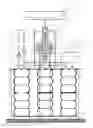
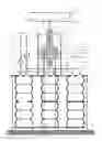
FIG. 1 is a diagram of the Advanced High Energy Wave Power Module
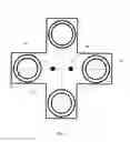
FIG. 2 is a sectional plan view of the compressible chambers on the submerged movable platform
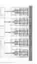
FIG. 3 is a diagram of the example of plurality of the Advanced High Energy Wave Power Modules jointed to the supporting structure.
DRAWINGS
Reference Numerals
-
- 10. Mooring point of the submerged immovable platform
- 11. Submersed movable platform
- 12. Lower bases of the compressible chambers
- 13. Compressible chambers or assemblies of the series-connected compressible chambers
- 14. Connected lower bases of the assemblies of the series-connected compressible chambers
- 15. Connected upper bases of assemblies of series-connected compressible chambers
- 16. Opening in connected bases of assemblies of series-connected compressible chambers
- 17. Submerged immovable platform
- 18. Upper bases of the compressible chambers
- 19. Suction openings of the compressible chambers
- 20. Suction piping
- 21. Pressure openings of the compressible chambers
- 22. Pressure piping
- 23. Suction check valve
- 24. Suction piping
- 25. Pressure check valve
- 26. Pressure piping
- 27. Discharge piping from the consumer
- 28. Pressure piping to the consumer
- 29. Consumer
- 30. Float
- 31. Outer power flexible link with variable free length
- 32. Guide roller
- 33. Shaft of the guide roller
- 34. Bearing of the guide roller
- 35. Pulley-converter connected to outer power flexible link
- 36. Driving pulleys connected to inner driving flexible links with variable free length
- 37. Bearing of the pulley-converter and the driving pulleys
- 38. Shaft of the pulley-converter and the driving pulleys
- 39. Inner driving flexible links with variable free length
- 40. Pressure piping connected pressure openings of the compressible chambers
- 41. Suction piping connected suction opening of the compressible chambers
- 42. Brackets
- 43. Cavities of compressible chambers
- 44. Source of water
- 45. Legs of the immovable platform
- 46. Supporting structure
- 47. Advanced High Energy Wave Power Module
DETAILED DESCRIPTION OF THE INVENTION
Generating power in an efficient way from sources of renewable energy is important as traditional energy sources are depleting and there is increasing thermal and chemical pollution of the environment.
The Advanced High Energy Wave Power Module is relates to the method and apparatus for converting renewable energy of high energy swells and waves to useful mechanical power in form of high pressurized flow of working fluid to the consumer, which could be hydraulic turbine-generator, hydraulic turbine-compressor, reservoir of peak power plant, or desalinated station.
Generated power could be used also as balance of output power of the wind farm, when velocity of wind decreased, but swells and waves still passing through the area of wind farm.
-
- In condition of rough ocean there is ensured operation of Advanced High Energy Wave Power Module and plurality of Advanced High Energy Wave Power Modules connected hydraulically to the consumer with three advantaged steps are developed:
- Advanced High Energy Wave Power Modules are submerged in a surrounding body of water to a depth at which the water is under a selected pressure, which excluded destroying action of the turbulent forces of the high energy swells and waves to apparatus
- providing the selected small stroke of the compressible chambers that improved operation conditions of the compressible chambers, when the float moving upward and downward with high amplitude corresponded to the high energy swells and waves,
- providing increased driving force on the compressible chambers is allowed to produce high pressurized flow of working fluid to the consumer and to increase the efficiency transforming of energy waves to useful power.
- Another three advantaged steps that are also developed:
- transforming energy of high energy swells and waves into useful power in form of high pressurized flow of working fluid is allowed to use different applications of the Advanced High Energy Wave Power Modules as example for supplying hydraulic turbine-generator, hydraulic turbine-compressor, reservoir of peak power plant, or desalinated station.
- Generated power could be used also as balance of output power of the wind farm, when velocity of wind decreased, but swells and waves still passing through the area of wind farm.
- Plurality of Advanced High Energy Wave Power Modules jointed to the supporting structure could be used also as system, which could operate close to coast line to produce useful power and simultaneously to prevent a coast line from destroying from action of high energy swells and waves.
- In condition of rough ocean there is ensured operation of Advanced High Energy Wave Power Module and plurality of Advanced High Energy Wave Power Modules connected hydraulically to the consumer with three advantaged steps are developed:
The Advanced High Energy Wave Power Modules could be connected with the consumer 29 of mechanical power in form of high pressurized flow of fluid with to options:
-
- an open loop of circulated water,
- a closed loop of circulated working fluid.
When the Modules are connected in the open loop the outlet 27 of consumer 29 is disconnected to the suction pipe 24, such that the water from consumer 29 discharged back to the source of water 44. The suction of the water from the source of water 44 to the compressible chambers 13 will be run through the suction pipe 24 and the opened suction check valve 23 under action of the difference pressures in the source of water 44 on the selected deep and in the cavities 43 of compressible chambers 13.
When the Modules are connected in the closed loop the outlet 27 of consumer 29 is connected to the suction pipe 24, such that the working fluid from consumer 29 is discharged back to the compressible chambers 13 through the suction pipe 24 and the opened suction check valve 23 under action of the difference pressures in the source of water 44 on the selected deep and in the cavities 43 of compressible chambers 13.
In case of the closed loop the impact on the environment will be minimized, because the working fluid remains inside of the closed loop and only transferring energy from high energy swells and waves to the consumer 29 in form of high pressurized flow of the working fluid through the pressure piping 26.
The Advanced High Energy Wave Power Module has the submerged immovable platform 17 and the submerged movable platform 11.
There are two options:
-
- a. Submerged immovable platform 17 fixed rigidly through the legs 45 to the mooring points, as example to ocean floor, or to the some supporting structure 46,
- b. Submerged immovable platform 17 connected with flexible link to the mooring point 10, as example as anchor to ocean floor, or to the corresponding supporting structure 46 immovable relatively to the ocean floor. In this case submerged immovable platform with all equipment installed on the platform, excluding the float, must have the self-positive buoyancy in working conditions under the full load of fluid in the compressible chambers.
FIG. 1 is the diagram of the configuration of the Advanced High Energy Wave Power Module that comprises:
-
- Submerged immovable platform 17 connected through the mooring points 10 to the supporting structure 44 and with installed on the platform 17 following equipment:
- Rotated pulley-converter 35 rigidly connected to the shaft 38 with the bearings 37, which are rigidly jointed through the brackets 42 the to the submerged immovable platform 17,
- Rotated guide roller 32 rigidly connected to the shaft 33 with bearings 34, which are rigidly jointed through the brackets 42 the to the submerged immovable platform 17
- Rotated driving pulleys 36 rigidly connected to the shaft 38,
- The outer power flexible link 31 with variable free length is fixed by the lower end to the pulley-converter 35, passing through the guide roller 32, and connected by the upper end to the float 30,
- The inner driving flexible links 30 with variable free length are fixed by the upper ends to the corresponded driving pulleys 36 and by the lower ends to the submersed movable platform 11,
- Pressure piping 22, 40 that connected all outlet openings 21 of the compressible chambers 13 and connected to the pressure check valve 25 connected to the pressure piping 26 and to the pressure piping 28 of the consumer 29,
- Suction piping 20, 41 that connected all suction openings 19 of the compressible chambers 13 and connected to the suction check valve 23 connected to the suction piping 24 and to the discharge piping 27 of the consumer 29;
- Upstanding compressible chambers 13 with the variable volume of the cavities 43 are located between the submerged immovable platform 17 and the submerged movable platform 11;
- Compressible chambers 13 are mounted in parallel to each other on the submersed movable platform 11 and may consist from the assemblies of series-connected between each other of the compressible chambers 13. The series-connected compressible chambers 13 have common internal cavities through openings 16 in the connected bases 14, 15;
- Upper bases 18 of compressible chambers 13, or assemblies of series-connected compressible chambers 13, are installed on the submerged immovable platform 17.
- Lower bases 12 of compressible chambers 13 are installed on the submersed movable platform 11,
- Upper bases 18 of the compressible chambers 13 with pressure openings 21 are connected in parallel through the pressure piping 31 to the pressure check valve 25 that connected to pressure piping 26, which is connected to the pressure piping 28 of the consumer 29,
- Suction openings 19 of the compressible chambers 13 are connected in parallel through the suction piping 41 to the suction check valve 23 and suction piping 24, which is connected to the discharge piping 27 of the consumer 29;
- Submerged immovable platform 17 connected through the mooring points 10 to the supporting structure 44 and with installed on the platform 17 following equipment:
FIG. 2 is a sectional plan view of the compressible chambers 13 on the submerged movable platform 11. Number of the compressible chambers 13 shown on the FIG. 2 is four (4). This number and the disposition of the compressible chambers 13 on the submerged movable platform 11 may be variable. The configuration of the submerged movable platform 11 will be change correspondently.
FIG. 3 is a diagram of the example of plurality of the Advanced High Energy Wave Power Modules 47 jointed by the legs 45 to the supporting structure 46. Such block could be manufactured as complete unit and delivery to the field site for final assembly with others blocks to produce and transport summarized flow of high pressurized working fluid in the industrial scale to the consumer.
Operation
Extraction of the portion of useful energy from energy of the passing waves and swells when the float 21 is moving upward comprises:
-
- Increasing the buoyancy force on the float 30 and increasing the force of the tension on the outer power flexible link 31;
- Rotating the pulley-converter 35 connected to the outer power flexible link 31 and driving pulleys 36 rigidly connected to the shaft 38, and increasing the free length of the outer power flexible link 31 between the float 30 and the guide roller 32;
- Unbalancing the momentums acting on the pulley-converter 35 from increased buoyancy force on the float 30 and from the tension force acting on the inner driving flexible links 39 connected to the driving pulleys 36 and the submerged movable platform 11;
- Moving upward of the submerged movable platform 11 with increasing pressure of working fluid in the compressible chambers 13 and increasing the spring-loaded force of compression associated with compressible chambers 13 to balance momentums acting on the pulley-converter 35 and driving pulleys 36 in new equilibrium position of the float 30 and the submerged movable platform 11;
- Rotating of the driving pulleys 36 and reducing the free length of the inner driving flexible links 39 between the submerged movable platform 11 and driving pulleys 36;
- Opening of the pressure check valve 25 under increased pressure in cavities 43 of the compressible chambers 13 and discharging a portion of high pressurized working fluid from the cavities 43 through the pressure openings 21, pressure piping 22, pressure piping 40 and pressure check valve 25 to the pressure piping 26 connected to the pressure piping 28 of the consumer 29;
- Repetition of the process of the discharging of high pressurized working fluid to the consumer 29 during passage of waves and swells, when the float 30 is moving upward.
Moving the float 30 downward will activate the process of suction working fluid to the cavities 43 of the compressible chambers 13 from suction piping 24 connected from one side to discharge piping 27 of the consumer 29, or to working fluid source, and from another side to the suction check valve 23 connected to the suction piping 41, suction conduits 20 and suction openings 19 of the cavities 43.
The suction of working fluid to the cavities 43 comprises:
-
- Decreasing the buoyancy force on the float 30 moving downward and decreasing the force of the tension on the outer power flexible link 31 connected to the pulley-converter 35;
- Balancing the momentum acting on the pulley-converter 35 from decreased buoyancy force on the float 30 and the momentum acting on the driving pulleys 36 from the increased tension force from the spring-loaded force associated with the compression of the compressible chambers 13 acting on the inner driving flexible links 39 connected to the driving pulleys 36 and to the submerged movable platform 11 leading to a new equilibrium position of the float 30 and the submerged movable platform 11;
- Moving downward of the submerged movable platform 11 accompanied increasing volumes of the cavities 43 and reduction pressure of fluid in the compressible chambers 13;
- Rotating the pulley-converter 35 in opposite direction and decreasing the free length of the outer power flexible link 31 between the float 30 and the guide roller 32;
- Rotating of the pulley-converter 35 to the opposite direction and increasing the free length of the inner driving flexible links 39 between the submerged movable platform 11 and driving pulleys 36;
- Opening of the suction check valve 23 under action of different pressures in the suction piping 24 and the cavities 43,
- Suction of the working fluid from discharge piping 27 of the consumer 29, or from source of working fluid, through the suction check valve 23, suction openings 19 in the upper bases 9 into cavities 43 of the compressible chambers 13;
- Leading the process of the suction until to a new equilibrium position of the float 30 and the submerged movable platform 11;
- Repetition of the process of the suction of fluid to the cavities 43 of the compressible chambers 13 during passage of waves and swells, when the float 30 is moving downward.
Plurality of the Advanced High Energy Power Modules connected to the consumer 29 will supply the high pressurized flow of working fluid in industrial scale the consumer 29 during passage of waves and swells.
It is obvious that the present invention is not restricted to the embodiments presented above. The present invention can be modified within the basic idea to include summarizing additional ideas for using extracted energy from waves and swells as a mechanical energy, or as source of accumulated energy in different kind of medium as some fluids, or water, or air under pressure.
Claims
We claim:1. A method for generating energy from the energy sources of swells and waves, comprising:
a. providing a float jointed to upper end of an outer power flexible link with a variable free length moving upward under the action of passing swells and waves and downward under action of its own weight,
b. providing an increase of the free length of said outer power flexible link jointed by the lower end to a pulley-converter through the reeling off said outer power flexible link from said pulley-converter, when said float is moving upward,
c. providing a decrease of the free length of said outer power flexible link through the reeling up said outer power flexible link on said pulley-converter, when said float is moving downward,
d. providing a transfer of a buoyancy force of said float moving upward through said outer power flexible link to said pulley-converter mounted on a rotated shaft, which is fixed with brackets to an immovable platform submerged in a surrounding body of water to a depth at which the water is under a selected pressure,
e. transforming of said buoyancy force of said float moving upward to a torque on said shaft proportional to the diameter of said pulley-converter and said buoyancy force,
f. providing such size of said diameter such that the circumference of said pulley-converter would be equal to or greater than the design height of a wave,
g. providing at least two driving pulleys with equal diameters and at least two inner driving flexible links with a variable free length working in parallel and connected by an each upper end to said corresponded driving pulley fixed rigidly on said rotated shaft, which is common with said pulley-converter, and by lower ends to a movable platform submerged in a surrounding body of water to a depth at which the water is under a selected pressure, such that the free length of said inner driving flexible links will be decreasing by reeling up on said driving pulleys when said float will move upward,
h. providing an amplified driving force on said inner driving flexible links comparable to buoyancy force on said outer power flexible link converting said torque on said shaft to said driving force according to a ratio of said diameter of said pulley-converter to a diameter of said driving pulley,
i. providing such size of said diameter of said each driving pulley, such that the circumference of said driving pulley would be equal to or greater than the selected stroke of a movable platform relative to said immovable platform,
j. transferring said amplified driving force through said inner driving flexible links to said movable platform connected to said immovable platform through the compressible chambers filled with a working fluid, jointed to said immovable platform by upper bases and jointed to said movable platform by lower bases, submerged in a surrounding body of water to a depth at which the water is under a selected pressure,
k. providing a stroke of said movable platform upward to said immovable platform under an action of said amplified driving force on said inner driving flexible link, when said float is moving upward under action of passing waves,
l. providing a decrease of said stroke of said movable platform relative to said immovable platform in comprising to the wave height according to the ratio of said diameter of said pulley-converter to said diameter of said driving pulley,
m. converting said driving force of said inner driving flexible link to spring-loaded compression of bodies of said compressible chambers and the high pressure of said working fluid in the cavities of said compressible chambers, such that a pressure check valve hydraulically connected with said cavities will open for discharge high pressurized working fluid to pressure piping, when said float is moving upward under action of passing waves,
n. transporting to a consumer of useful power an extracted portion of useful power in form of a flow of said high pressurized working fluid discharged from said cavities of said compressible chambers through said pressure check valve, said pressure piping, when under action of said amplified driving force said movable platform is moving upward to said immovable platform, a volume of said cavities is decreased and spring-loaded compression of bodies of said compressible chambers is increased, said driving pulleys are rotated under action of buoyancy force and decreased free length of inner driving flexible links by reeling up of said inner driving flexible links on said driving pulleys, when said float is moved upward,
o. providing a suction of said working fluid from a source of said working fluid, which said source is hydraulically connected to the inlet of a suction check valve and through the outlet of said suction check valve into said cavities, when under action of a selected pressure in the source of said working fluid said suction check valve is opened, when under action of said spring-loaded compression of bodies of said compressible chambers said movable platform is stroked downward relative to said immovable platform, said driving pulleys are rotated and increased free length of inner driver flexible links accompanied by increasing of the volume of said cavities, reducing the pressure inside said cavities, closing said pressure check valve under action of a backward pressure of said working fluid in said pressure piping, when said float is moved downward,
p. transferring a force of said spring-loaded compression of bodies of said compressible chambers through said inner driving flexible links, said driving pulleys, which are fixed on said common rotated shaft with said pulley-converter under action of said force, such that the free length of said outer power flexible link is reducing by reeling up on said pulley-converter under action of said spring-loaded force, when said float is moving downward,
2. A method as claimed in claim 1 wherein a source of said working fluid is surrounding a body of water with the selected pressure of equal to the height of the water column from the surface water level to said suction check valve for the open loop of the circulated water,
3. A method as claimed in claim 1 wherein a source of said working fluid is said source of any selected working fluid returned back from the consumer of useful power with selected lowered pressure through said suction piping connected to the outlet of said consumer from one side and from another side to said inlet of said suction check valve hydraulically connected to said cavities of said compressible chambers for the closed loop of the circulated working fluid,
4. A method as claimed in claim 1 wherein an extracted portion of useful power in form of a flow of said high pressurized working fluid discharged from said cavities of said compressible chambers, which is transported to the consumer through pressure piping, there are summarized extracted portions of useful power in form of a flows of said high pressurized working fluid discharged from plurality of Advanced High Energy Wave Power Modules disposed in surrounding body of water to a depth at which the water is under the selected pressure and with configuration of layout according to the selected model of swells and waves that will provide operation of Advanced High Energy Wave Power Modules,
5. An apparatus of an Advanced High Energy Wave Power Module and each of plurality of said Advanced High Energy Wave Power Modules for generating energy in industrial scale from energy source of swells and waves, said apparatus comprising:
a float jointed to the upper end of an outer power flexible link,
an outer power flexible link with the variable length directed by guide roller to a pulley-converter with the circumference of equal to or more than the design height of a wave, and jointed by the lower end to a pulley-converter mounted rigidly on a common with driving pulleys rotated shaft, which is mounted rigidly through the brackets on an immovable platform,
said immovable platform connected to on a supporting structure submerged in a surrounding body of water to a depth at which water is under selected pressure,
said movable platform, which has the selected upward and downward stroke relative to said immovable platform, such that said selected upward and downward stroke is less than the design height of a wave in times equal to the ratio of the diameter of said pulley-converter to the diameter of said driving pulley,
compressible chambers with variable volumes and spring-loaded compression of bodies upstanding in parallel and jointed by their upper bases to said immovable platform and their lower bases to said movable platform,
at least two driving pulleys with the circumference of equal to or more than the selected stroke of said movable platform, which is mounted rigidly on said common rotated shaft with said pulley-converter,
at least two inner driving flexible links with variable length jointed by the each upper end to each driving pulley correspondently and jointed by the each lower end to said movable platform,
said cavities of said compressible chambers with variable volumes filled with working fluid connected through the pressure openings in said upper bases, pressure conduits to the inlet of at least one pressure check valve and through the suction openings in said upper bases, suction conduits to the outlet of at least one suction check valve,
at least one said pressure check valve, which outlet is connected hydraulically through the pressure piping to the consumer of useful power in the form of the discharged flow of the high pressurized working fluid, when said pressure check valve is opened and said suction check valve is closed and disconnected hydraulically said cavities to a source of the working fluid under action of an increased pressure inside of said cavities under action by said driving force, when said float moving upward under action of passing swells and waves,
at least one said suction valve, which inlet is connected hydraulically to the one of the sources of said working fluid as claimed in claims 2 and 3 wherein the working fluid is sucked into said cavities under action of a difference pressures of said source of a working fluid and a pressure inside said cavities, when said suction check valve is opened and connected hydraulically a source of said working fluid to said cavities, and said pressure check valve is closed and disconnected hydraulically to the consumer of useful power under action of a lowered pressure inside said cavities, when said float moving downward under action of own weight,
6. An apparatus as claimed in claim 5 wherein said guide roller is said guide roller rotated on the shaft jointed through the brackets rigidly to said immovable platform,
7. An apparatus as claimed in claim 5 wherein said compressible chambers is said compressible chambers comprises number of single upstanding compressible chambers connected hydraulically in parallel, or number of upstanding assemblies of two or more compressible chambers connected hydraulically in parallel and jointed by the corresponding lower and upper bases in series, such that said cavities of said compressible chambers connected in series through the openings in the jointed bases, and fixed by the upper bases to said immovable platform and by the low bases to said movable platform,
8. An apparatus as claimed in claim 5 wherein said plurality of said Advanced High Energy Wave Power Modules for generating energy in the industrial scale from energy source of swells and waves comprises from jointed to the supporting structure said Advanced High Energy Wave Power Modules, which each of them are connected through said suction check valves to source of working fluid, and through said pressure check valves to pressure piping, which are connected to the consumer of useful energy in the form of summarizing flow of said high pressurized working fluid.
Images & Drawings included:
Sources:
- United States Patent and Trademark Office - verify current appl. status at the USPTO↗
Recent applications in this class:
- » 20230349354 2023-11-02
SYSTEMS AND METHODS FOR WAVE ENERGY POWER PLANT - » 20230088464 2023-03-23
DEVICE HARNESSING WAVE ENERGY TO PRODUCE ELECTRICAL ENERGY WITH AMPLIFICATION SYSTEM - » 20190285044 2019-09-19
OCEAN WAVE POWER PLANT - » 20190226444 2019-07-25
Power take-off for a wave energy converter - » 20190085815 2019-03-21
The Barton float generator - » 20140117674 2014-05-01
Linear faraday induction generator for the generation of electrical power from ocean wave kinetic energy and arrangements thereof - » 20140117673 2014-05-01
Linear faraday induction generator for the generation of electrical power from ocean wave kinetic energy and arrangements thereof - » 20140077496 2014-03-20
Ocean Wave Energy Converter (OWEC) with Counter-Rotating Flywheels - » 20130127168 2013-05-23
Ocean wave power plant - » 20120306209 2012-12-06
Wave powered generator