Attachment of threaded holes to composite fan case
US20120177490A1
2012-07-12
12/986,209
2011-01-07
✅ Patent granted
US 8,979,473 B2
2015-03-17
-
-
Nathaniel Wiehe | Woody A Lee, Jr.
Carlson, Gaskey & Olds, PC
2033-07-02
Abstract:
A composite fan case includes a composite fan case body having an outer surface. A bolt attachment is attached to the outer surface of the fan case and has an internal composite boss with at least one threaded metallic insert. The boss is attached to the outer surface of the fan case with a combination of fiber reinforced ply and adhesive. A bolt attachment and a method of attaching components to the outer periphery of the composite fan case are also disclosed.
Inventors:
- Thomas J. Robertson 21 🇺🇸 Glastonbury, CT, United States
- Darin S. Lussier 19 🇺🇸 Berlin, CT, United States
Assignee:
- UNITED TECHNOLOGIES CORPORATION 4,046 🇺🇸 Hartford, CT, United States
Applicant:
Interested in similar patents?
Get notified when new applications in this technology area are published.
Classification:
B29C66/721 » CPC further
General aspects of processes or apparatus for joining preformed parts characterised by the composition, physical properties or the structure of the material of the parts to be joined; Joining with non-plastics material characterised by the structure of the material of the parts to be joined Fibre-reinforced materials
B29C66/72141 » CPC further
General aspects of processes or apparatus for joining preformed parts characterised by the composition, physical properties or the structure of the material of the parts to be joined; Joining with non-plastics material characterised by the structure of the material of the parts to be joined; Fibre-reinforced materials characterised by the length of the fibres Fibres of continuous length
B29C66/91411 » CPC further
General aspects of processes or apparatus for joining preformed parts; Measuring or controlling the joining process by measuring or controlling the temperature, the heat or the thermal flux by controlling or regulating the temperature, the heat or the thermal flux by controlling or regulating the temperature of the parts to be joined, e.g. the joining process taking the temperature of the parts to be joined into account
Y10T29/49245 » CPC further
Metal working; Method of mechanical manufacture; Prime mover or fluid pump making; Fluid pump or compressor making Vane type or other rotary, e.g., fan
B29K2307/04 » CPC further
Use of elements other than metals as reinforcement Carbon
B29K2309/08 » CPC further
Use of inorganic materials not provided for in groups - , as reinforcement Glass
B23P15/00 IPC
Making specific metal objects by operations not covered by a single other subclass or a group in this subclass
F01D25/28 » CPC main
Component parts, details, or accessories, not provided for in, or of interest apart from, other groups Supporting or mounting arrangements, e.g. for turbine casing
F01D21/045 » CPC further
Shutting-down of machines or engines, e.g. in emergency; Regulating, controlling, or safety means not otherwise provided for responsive to undesired position of rotor relative to stator or to breaking-off of a part of the rotor , e.g. indicating such position special arrangements in stators or in rotors dealing with breaking-off of part of rotor
F01D25/243 » CPC further
Component parts, details, or accessories, not provided for in, or of interest apart from, other groups; Casings ; Casing parts, e.g. diaphragms, casing fastenings Flange connections; Bolting arrangements
B29C65/4835 » CPC further
Joining of preformed parts ; Apparatus therefor using adhesives, i.e. using supplementary joining material; solvent bonding characterised by the type of adhesives; Reactive adhesives, e.g. chemically curing adhesives Heat curing adhesives
B29C65/5014 » CPC further
Joining of preformed parts ; Apparatus therefor using adhesives, i.e. using supplementary joining material; solvent bonding using adhesive tape, e.g. thermoplastic tape; using threads or the like characterised by the structure of said adhesive tape, threads or the like being fibre-reinforced
B29C65/5021 » CPC further
Joining of preformed parts ; Apparatus therefor using adhesives, i.e. using supplementary joining material; solvent bonding using adhesive tape, e.g. thermoplastic tape; using threads or the like characterised by the structure of said adhesive tape, threads or the like being multi-layered
B29C65/5042 » CPC further
Joining of preformed parts ; Apparatus therefor using adhesives, i.e. using supplementary joining material; solvent bonding using adhesive tape, e.g. thermoplastic tape; using threads or the like covering both elements to be joined
B29C65/5057 » CPC further
Joining of preformed parts ; Apparatus therefor using adhesives, i.e. using supplementary joining material; solvent bonding using adhesive tape, e.g. thermoplastic tape; using threads or the like positioned between the surfaces to be joined
B29C65/5064 » CPC further
Joining of preformed parts ; Apparatus therefor using adhesives, i.e. using supplementary joining material; solvent bonding using adhesive tape, e.g. thermoplastic tape; using threads or the like of particular form, e.g. being C-shaped, T-shaped
B29C70/86 » CPC further
Shaping composites, i.e. plastics material comprising reinforcements, fillers or preformed parts, e.g. inserts by incorporating or moulding on preformed parts, e.g. inserts or layers, e.g. foam blocks Incorporated in coherent impregnated reinforcing layers, e.g. by winding
B29C65/562 » CPC further
Joining of preformed parts ; Apparatus therefor using mechanical means or mechanical connections, e.g. form-fits using extra joining elements, i.e. which are not integral with the parts to be joined
B29C65/64 » CPC further
Joining of preformed parts ; Apparatus therefor using mechanical means or mechanical connections, e.g. form-fits Joining a non-plastics element to a plastics element, e.g. by force
B29C66/1122 » CPC further
General aspects of processes or apparatus for joining preformed parts; General aspects dealing with the joint area or with the area to be joined; Particular design of joint configurations particular design of the joint cross-sections; Joint cross-sections comprising a single joint-segment, i.e. one of the parts to be joined comprising a single joint-segment in the joint cross-section; Single lapped joints Single lap to lap joints, i.e. overlap joints
B29C66/532 » CPC further
General aspects of processes or apparatus for joining preformed parts; General aspects of joining tubular articles; General aspects of joining long products, i.e. bars or profiled elements; General aspects of joining single elements to tubular articles, hollow articles or bars; General aspects of joining several hollow-preforms to form hollow or tubular articles; Joining tubular articles, profiled elements or bars; Joining single elements to tubular articles, hollow articles or bars; Joining several hollow-preforms to form hollow or tubular articles; Joining single elements to tubular articles, hollow articles or bars Joining single elements to the wall of tubular articles, hollow articles or bars
B29C66/7212 » CPC further
General aspects of processes or apparatus for joining preformed parts characterised by the composition, physical properties or the structure of the material of the parts to be joined; Joining with non-plastics material characterised by the structure of the material of the parts to be joined; Fibre-reinforced materials characterised by the composition of the fibres
B29C66/742 » CPC further
General aspects of processes or apparatus for joining preformed parts characterised by the composition, physical properties or the structure of the material of the parts to be joined; Joining with non-plastics material; Joining plastics material to non-plastics material to metals or their alloys
B29C65/02 » CPC further
Joining of preformed parts ; Apparatus therefor by heating, with or without pressure
F05D2300/603 » CPC further
Materials; Properties thereof; Properties or characteristics given to material by treatment or manufacturing Composites; e.g. fibre-reinforced
B29L2031/3076 » CPC further
Other particular articles; Vehicles, e.g. ships or aircraft, or body parts thereof Aircrafts
B29C66/00145 » CPC further
General aspects of processes or apparatus for joining preformed parts; Joining in special atmospheres characterised by the type of environment; Gaseous environments Vacuum, e.g. partial vacuum
B29C66/919 » CPC further
General aspects of processes or apparatus for joining preformed parts; Measuring or controlling the joining process by measuring or controlling the temperature, the heat or the thermal flux characterised by specific temperature, heat or thermal flux values or ranges
B29K2705/00 » CPC further
Use of metals, their alloys or their compounds, for preformed parts, e.g. for inserts
F02C7/20 IPC
Features, components parts, details or accessories, not provided for in, or of interest apart form groups - ; Air intakes for jet-propulsion plants Mounting or supporting of plant; Accommodating heat expansion or creep
F01D21/04 IPC
Shutting-down of machines or engines, e.g. in emergency; Regulating, controlling, or safety means not otherwise provided for responsive to undesired position of rotor relative to stator or to breaking-off of a part of the rotor , e.g. indicating such position
F01D25/24 IPC
Component parts, details, or accessories, not provided for in, or of interest apart from, other groups Casings ; Casing parts, e.g. diaphragms, casing fastenings
B29C65/48 IPC
Joining of preformed parts ; Apparatus therefor using adhesives, i.e. using supplementary joining material; solvent bonding
B29C65/50 IPC
Joining of preformed parts ; Apparatus therefor using adhesives, i.e. using supplementary joining material; solvent bonding using adhesive tape, e.g. thermoplastic tape; using threads or the like
B29C65/56 » CPC further
Joining of preformed parts ; Apparatus therefor using mechanical means or mechanical connections, e.g. form-fits
B29C65/00 IPC
Joining of preformed parts ; Apparatus therefor
Description
BACKGROUND
This application relates to creating threaded bolt holes in the outer periphery of a composite fan case for a gas turbine engine to provide mount locations for external components.
Gas turbine engines are known, and typically include a fan which delivers air toward a compressor. The air is compressed in the compressor, and passed downstream into a combustion chamber where it is mixed with fuel and burned. Products of this combustion pass downstream, driving turbine rotors to in turn drive a turbine shaft.
One recent development in turbine engines is a case for surrounding the fan rotor formed of a composite material, such as carbon epoxy.
While these fan cases have many desirable characteristics, one challenge is the components must be attached to the outer periphery of the case, typically through threaded fasteners. However, the material utilized to form the fan case has not been accommodating of bolt holes.
SUMMARY
A composite fan case includes a composite fan case body having an outer surface. A bolt attachment is attached to the outer surface of the fan case and has a composite boss with at least one threaded metallic insert. The boss is attached to the outer surface of the fan case using a combination of fiber reinforced ply and adhesive.
A bolt attachment and a method of attaching components to the outer periphery of the composite fan case are also disclosed.
These and other features of the present invention can be best understood from the following specification and drawings, the following of which is a brief description.
BRIEF DESCRIPTION OF THE DRAWINGS
FIG. 1A shows a gas turbine engine.
FIG. 1B schematically shows a fan case according to the present invention.
FIG. 1C shows a detail.
FIG. 2A is a cross-sectional view through a connection as incorporated into this invention.
FIG. 2B shows an insert.
FIG. 2C is a view of a bolt attachment.
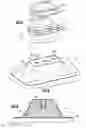
FIG. 3A shows a first step in assembling the attachment.
FIG. 3B is a cross-sectional view through the FIG. 3A structure.
FIG. 4 shows a subsequent step.
FIG. 5 shows another subsequent step.
FIG. 6 is a cross-sectional view through an assembly.
DETAILED DESCRIPTION
A gas turbine engine 10, such as a turbofan gas turbine engine, circumferentially disposed about an engine centerline, or axial centerline axis 12 is shown in FIG. 1A. The engine 10 includes a fan 14, compressor sections 15 and 16, a combustion section 18 and a turbine 19. A fan case 20 surrounds the fan 14. As is well known in the art, air from fan 14 is compressed in the compressor 15/16, mixed with fuel and burned in the combustion section 18 and expanded in turbine 19. The turbine 19 includes rotors 122 and 124, which rotate in response to the expansion. The turbine 19 comprises alternating rows of rotary airfoils or blades 126 and static airfoils or vanes 128. In fact, this view is quite schematic, and blades 126 and vanes 128 are actually removable. It should be understood that this view is included simply to provide a basic understanding of the sections in a gas turbine engine, and not to limit the invention. This invention extends to all types of turbine engines for all types of applications.
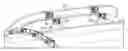
A composite fan case 20 is illustrated in FIG. 1B. The fan case 20 is part of a gas turbine engine, and includes the fan rotor (see FIG. 1A) delivering air downstream towards the compressor.
Threaded bolt attachments 22 are mounted on the outer surface of the fan case 20, in a manner to be described below. A component 24 is attached to the attachments 22, such as through pins 26 mounted at a bracket 28. The component 24 is shown as a holding bracket for a fluid tube. Any number of other components, and types of mountings may benefit from the present invention. The bracket 28 is threadably attached, such as by bolts 29 (see FIG. 1C), to the attachment 22.
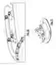
FIG. 2A shows a detail of the attachment 22, which includes a molded conical “bathtub” or boss which may be formed of a composite material 30. Of course, the bathtub or boss may be any number of different shapes including rectangular, square, oval, etc. Metallic inserts 32 are embedded within the composite material 30. A combination of fiberglass plies and adhesive 34 are attached to the outer surface of the composite material 30. Another combination of adhesive and fiberglass plies is formed on an inner surface of the composite material 30. This combination will be attached to the outer peripheral surface of the composite fan case 20, as will be described below. While fiberglass plies are disclosed, it should be understood that other fiber reinforced plies, such as carbon fiber reinforced plies, would come within the scope of this invention.
The insert 32 has flat ends 40 and 42, which will prevent rotation within the composite material 30. The other ends 46 and 48 are generally conical. An extending cylindrical portion 44 extends upwardly to a hole 50, which will receive a threaded insert, as will be explained below. Any number of other anti-rotation features can be utilized, such as any number of flat surfaces from one to any higher number.
FIG. 2C shows that there are two of the inserts 32 received within the composite material 30. The conical portion 46 faces a short circular end 54, while the composite material 30 has elongated sides 56. Flat ends 40 and 42 of insert 32 face these sides 56. Of course, the invention extends to a single insert.
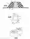
As shown in FIG. 3A, in assembling the attachment 22, the inserts 32 are initially inserted into openings 60 within pre-molded composite material 30. They could additionally be molded within the material 30. An adhesive may be placed on the metallic insert, to secure the metallic insert within the opening 60. Weight reduction or strengthening opening 62 (see FIG. 3B) may be formed within the composite material 30, as desired.
FIG. 4 shows a subsequent step, wherein an adhesive layer, plurality of fiberglass plies, and an outer adhesive 36 are all attached to the composite fan case 20 at a bottom of the composite material 30. The upper combination includes plurality plies of fiberglass 34, with an adhesive layer 36 attached to the outer surface of the composite material 30.
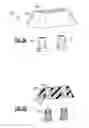
Then, as shown in FIG. 5, the attachment 22 then has holes 80 drilled through the outer fiberglass and adhesive combination 34 to align with holes 50, and which then receives inserts 82 which are threaded.
A helical insert or key-lock insert may be utilized as the inserts 82. Examples of brand names would be Helicoil™ or Keensert™. Each of these inserts is threaded into the holes 50. In fact, the holes 50 can be formed with threads to receive the inserts. The point of the insert is generally to provide a breaking point which will break away from the attachment 22 prior to the attachment 22 breaking away from the fan case 20.
When the combined attachment 22 is placed on fan case 20, it is then heated and the fiberglass and adhesive cures, forming to the outer surface of the fan case 20, and is securely fastened.
FIG. 6 shows a cross-section, with the threaded insert 82 received within the insert 32. Openings 62 are formed on each side of the insert 32. As can be appreciated from FIG. 6, the upper combination 34 extends beyond the edges of the boss, such that there is an overlap area 100 where the upper combination and the lower combination are directly in contact.
In a sense, the upper ply combination captures the composite material 30 and the insert 32, and holds it on the fan case. The underlying fiber reinforced ply and adhesive combination 38 holds the combination against the fan case. The areas beyond the material 30 where the upper and lower plies are in contact form a strong bond.
To attach the structure to the fan case, the plies, such as seen for example in FIG. 2A, may be placed on the outer surface of a fan case. A vacuum may be applied, and the material heated, such as to about 250° F. (121° C.). An oven may be utilized to provide this heating. In this manner, the fiber reinforced plies and adhesive cure on the outer surface, and should not break away.
In embodiments, the upper adhesive 36 and fiberglass combination 34 includes three plies of fiberglass with a single ply of adhesive in contact with the boss. The lower adhesive and fiberglass combination 36 may include a ply of adhesive 26, three plies of fiberglass 34, and then a ply of adhesive 36. Also, in embodiments, the boss composite material 30 may be injection molded plastic, SMC, or some other filled epoxy. Of course, other materials may be utilized, and other arrangements of the adhesive and fiberglass can also be utilized.
Although embodiments of this invention have been disclosed, a worker of ordinary skill in this art would recognize that certain modifications would come within the scope of this invention. For that reason, the following claims should be studied to determine the true scope and content of this invention.
Claims
What is claimed is:1. A composite fan case comprising:
a composite fan case body having an outer surface;
at least one bolt attachment attached to said outer surface of said fan case body, said bolt attachment including an internal composite boss having at least one metallic insert, said metallic insert being threaded, and said boss being attached to said outer surface of said body with a combination of at least one fiber reinforced ply and adhesive; and
an accessory attached to at least one said bolt attachment.
2. The composite fan case as set forth in claim 1, wherein at least one of said attachments are attached to the outer surface of said body, and each receives threaded fasteners to attach the accessory to the outer surface.
3. The composite fan case as set forth in claim 1, wherein said boss has a plurality of said inserts.
4. The composite fan case as set forth in claim 3, wherein each of said inserts receives a threaded insert.
5. The composite fan case as set forth in claim 1, wherein a combination of adhesive and fiber reinforced plies is applied to a surface of said boss remote from the outer surface of said fan case.
6. The composite fan case as set forth in claim 5, wherein said combination of fiberglass and adhesive which attaches said boss to said body, and said combination of adhesive and fiberglass plies applied to the surface of said boss remote from the outer surface of said fan case each extend beyond said boss, and are in contact with each other at a location beyond said boss.
7. The composite fan case as set forth in claim 1, wherein said insert includes conical surfaces on opposed circumferential ends of a threaded opening, and at least one flat side to prevent rotation of the insert within the boss.
8. The composite fan case as set forth in claim 7, wherein there is a plurality of opposed flat sides to provide anti-rotation.
9. The composite fan case as set forth in claim 1, wherein said fiber reinforced ply is a fiberglass ply.
10. A bolt attachment for being attached to an outer surface of a composite fan case in a gas turbine engine comprising:
a composite boss receiving a pair of metallic inserts, each of said metallic inserts including a threaded opening extending to an outer face of the boss;
an inner face adhesive and fiber reinforced ply combination is at an inner face of said boss, remote from the outer face, and said inner face adhesive and fiberglass combination for attachment to a composite fan case; and
an outer face adhesive and fiber reinforced ply combination attached to the outer face of said boss, with a hole through the outer face adhesive and fiber reinforced ply combination to provide connection to the threaded opening in each metallic insert.
11. The bolt attachment as set forth in claim 10, wherein each of said metallic inserts receives a threaded insert to provide the threaded bore.
12. The bolt attachment as set forth in claim 10, wherein each of said inserts include conical surfaces on opposed circumferential ends of the threaded opening, and at least one flat side to prevent rotation of the insert within the boss.
13. The bolt attachment as set forth in claim 10, wherein said inner face combination, which attaches said boss to said body, and said outer face combination each extend beyond said boss, and are in contact with each other at a location beyond said boss.
14. The bolt attachment as set forth in claim 10, wherein said fiber reinforced ply is a fiberglass ply.
15. A method of attaching a bolt attachment to a composite fan case in a gas turbine engine comprising the steps of:
placing a fiber reinforced ply and adhesive combination at an inner side of a boss, the boss receiving a pair of metallic inserts, each of said metallic inserts including an internally threaded opening;
attaching the bolt attachment to the composite fan case by heating and curing the fiberglass and adhesive combination.
16. The method as set forth in claim 15, wherein each of said metallic inserts receives a threaded insert to provide the threaded opening.
17. The method as set forth in claim 16, including the step of placing a combination of adhesive and fiber reinforced ply on a surface of said composite boss remote from the outer surface of said fan case.
18. The method as set forth in claim 17, wherein said combination of adhesive and fiber reinforced ply on a surface of said composite boss remote from the outer surface extends beyond the boss, and has a portion in contact with said fiber reinforced ply and adhesive combination that is placed at the inner side of said boss.
19. The method as set forth in claim 15, wherein an accessory is attached to the threaded opening.
20. The method as set forth in claim 19, wherein a single accessory is attached to bolts of said metallic inserts by threaded fasteners.
Images & Drawings included:

Sources:
- United States Patent and Trademark Office - verify current appl. status at the USPTO↗
Recent applications in this class:
- » 20250230758 2025-07-17
OFFSHORE STEAM TURBINE GENERATOR UNIT AND INSTALLING METHOD - » 20250075639 2025-03-06
DUCTING ARRANGEMENT FOR A GAS TURBINE ENGINE - » 20240392698 2024-11-28
GAS TURBINE ENGINE SUPPORT STRUCTURE WITH INTERNAL LATTICE - » 20240384669 2024-11-21
TOOL FOR ALIGNMENT OF SEAL SEGMENTS - » 20240352874 2024-10-24
ROTATING-MACHINE CASING SUPPORT STRUCTURE AND ROTATING MACHINE - » 20240295179 2024-09-05
GASKET FOR TURBINE ENGINE AND TURBINE MOUNT ASSEMBLY - » 20240287917 2024-08-29
Aircraft turbine engine assembly comprising a support for equipment - » 20240175377 2024-05-30
Offshore steam turbine generator unit and installing method - » 20240141805 2024-05-02
Gas turbine engine support structure with internal lattice - » 20240117757 2024-04-11
TURBOMACHINERY INSTALLATION FOR AN OFFSHORE PLATFORM
Recent applications for this Assignee:
- » 20210131352 2021-05-06
Methods and systems for a modulated bleed valve - » 20180375008 2018-12-27
Method of forming electrodes on electrocaloric film - » 20180348087 2018-12-06
Parametric trending architecture concept and design - » 20180238268 2018-08-23
Composite wear pad for exhaust nozzle - » 20180159366 2018-06-07
Intra-microgrid communication architecture - » 20180066532 2018-03-08
Flow directing cover for engine component - » 20180038231 2018-02-08
Cooling hole with enhanced flow attachment - » 20180036918 2018-02-08
Media containment for iso-grid structure forming - » 20180003082 2018-01-04
Multiple reservoir lubrication system - » 20170343011 2017-11-30
System for an improved stator assembly