LENS SYSTEM WITH REDUCED LENGTH AND HIGH RESOLUTION
US20130100541A1
2013-04-25
13/494,033
2012-06-12
Abstract:
A lens system includes, in this order from the object side to the image side of the lens system, a first lens group and a second lens group. The first lens group includes, in this order from the object side to the image side of the lens system, a first lens of negative refractive power and a second lens of positive refractive power. The second lens group includes, in this order from the object side to the image side of the lens system, a third lens of negative refractive power, a fourth lens positive refractive power, and a fifth lens of negative or positive refractive power. The lens system satisfies the following condition formula: 0.3<fF/fB<1.85, wherein fF, fB are the effective focal lengths of the first and second lens groups, respectively.
Inventors:
- FANG-YING PENG 30 🇹🇼 Tu-Cheng, Taiwan
- HAI-JO HUANG 31 🇹🇼 Tu-Cheng, Taiwan
- SHENG-AN WANG 35 🇹🇼 Tu-Cheng, Taiwan
- XIAO-NA LIU 26 🇨🇳 Shenzhen, China
- AN-TZE LEE 14 🇹🇼 Tu-Cheng, Taiwan
Assignee:
- HON HAI PRECISION INDUSTRY CO., LTD. 12,828 🇹🇼 Tu-Cheng, Taiwan
- HONG FU JIN PRECISION INDUSTRY (SHENZHEN) CO., LTD. 4,225 🇨🇳 Shenzhen City, China
Interested in similar patents?
Get notified when new applications in this technology area are published.
Classification:
G02B13/04 » CPC main
Optical objectives specially designed for the purposes specified below Reversed telephoto objectives
G02B9/60 IPC
Optical objectives characterised both by the number of the components and their arrangements according to their sign, i.e. + or - having five components only
G02B13/18 IPC
Optical objectives specially designed for the purposes specified below with lenses having one or more non-spherical faces, e.g. for reducing geometrical aberration
Description
BACKGROUND
1. Technical Field
The present disclosure relates to lenses and, particularly, to a lens system which has a short overall length and a high resolution.
2. Description of Related Art
To efficiently control the aberrations of lens system, additional lenses and/or other optical elements are required, which increases the total length of the lens system.
BRIEF DESCRIPTION OF THE DRAWINGS
Many aspects of the present disclosure can be better understood with reference to the following drawings. The components in the drawings are not necessarily drawn to scale, the emphasis instead being placed upon clearly illustrating the principles of the present disclosure. Moreover, in the drawings, like reference numerals designate corresponding parts throughout the views.
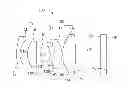
FIG. 1 is a schematic view of a lens system, according to an embodiment.
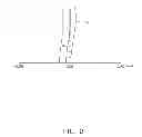
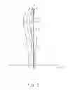
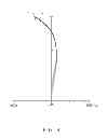
FIGS. 2-4 are graphs showing the spherical aberration, field curvature, and characteristics curves of the lens system of FIG. 1, respectively, according to a first embodiment.
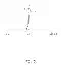
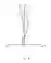
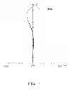
FIGS. 5-7 are graphs showing the spherical aberration, field curvature, and characteristics curves of the lens system of FIG. 1, respectively, according to a second embodiment.
DETAILED DESCRIPTION
Embodiments of the present disclosure will be described in detail with reference to the drawings.
FIG. 1, is a lens system 100, according to an embodiment. The lens system 100 includes, in this order from the object side to the image side of the lens system 100, a first lens group 10, an aperture stop 16, and a second lens group 20.
The first lens group 10 includes, in this order from the object side to the image side of the lens system 100, a first lens 11 of negative refractive power and a second lens 12 of positive refractive power. The second lens group 20 includes, in this order from the object side to the image side of the lens system 100, a third lens 13 of negative refractive power, a fourth lens 14 of positive refractive power, and a fifth lens 15 of negative or positive refractive power.
The first to fifth lenses 11-15 can be made from plastic, polymer, or glass, and, in this embodiment, are made of plastic to reduce cost.
The first, third, fifth lenses 11, 13, 15 are aspheric lenses and each has two aspheric surfaces. The aspherical surface is shaped according to the formula:
x = ch 2 1 + 1 - ( k + 1 ) c 2 h 2 + ∑ Aih i ,
where h is the height from the optical axis of the lens system 100 to a point on the aspherical surface, c is the vertex curvature, k is a conic constant, and Ai is the i-th order correction coefficient of the aspherical surface.
When capturing images, light rays enter the lens system 100, passing through the first to fifth lenses 11-15 in sequence, and then pass through a cover glass 17, and finally form optical images on an image plane 18.
The first lens 11 has an object-side surface 111 (i.e., adjacent to the object side of the lens system 100) and an image-side surface 112 (i.e., adjacent to the image side of the lens system 100). The second lens 12 has an object-side surface 121 and an image-side surface 122. The third lens 13 has an object-side surface 131 and an image-side surface 132. The fourth lens 14 has an object-side surface 141 and an image-side surface 142. The fifth lens 15 has an object-side surface 151 and an image-side surface 152. The cover glass 17 has a surface 171 facing the lens system 100 and a surface 172 facing away from the lens system 100.
The lens system 100 satisfies the following condition formula: 0.3<fF/fB<1.85, wherein fF, fB are the effective focal lengths of the first and second lens groups 10, 20, respectively.
By satisfying the above-mentioned condition formula, a short total overall length and a high resolution can be obtained in the lens system 100. In contrast, if the above-mentioned condition formula is not satisfied, the advantages of the lens system 100 can not be achieved.
To further enhance the resolution of the lens system 100, the lens system 100 further satisfies the following condition formula: 0.48<|f3/f4|<1.42, Wherein f3, f4 are the effective focal lengths of the third and fourth lenses 13, 14.
To efficiently correct lateral aberration occurring in the lens system 100, the lens system 100 further satisfies the condition formulas: 6<V2/V3<2.5 and 1.6<V4/V3<3.6, wherein V2-V4 are the Abbe numbers of light at the wavelength of 587.6 nm (d light) in the second to fourth lenses 12-14, respectively.
The lens system 100 satisfies Tables 1-3 in a first embodiment, where the following symbols are used:
- R: the curvature radius of each surface;
- D: the distance between each two adjacent surfaces along the optical axis of the lens system 100;
- Nd: the refractive index of d light in each lens or the cover glass 17; and
- Vd: the Abbe number of d light in each lens or the cover glass 17.
| TABLE 1 | ||||
| Surface | R (mm) | D (mm) | Nd | Vd |
| 111 | 6.651706 | 0.554 | 1.531 | 55.75 |
| 112 | 2.725919 | 1.136 | — | — |
| 121 | 3.187 | 1.417 | 1.596 | 39.22 |
| 122 | −386.787 | 0.728 | — | — |
| 16 | infinity | 1.398 | — | — |
| 131 | −1.700841 | 0.399 | 1.633 | 23.24 |
| 132 | −27.14757 | 0.18 | — | — |
| 141 | −40.641 | 1.213 | 1.596 | 39.22 |
| 142 | −3.253 | 0.099 | — | — |
| 151 | 3.871036 | 2.061 | 1.543 | 56.8 |
| 152 | −9.56112 | 3.93 | — | — |
| 171 | infinity | 0.8 | 1.517 | 64.17 |
| 172 | infinity | 0.1 | — | — |
| 18 | infinity | — | — | — |
| TABLE 2 | |
| Surface |
| 111 | 112 | 131 | 131 | 151 | 152 | |
| K | 0 | 0 | 0 | 0 | 0 | 0 |
| A4 | −0.00087045537 | −0.003541817 | 0.015395688 | −0.0048917803 | −0.0049368649 | 0.0065112019 |
| A6 | −0.00055282669 | −0.0011980595 | 0.0061424656 | 0.0014558243 | 0.00010350228 | −0.0007520526 |
| A8 | 5.9566058 × 10⁻⁵ | −7.6390736 × 10⁻⁵ | −0.0024374421 | 7.314689 × 10⁻⁶ | 2.0066664 × 10⁻⁵ | 0.00012344376 |
| A10 | −4.1986206 × 10⁻⁶ | 1.5904199 × 10⁻⁵ | 0.0021543881 | −1.959752 × 10⁻⁵ | −6.8223668 × 10⁻⁶ | −1.2918445 × 10⁻⁵ |
| A12 | 2.3583807 × 10⁻⁷ | −1.8179786 × 10⁻⁶ | 0.00021043091 | 9.9686161 × 10⁻⁷ | 4.8161694 × 10⁻⁷ | −8.475658 × 10⁻⁸ |
| A14 | −3.358259 × 10⁻⁹ | 2.3295355 × 10⁻⁷ | −0.00052830802 | −4.4291647 × 10⁻⁷ | −4.9522888 × 10⁻¹⁰ | 1.1230649 × 10⁻⁷ |
| A16 | −5.7695815 × 10⁻¹¹ | −3.7075028 × 10⁻⁸ | 0.00017401058 | 1.7441398 × 10⁻⁷ | −1.0637237 × 10⁻⁹ | −5.7837028 × 10⁻⁹ |
| TABLE 3 | ||
| fF | 10.324 | |
| fB | 5.728 | |
| f3 | −2.885 | |
| f4 | 5.867 | |
| V2 | 39.22 | |
| V3 | 23.24 | |
| V4 | 39.22 | |
| fF/fB | 1.802 | |
| |f3/f4| | 0.492 | |
| V2/V3 | 1.688 | |
| V4/V3 | 1.688 | |
In this embodiment, the effective focal length of the lens system 100 is about 5.323 mm, the filed of view is about 61 degrees, and the F number is about 2.4.
In FIG. 2, the curves a-c show the spherical aberration characteristics of light of the wavelengths 486 nm, 588 nm, 656 nm, respectively, in the lens system 100 of the first embodiment, which are controlled in a range of about −0.2 mm to about 0.2 mm. In FIG. 3, the curves A-C show the meridional (T curves) and sagittal (S curves) field curvatures of light of the wavelength 486 nm, 588 nm, 656 nm, respectively, in the lens system 100 of the first embodiment, which are controlled in a range of about −0.2% to about 0.2%. In FIG. 4, the curves L-N depict the distortion characteristics of light of the wavelengths 486 nm, 588 nm, 656 nm, respectively, in the lens system 100 of the first embodiment, which is controlled in a range of about −5% to about 5%.
The lens system 100 satisfies Tables 4-6 in a second embodiment.
| TABLE 4 | ||||
| Surface | R (mm) | D (mm) | Nd | Vd |
| 111 | 8.423295 | 0.554 | 1.531 | 55.75 |
| 112 | 2.201278 | 2.072 | — | — |
| 121 | 3.901 | 1.246 | 1.697 | 56.42 |
| 122 | −9.944 | 0.099 | — | — |
| 16 | infinity | 1.547 | — | |
| 131 | 7.89663 | 0.4 | 1.633 | 23.24 |
| 132 | 2.649324 | 0.385 | — | — |
| 141 | 6.657 | 2.818 | 1.497 | 81.61 |
| 142 | −3.04 | 1.4 | — | — |
| 151 | −28.94435 | 1.8 | 1.543 | 56.8 |
| 152 | 10.48121 | 0.94 | — | — |
| 171 | infinity | 0.8 | 1.517 | 64.17 |
| 172 | infinity | 0.1 | — | — |
| 18 | infinity | — | — | — |
| TABLE 5 | |
| Surface |
| 111 | 112 | 131 | |
| K | 0 | 0 | 0 |
| A4 | 0.0035852171 | 0.0019255609 | −0.02470804 |
| A6 | −0.0010634939 | −0.0024889945 | 0.0027564826 |
| A8 | 0.00010121061 | 0.00020788899 | −0.002261841 |
| A10 | 2.6358049 × 10⁻⁶ | −0.00012220043 | 0.00066508408 |
| A12 | −1.2490536 × 10⁻⁶ | 1.9474688 × 10⁻⁵ | −6.0769257 × 10⁻⁵ |
| A14 | −3.6022421 × 10⁻⁸ | −7.5105772 × 10⁻⁷ | −4.1177299 × 10⁻⁵ |
| A16 | 1.2380055 × 10⁻⁸ | −8.4917231 × 10⁻⁷ | 8.8464628 × 10⁻⁶ |
| Surface |
| 131 | 151 | 152 | |
| K | 0 | 0 | 0 |
| A4 | −0.022246257 | −0.019732317 | −0.020866794 |
| A6 | 0.0020097153 | −0.00019192699 | 1.1238266 × 10⁻⁵ |
| A8 | −0.00046837999 | −0.0001503506 | 4.7075407 × 10⁻⁵ |
| A10 | −1.0613336 × 10⁻⁵ | 0 | 0 |
| A12 | 2.7830166 × 10⁻⁵ | 0 | 0 |
| A14 | −7.20013 × 10⁻⁶ | −5.4053248 × 10⁻⁷ | −4.5456317 × 10⁻⁸ |
| A16 | 7.342059 × 10⁻⁷ | 4.870945 × 10⁻⁸ | 2.5272218 × 10⁻⁹ |
| TABLE 3 | ||
| fF | 6.418 | |
| fB | 19.629 | |
| f3 | −6.493 | |
| f4 | 4.648 | |
| V2 | 56.42 | |
| V3 | 23.24 | |
| V4 | 81.61 | |
| fF/fB | 0.327 | |
| |f3/f4| | 1.397 | |
| V2/V3 | 2.428 | |
| V4/V3 | 3.512 | |
In this embodiment, the effective focal length of the lens system 100 is about 5.312 mm, the filed of view is about 59 degrees, and the F number is about 2.4.
In FIG. 5, the curves a-c show the spherical aberration characteristics of light of the wavelengths 486 nm, 588 nm, 656 nm, respectively, in the lens system 100 of the second embodiment, which are controlled in a range of about −0.2 mm to about 0.2 mm. In FIG. 6, the curves A-C show the meridional (T curves) and sagittal (S curves) field curvatures of light of the wavelength 486 nm, 588 nm, 656 nm, respectively, in the lens system 100 of the second embodiment, controlled in a range of about −0.2% to about 0.2%. In FIG. 7, the curves L-N depict the distortion characteristics of light of the wavelengths 486 nm, 588 nm, 656 nm, respectively, in the lens system 100 of the second embodiment, which is controlled in a range of about −5% to about 5%.
It will be understood that the above particular embodiments are shown and described by way of illustration only. The principles and the features of the present disclosure may be employed in various and numerous embodiment thereof without departing from the scope of the disclosure as claimed. The above-described embodiments illustrate the possible scope of the disclosure but do not restrict the scope of the disclosure.
Claims
What is claimed is:1. A lens system, comprising, in this order from the object side to the image side of the lens system, a first lens group and a second lens group, the first lens group comprising, in this order from the object side to the image side of the lens system, a first lens of negative refractive power and a second lens of positive refractive power; the second lens group comprising, in this order from the object side to the image side of the lens system, a third lens of negative refractive power, a fourth lens positive refractive power, and a fifth lens of negative or positive refractive power, wherein the lens system satisfies the following condition formula: 0.3<fF/fB<1.85, where fF, fB are the effective focal lengths of the first and second lens groups, respectively.
2. The lens system of claim 1, wherein the first to fifth lenses are made from a material selected from the group consisting of plastic, polymer, and glass.
3. The lens system of claim 1, wherein the first, third, fifth lenses are aspheric lenses and each has two aspheric surfaces.
4. Then lens system of claim 1, further comprising an aperture stop interposed between the first and second lens groups.
5. The lens system of claim 1, wherein the lens system further satisfies the following condition formula: 0.48<|f3/f4|<1.42, Wherein f3, f4 are the effective focal lengths of the third and fourth lenses, respectively.
6. The lens system of claim 1, wherein the lens system further satisfies the condition formulas: 6<V2/V3<2.5 and 1.6<V4/V3<3.6, wherein V2-V4 are the Abbe numbers of light at the wavelength of 587.6 nm in the second to fourth lenses, respectively.
Images & Drawings included:

Sources:
- United States Patent and Trademark Office - verify current appl. status at the USPTO↗
Similar patent applications:
Recent applications in this class:
- » 20130250166 2013-09-26
High-speed wide-angle lens construction - » 20130250039 2013-09-26
Wide-angle depth imaging lens construction - » 20130141804 2013-06-06
Projection lens system with long back focal length - » 20130100544 2013-04-25
Projection lens system with high resolution and compact size - » 20130094100 2013-04-18
Lens system - » 20130077157 2013-03-28
Ultra compact inverse telephoto optical system for use in the IR spectrum - » 20130063829 2013-03-14
Fixed focus lens system - » 20130063648 2013-03-14
Optical system and optical apparatus using the same - » 20130057972 2013-03-07
Single focus lens system and photographing apparatus including the same
Recent applications for this Assignee:
- » 20140233961 2014-08-21
Optical communication module including optical-electrical signal converters and optical signal generators - » 20140083669 2014-03-27
HEAT SINK - » 20140083669 2014-03-27
HEAT SINK - » 20140063746 2014-03-06
Electronic device with heat dissipation assembly - » 20140061224 2014-03-06
AUTOMATIC VENDING MACHINE - » 20140060914 2014-03-06
Enclosure with shield apparatus - » 20140058727 2014-02-27
MULTIMEDIA RECORDING SYSTEM AND METHOD - » 20140055955 2014-02-27
Fastener - » 20140055322 2014-02-27
DISPLAY SYSTEM AND HEAD-MOUNTED DISPLAY APPARATUS - » 20140054439 2014-02-27
CONTAINER DATA CENTER WITH SUPPORTING APPARATUS