Zoom lens system
US20130135752A1
2013-05-30
13/340,695
2011-12-30
✅ Patent granted
US 8,570,664 B2
2013-10-29
-
-
William Choi
Altis & Wispro Law Group, Inc.
2032-03-24
Abstract:
A zoom lens system includes a first lens group of negative refractive power, a second lens group of positive refractive power and a third lens group of positive refractive power. The zoom lens system satisfies the following condition formulas: 0.78<|f2/f1|<0.91, and 0.72<L2/fT<0.87, where f1 represents an effective focal length of the first lens group, f2 represents an effective focal length of the second lens group, L2 is a displacement of the second lens group when the zoom lens system varies from a wide-angle state to a telephoto state, and fT represents an effective focal length of the zoom lens system which is in the telephoto state.
Inventors:
- FANG-YING PENG 30 🇹🇼 Tu-Cheng, Taiwan
- HAI-JO HUANG 31 🇹🇼 Tu-Cheng, Taiwan
- SHENG-AN WANG 35 🇹🇼 Tu-Cheng, Taiwan
- XIAO-NA LIU 26 🇨🇳 Shenzhen, China
- AN-TZE LEE 14 🇹🇼 Tu-Cheng, Taiwan
- AN-TZE LEE 13 🇹🇼 New Taipei, Taiwan
- SHENG-AN WANG 13 🇹🇼 New Taipei, Taiwan
- Xiao-Na Liu 27 🇨🇳 Guangdong, China
- Fang-Ying Peng 12 🇹🇼 New Taipei, Taiwan
- Hai-Jo Huang 12 🇹🇼 New Taipei, Taiwan
Assignee:
- HON HAI PRECISION INDUSTRY CO., LTD. 12,833 🇹🇼 Tu-Cheng, Taiwan
- HONG FU JIN PRECISION INDUSTRY (SHENZHEN) CO., LTD. 4,225 🇨🇳 Shenzhen City, China
- HONG FU JIN PRECISION INDUSTRY (ShenZhen) CO., LTD. 2,585 🇨🇳 Shenzhen, China
- HONG HAI PRECISION INDUSTRY CO., LTD. 6 🇹🇼 New Taipei, Taiwan
Applicant:
Interested in similar patents?
Get notified when new applications in this technology area are published.
Classification:
G02B15/14 IPC
Optical objectives with means for varying the magnification by axial movement of one or more lenses or groups of lenses relative to the image plane for continuously varying the equivalent focal length of the objective
G02B15/143507 » CPC main
Optical objectives with means for varying the magnification by axial movement of one or more lenses or groups of lenses relative to the image plane for continuously varying the equivalent focal length of the objective having three groups only the first group being negative arranged -++
Description
BACKGROUND
1. Technical Field
The present disclosure relates to lenses and, particularly, to a zoom lens system which has a high zoom ratio, a reduced total length, and a high resolution.
2. Description of Related Art
To obtain small camera modules which provide a high quality image over a large object distance range, a zoom lens system having a high zoom ratio, a short total length, and a high resolution is desired.
BRIEF DESCRIPTION OF THE DRAWINGS
Many aspects of the present disclosure can be better understood with reference to the following drawings. The components in the drawings are not necessarily drawn to scale, the emphasis instead being placed upon clearly illustrating the principles of the present disclosure. Moreover, in the drawings, like reference numerals designate corresponding parts throughout the views.
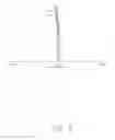
FIG. 1 is a schematic view of a zoom lens system, according to an embodiment.
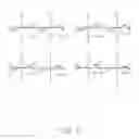
FIGS. 2-5 are graphs showing the transverse aberration, spherical aberration, field curvature, and distortion occurring in the zoom lens system of FIG. 1 in a wide-angle state.
FIGS. 6-9 are graphs showing the transverse aberration, spherical aberration, and field curvature, and distortion occurring in the zoom lens system of FIG. 1, in a telephoto state.
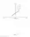
FIG. 10 is a schematic view of a zoom lens system, according to another embodiment.
FIGS. 11-14 are graphs showing the transverse aberration, spherical aberration, field curvature, and distortion occurring in the zoom lens system of FIG. 8 in a wide-angle state.
FIGS. 12-18 are graphs showing the transverse aberration, spherical aberration, and field curvature, and distortion occurring in the zoom lens system of FIG. 8 in a telephoto state.
DETAILED DESCRIPTION
Embodiments of the present disclosure will be described in detail with reference to the drawings.
Referring to FIG. 1, a zoom lens system 10, according to an embodiment, includes, in an order from its object-side to its image-side, a first lens group 100 of negative refractive power, a second lens group 200 of positive refractive power, and a third lens group 300 of positive refractive power. The zoom lens system 10 satisfies the following condition formulas: 0.78<|f2/f1|<0.91 and 0.72<L2/fT<0.87, where f1 represents the effective focal length of the first lens group 100, f2 represents the effective focal length of the second lens group 200, L2 is the displacement of the second lens group 200 when the zoom lens system 10 is changed from a wide-angle state to a telephoto state, and fT represents the effective focal length of the zoom lens system 10 which is in a telephoto state.
By satisfying the above-listed condition formulas, the effective focal length of the zoom lens system 10 can be varied over a large range by changing a distance between the first lens group 100 and the second lens group 200, so obtaining a relatively high zoom ratio. In contrast, if the above-listed condition formulas are not satisfied, the advantages of a high zoom ratio, a short total overall length, or/and the high resolution of the zoom lens system 10 cannot be achieved.
For example, if the condition formula: 0.78<|f2/f1|<0.91 is not satisfied, then (1) the spherical aberration and color aberration occurring in the zoom lens system 10 in both the wide-angle and the telephoto states cannot be effectively controlled if the effective focal length of the second lens group 200 is too short, thus degrading the resolution of the zoom lens system 10; and (2) the distortion occurring in the zoom lens system 10 in the wide-angle state cannot be effectively controlled if the effective focal length of the first lens group 100 is too short, thus again degrading the resolution of the zoom lens system 10, and (3) the total length of the zoom lens system 10 in the wide-angle state cannot be effectively controlled if the effective focal length of the first lens group 100 is too long, thus increasing the total overall length of the zoom lens system 10.
If the condition formula: 0.72<L2/fT<0.87 is not satisfied, then the total overall length of the zoom lens system 10 cannot be controlled if the displacement is too large, or the spherical aberration and color aberration occurring in the zoom lens system 10 in the wide-angle state cannot be controlled if the displacement is too small.
When capturing images, light rays enter the zoom lens system 10, passing through the first lens group 100, the second lens group 200, and the third lens group 300 in sequence, and then pass through a filter 20 and a cover glass 30, and finally form images on an image plane IMG. During the capture, the distance between the first lens group 100 and the second lens group 200 can be adjusted to obtain a suitable effective focal length of the zoom lens system 10. After the effective focal length of the zoom lens system 10 has been fixed, the third lens group 300 can be moved along the optical axis of the zoom lens system 10 to focus the zoom lens system 10.
The first lens group 100 includes, in the order from the object-side to the image-side of the zoom lens system 10, a first lens 102 of negative refractive power and a second lens 104 of positive refractive power. The second lens group 200 includes, in the order from the object-side to the image-side of the zoom lens system 10, a third lens 202 of positive refractive power, a fourth lens 204 of positive refractive power, a fifth lens 206 of negative refractive power, and a sixth lens 208 of negative refractive power. The fourth lens 204 and the fifth lens 206 are combined. The third lens group 300 includes a seventh lens 302 of positive power.
The zoom lens system 10 further satisfies the following condition formula: 1.75<V1/V2<2.45, where V1 and V2 are the Abbe numbers of the first and second lenses 102 and 104 in light at the wavelength of 587.6 nm (d light) respectively. In this way, any color aberration occurring in the zoom lens system 10 can be further restricted.
The zoom lens system 10 also satisfies the condition formula: 0.27<f2/f3<0.5, where f3 represents the effective focal length of the third lens group 300. In this way, a focusing sensitivity of the third lens group 300 can be suitably adjusted.
The third lens 202 includes at least one aspherical surface. As such, any spherical aberration and color aberration occurring in the zoom lens system 10 in both the wide-angle and telephoto states can be restricted. The sixth lens 208 is a plastic lens to reduce the costs of the zoom lens system 10.
The zoom lens system 10 includes an aperture stop 400 interposed between the second lens group 200 and the third lens group 300. The zoom lens system 10 includes, in the order from the object-side to the image-side, surfaces S1-S14. The filter 20 includes, in the order from the object-side to the image-side, surfaces S15-S16. The cover glass 30 includes, in the order from the object-side to the image-side, surfaces S17-S18.
The zoom lens system 10 satisfies Table 1, where the following symbols are used:
F: the effective focal length of the zoom lens system 10;
FNo: the focal ratio (F number);
2ω: the field angle;
R: the curvature radius of each surface;
D: the distance between each two adjacent surfaces along the optical axis of the zoom lens system 10;
Nd: the refractive index of each lens or the filter 20 or the cover glass 30 in d light; and
Vd: the Abbe number of each lens or the filter 20 or the cover glass 30 in d light.
| TABLE 1 | |||||
| Surface | R (mm) | D (mm) | ND | VD | |
| S1 | −243.0664 | 0.7 | 1.821 | 42.71 | |
| S2 | 6.986198 | 1.635 | — | — | |
| S3 | 9.795 | 1.949 | 1.946 | 17.98 | |
| S4 | 17.098 | D4 | — | — | |
| S5 | 9.080511 | 1.315 | 1.801 | 45.45 | |
| S6 | 45.79786 | 0.1 | — | — | |
| S7 | 6.204 | 1.286 | 1.741 | 52.6 | |
| S8 | 30.492 | 1.132 | 1.847 | 23.62 | |
| S9 | 4.838 | 1.073 | — | — | |
| S10 | −66.5612 | 0.841 | 1.531 | 55.75 | |
| S11 | −10.9801 | 0.5 | — | — | |
| S12 | Infinity | D12 | — | — | |
| S13 | −700.586 | 1.152 | 1.785 | 25.72 | |
| S14 | −17.294 | D14 | — | — | |
| S15 | Infinity | 0.3 | 1.52 | 64.2 | |
| S16 | Infinity | 0.3 | — | — | |
| S17 | Infinity | 0.5 | 1.52 | 64.2 | |
| S18 | Infinity | 0.4 | — | ||
| IMG | Infinity | — | — | — | |
The aspherical surface is shaped according to the formula:
x = ch 2 1 + 1 - ( k + 1 ) c 2 h 2 + ∑ Aih i ,
where h is the height from the optical axis of the zoom lens system 10 to a point of the aspherical surface, c is the vertex curvature, k is a conic constant, and Ai is the i-th order correction coefficient of the aspherical surface.
The zoom lens system 10 also satisfies Tables 2-4:
| TABLE 2 | |||
| S1 | S2 | S5 | |
| K | 499.686 | 0.06879327 | 0.5368633 |
| A4 | −9.8703956e-005 | −0.00022425152 | −0.00034048197 |
| A6 | 3.8201302e-006 | −3.9956898e-006 | 2.0874412e-006 |
| A8 | −2.6961178e-008 | 3.4276174e-007 | 3.8276242e-008 |
| A10 | −1.7656108e-010 | −1.5552525e-008 | −5.9444241e-008 |
| A12 | 4.385518e-012 | 2.1253295e-010 | −2.8580116e-010 |
| A14 | −5.0093241e-014 | 1.5377698e-012 | 5.5525497e-010 |
| A16 | 4.4099635e-016 | −7.7311868e-014 | −2.9974179e-011 |
| TABLE 3 | |||
| S6 | S10 | S11 | |
| K | 126.4003 | −1318.043 | −2.423973 |
| A4 | −0.00039669862 | −0.0014985306 | −0.00036451564 |
| A6 | 4.7406796e-006 | 0.00013064897 | −4.5827646e-006 |
| A8 | −4.2054543e-007 | −9.8508789e-006 | −4.5230724e-006 |
| A10 | −4.7513838e-008 | 2.2182242e-008 | 2.6670809e-006 |
| A22 | 8.2636708e-010 | 2.05636e-007 | 1.2611351e-009 |
| A14 | 2.5839402e-010 | 2.6891843e-008 | −2.629116e-008 |
| A16 | −2.4846792e-011 | −5.1058739e-009 | 1.0645869e-009 |
| TABLE 4 | |||||
| F | FNo | 2ω | D4 (mm) | D12 (mm) | D14 (mm) |
| 5.046 | 3.45 | 80 | 21.87 | 6.192 | 2.015 |
| 17.81 | 5.15 | 24.67 | 2.763 | 17.899 | 2.55 |
| 28.76 | 6.15 | 15.43 | 0.404 | 28.389 | 1.01 |
The values of relevant parameters and the condition formulas are listed in Table 5:
| TABLE 5 | ||
| parameter/condition | ||
| formula | value | |
| f1 | −13.92 | |
| f2 | 11.17 | |
| f3 | 22.58 | |
| fT | 28.76 | |
| L2 | 21.19 | |
| V1 | 42.706 | |
| V2 | 17.984. | |
| |f2/f1| | 0.802 | |
| L2/fT | 0.737 | |
| V1/V2 | 2.374 | |
| f2/f3 | 0.495 | |
In FIGS. 2 and 6, the graphs, from top left to bottom right, show the transverse aberration characteristics of ¼ field, ½ field, ¾ field, and the whole field, and, in each graph, the curves correspond to lights of the wavelengths 486 nm, 588 nm, and 656 nm. In FIGS. 3-5 and 7-9, the curves a1, b1, and c1 show the spherical aberration characteristics of lights of the wavelengths 486 nm, 588 nm, and 656 nm in the zoom lens system 10. The curves at, as, bt, bs, ct, and cs show the meridional and sagittal field curvatures of lights of the wavelengths 486 nm, 588 nm, and 656 nm in the zoom lens system 10. The curves a2, b2, and c2 depict the distortion characteristics of lights of the wavelengths 486 nm, 588 nm, and 656 nm in the zoom lens system 10. As shown in FIGS. 2-9, various aberrations occurring in the zoom lens system 10 are controlled, increasing the resolution of the zoom lens system 10.
Referring to FIG. 10, a zoom lens system 90, according to another embodiment, is substantially similar to the zoom lens system 10 but satisfies Tables 6-10 in this way.
| TABLE 6 | ||||
| Surface | R (mm) | D (mm) | ND | VD |
| S1 | −125.0187 | 0.7 | 1.821 | 42.71 |
| S2 | 6.560378 | 1.756 | − | − |
| S3 | 9.652 | 2.396 | 1.847 | 23.78 |
| S4 | 19.269 | D4 | − | − |
| S5 | 9.281855 | 1.295 | 1.801 | 45.45 |
| S6 | 46.52185 | 0.1 | − | − |
| S7 | 6.521 | 1.164 | 1.741 | 52.6 |
| S8 | 14.319 | 1.09 | 1.847 | 23.78 |
| S9 | 4.934 | 1.015 | − | − |
| S10 | −86.41501 | 0.893 | 1.531 | 55.75 |
| S11 | −10.28002 | 0.5 | − | − |
| S12 | Infinity | D12 | − | − |
| S13 | −67.317 | 0.95 | 1.773 | 49.57 |
| S14 | −21.019 | D14 | − | − |
| S15 | Infinity | 0.3 | 1.52 | 64.2 |
| S16 | Infinity | 0.3 | − | − |
| S17 | Infinity | 0.5 | 1.52 | 64.2 |
| S18 | Infinity | 0.4 | − | − |
| IMG | Infinity | − | − | − |
| TABLE 7 | |||
| S1 | S2 | S5 | |
| k | −372.8928 | 0.02221197 | 0.3854655 |
| A4 | −1.4945826e-005 | −0.00015791223 | −0.0003820942 |
| A6 | 2.9255894e-006 | −5.2545975e-006 | 5.0598402e-007 |
| A8 | −4.2898424e-008 | 3.7082278e-007 | 1.8219305e-007 |
| A10 | −2.8073063e-010 | −1.7539774e-008 | −5.9434353e-008 |
| A12 | 6.5706444e-012 | 1.3271629e-010 | −5.8087949e-010 |
| A14 | 4.6730833e-015 | 1.6684308e-012 | 6.9393231e-010 |
| A16 | 1.1921464e-016 | −6.6473219e-014 | −3.504407e-011 |
| TABLE 8 | |||
| S6 | S10 | S11 | |
| k | 129.9844 | −5673.337 | −1.642425 |
| A4 | −0.00046802677 | −0.0016357099 | −0.00053388651 |
| A6 | 1.1075687e-005 | 0.0001708832 | 1.7964967e-005 |
| A8 | −5.5376959e-007 | −3.2200392e-006 | −5.8194269e-006 |
| A10 | −4.9126047e-008 | 1.2349572e-007 | 2.6425244e-006 |
| A12 | 3.0430274e-009 | 1.4236873e-007 | 4.9296363e-008 |
| A14 | 3.5814826e-010 | 1.9537233e-008 | −2.215772e-008 |
| A16 | −3.3612306e-011 | −3.0743549e-009 | 6.8878413e-010 |
| TABLE 9 | |||||
| F | FNo | 2ω | D4 (mm) | D12 (mm) | D14 (mm) |
| 5.033 | 3.45 | 80 | 21.38 | 6.051 | 3.077 |
| 17.82 | 5.15 | 24.67 | 3.223 | 18.94 | 2.921 |
| 28.78 | 6.15 | 15.43 | 0.3 | 29.224 | 4.6 |
| TABLE 10 | ||
| parameter/condition | ||
| formula | value | |
| f1 | −12.61 | |
| f2 | 11.31 | |
| f3 | 39.18 | |
| fT | 28.78 | |
| L2 | 24.696 | |
| V1 | 42.706 | |
| V2 | 23.784. | |
| |f2/f1| | 0.897 | |
| L2/fT | 0.858 | |
| V1/V2 | 1.796 | |
| f2/f3 | 0.288 | |
As shown in FIGS. 11-18, any aberrations occurring in the zoom lens system 90 are also controlled.
It will be understood that the above particular embodiments are shown and described by way of illustration only. The principles and the features of the present disclosure may be employed in various and numerous embodiment thereof without departing from the scope of the disclosure as claimed. The above-described embodiments illustrate the possible scope of the disclosure but do not restrict the scope of the disclosure.
Claims
What is claimed is:1. A zoom lens system, in order from an object-side to an image-side thereof, comprising:
a first lens group of negative refractive power;
a second lens group of positive refractive power; and
a third lens group of positive refractive power;
the zoom lens system satisfying the following condition formulas:
0.78<|f2/f1|<0.91, and
0.72<L2/fT<0.87,
where f1 represents an effective focal length of the first lens group, f2 represents an effective focal length of the second lens group, L2 is a displacement of the second lens group when the zoom lens system varies from a wide-angle state to a telephoto state, and fT represents an effective focal length of the zoom lens system which is in the telephoto state.
2. The zoom lens system of claim 1, wherein the first lens group comprises, in the order from the object-side to the image-side of the zoom lens system, a first lens of negative refractive power and a second lens of positive refractive power.
3. The zoom lens system of claim 2, wherein the zoom lens system satisfies the following condition formula: 1.75<V1/V2<2.45, where V1, V2 are Abbe numbers of the first lens and the second lens in d light, respectively.
4. The zoom lens system of claim 1, wherein the second lens group comprises, in the order from the object-side to the image-side of the zoom lens system, a third lens of positive refractive power, a fourth lens of positive refractive power, a fifth lens of negative refractive power, and a sixth lens of negative refractive power.
5. The zoom lens system of claim 4, wherein the third lens comprises at least one aspherical surface.
6. The zoom lens system of claim 4, wherein the sixth lens is a plastic lens.
7. The zoom lens system of claim 4, wherein the fourth lens and the fifth lens are combined together.
8. The zoom lens system of claim 1, wherein the third lens group comprises a seventh lens of positive refractive power.
9. The zoom lens system of claim 1, wherein the zoom lens system satisfies the following condition formula: 0.28<f2/f3<0.5, where f3 represents an effective focal length of the third lens group.
10. The zoom lens system of claim 1, further comprising an aperture stop positioned between the second lens group and the third lens group.
Images & Drawings included:


Sources:
- United States Patent and Trademark Office - verify current appl. status at the USPTO↗
Similar patent applications:
- » 20170242227
Zoom lens system, interchangeable lens device and camera system with zoom lens system, and imaging apparatus with zoom lens system - » 20090161229
Zoom lens system, optical device with zoom lens system, and method of manufacturing zoom lens system - » 20110096409
Zoom lens system, optical device with zoom lens system, and method of manufacturing zoom lens system - » 20110141575
Zoom lens system, optical apparatus equipped with zoom lens system and method for zooming zoom lens system - » 20090147376
Zoom lens system, optical device with zoom lens system, and method of manufacturing zoom lens system - » 20090244720
Zoom lens system, optical device with the zoom lens system, and method of manufacturing the zoom lens system - » 20130120854
Zoom lens system, optical device with the zoom lens system, and method of manufacturing the zoom lens system - » 20110228406
Zoom lens system, optical device with the zoom lens system, and method of manufacturing the zoom lens system - » 20080198476
Zoom lens system and camera including zoom lens system - » 20180326909
Zoom lens system, imaging device having zoom lens system, and vehicle having imaging device
Recent applications in this class:
- » 20250244565 2025-07-31
LENS ASSEMBLY AND ELECTRONIC DEVICE COMPRISING SAME - » 20240264416 2024-08-08
ZOOM LENS AND IMAGING APPARATUS - » 20240210667 2024-06-27
Zoom optical system - » 20220236544 2022-07-28
Zoom lens and imaging apparatus - » 20220113521 2022-04-14
Zoom lens and image pickup apparatus - » 20220091400 2022-03-24
VARIABLE MAGNIFICATION OPTICAL SYSTEM, OPTICAL EQUIPMENT, AND METHOD FOR PRODUCING VARIABLE MAGNIFICATION OPTICAL SYSTEM - » 20220075163 2022-03-10
Image capturing lens system, image capturing unit and electronic device - » 20210294082 2021-09-23
Zoom lens and imaging apparatus - » 20210223523 2021-07-22
Zoom lens system and imaging apparatus - » 20210181488 2021-06-17
WIDE-ANGLE OPTICAL SYSTEM AND IMAGE PICKUP APPARATUS USING THE SAME
Recent applications for this Assignee:
- » 20220067430 2022-03-03
Image data classification method, computer device, and readable storage medium - » 20210325770 2021-10-21
Light-emitting device and projector using the same - » 20200329313 2020-10-15
Vibration system, loudspeaker, and method for manufacturing the vibration system - » 20200271853 2020-08-27
Display module - » 20200147656 2020-05-14
Medicine powder cleaning apparatus and medicine powder cleaning method - » 20200096124 2020-03-26
Check valve and system for continuous supply of ink to printer - » 20200070497 2020-03-05
Ink box proofed against air blockages - » 20190391441 2019-12-26
Liquid crystal display device and display - » 20190377217 2019-12-12
Display device - » 20190324314 2019-10-24
Backplane and display device