Drill head locking apparatus and drill head
US20130178857A1
2013-07-11
13/823,087
2011-08-24
✅ Patent granted
US 9,254,136 B2
2016-02-09
WO; PCT/CN2011/078809; 20110824
WO; WO2012/041132; 20120405
Eric A Gates | Chwen-wei Su
2032-10-06
Abstract:
A drill head locking apparatus and a drill head are provided. The locking apparatus includes a protruding platform having a through hole, a bearing on the inner wall of a small cylinder on the protruding platform, a locking sleeve fitted on the protruding platform, and a protrusion arranged on the upper part of the inner wall of the locking sleeve. The lower part of the inner wall of the locking sleeve is a conical face. A spring is arranged between the bottom face of the conical face and an upper bottom face of the protruding platform. A press plate is connected with a screw thread on the outer wall of the top part of the small cylinder on the protruding platform and presses down on the protrusion. A conical hole is arranged on the wall of the small cylinder and communicates with the through hole of the protruding platform.
Inventors:
- Hua Feng 9 🇨🇳 Chongqing, China
- Jian Zhou 8 🇨🇳 Chongqing, China
- Lei Ye 32 🇨🇳 Chongqing, China
- Fei Li 9 🇨🇳 Chongqing, China
- Lei Ye 9 🇨🇳 Chongqing City, China
- Jian Zhou 6 🇨🇳 Chongqing City, China
- Hua Feng 5 🇨🇳 Chongqing City, China
- Fei Li 6 🇨🇳 Chongqing City, China
- Hengyang Zhu 5 🇨🇳 Chongqing City, China
- Congxiao Li 5 🇨🇳 Chongqing City, China
- Hengyang Zhu 6 🇨🇳 Chongqing, China
- Congxiao Li 6 🇨🇳 Chongqing, China
Assignee:
- CHONGQING RUNZE MEDICAL INSTRUMENTS CO., LTD. 4 🇨🇳 Chongqing City, China
- CHONGQING RUNZE PHARMACEUTICAL CO., LTD. 18 🇨🇳 Chongqing, China
Applicant:
Interested in similar patents?
Get notified when new applications in this technology area are published.
Classification:
A61B17/162 » CPC main
Surgical instruments, devices or methods, e.g. tourniquets; Osteoclasts Bone cutting, breaking or removal means other than saws, e.g. ; Drills or chisels for bones; Trepans; Component parts Chucks or tool parts which are to be held in a chuck
B23B31/1071 » CPC further
Chucks ; Expansion mandrels; Adaptations thereof for remote control; Chucks characterised by the retaining or gripping devices or their immediate operating means; Retention by laterally-acting detents, e.g. pins, screws, wedges; Retention by loose elements, e.g. balls Retention by balls
A61B17/1695 » CPC further
Surgical instruments, devices or methods, e.g. tourniquets; Osteoclasts Bone cutting, breaking or removal means other than saws, e.g. ; Drills or chisels for bones; Trepans Trepans or craniotomes, i.e. specially adapted for drilling thin bones such as the skull
Y10S279/905 » CPC further
Chucks or sockets; Quick change socket with ball detent
Y10T279/17 » CPC further
Chucks or sockets Socket type
Y10T279/17145 » CPC further
Chucks or sockets; Socket type; Self-grasping; Yielding grasping jaws Ball or roller
Y10T279/17196 » CPC further
Chucks or sockets; Socket type; Self-grasping; One-way-clutch type; Side detent Ball or roller
Y10T279/17743 » CPC further
Chucks or sockets; Socket type; Radially reciprocating jaws; Moving-cam actuator Reciprocating cam sleeve
Y10T279/17752 » CPC further
Chucks or sockets; Socket type; Radially reciprocating jaws; Moving-cam actuator; Reciprocating cam sleeve Ball or roller jaws
B23B31/107 IPC
Chucks ; Expansion mandrels; Adaptations thereof for remote control; Chucks characterised by the retaining or gripping devices or their immediate operating means Retention by laterally-acting detents, e.g. pins, screws, wedges; Retention by loose elements, e.g. balls
A61B17/16 IPC
Surgical instruments, devices or methods, e.g. tourniquets Osteoclasts Bone cutting, breaking or removal means other than saws, e.g. ; Drills or chisels for bones; Trepans
B23B31/10 » CPC further
Chucks ; Expansion mandrels; Adaptations thereof for remote control; Chucks characterised by the retaining or gripping devices or their immediate operating means
Description
BACKGROUND OF THE INVENTION
1. Field of the Invention
The present invention relates to a bone drill machine for surgery, and more particularly to a drill head locking apparatus and a drill head.
2. Description of the Prior Art
During a surgical operation, skull drills, milling cutters and milling drills are often used to open a skull. The skull drill comprises a main machine, a speed reducer, a locking seat and a drill head. The drill head comprises a front blade portion and a rear transmission rod. The locking seat is threadedly connected to the front of the speed reducer. The drill head is inserted through the locking seat and connected with the power output of the speed reducer. The function of the locking seat is to engage with the transmission rod, preventing the drill head from disengagement during working. The existing locking apparatus provides engaging hooks to lock. It is inconvenient for installation and not easy for use.
Accordingly, the inventor of the present invention has devoted himself based on his many years of practical experiences to solve these problems.
SUMMARY OF THE INVENTION
The primary object of the present invention is to provide a drill head locking apparatus and a drill head for convenient use.
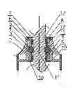
In order to achieve the aforesaid object, the drill head locking apparatus comprises a protruding platform having a through hole, a bearing arranged on the inner wall of a small cylinder on the protruding platform, and a locking sleeve fitted on the protruding platform. The locking sleeve has a protrusion arranged on the upper part of the inner wall of the locking sleeve. The lower part of the inner wall of the locking sleeve is a conical face. A spring is provided between a bottom of the conical face and an upper bottom face of the protruding platform. A press plate is threadedly connected to an outer wall of the top part of the small cylinder on the protruding platform and presses the protrusion. A conical hole is arranged on the wall of the small cylinder on the protruding platform and communicates with the through hole of the protruding platform. A steel ball is arranged in the conical hole.
For the transmission rod to be applied with even force, the drill head locking apparatus comprises two bearings respectively located under the outer wall and above the upper bottom face.
For firmness of the two bearings, a support member is provided between the two bearings.
For convenient connection of a speed reducer, the inner wall of a big cylinder under the protruding platform has inner threads.
A drill head to mate with the aforesaid drill head locking apparatus comprises a front blade portion and a rear transmission rod. The transmission rod has a recess thereon.
When it is necessary to insert the transmission rod, the locking sleeve is pressed down. At this moment, the conical face is moved down and the steel ball rolls outward. After the transmission rod reaches a desired position, the locking sleeve is released. Through the spring, the locking sleeve ascends and the conical face holds against the steel ball to move inward to engage with the recess of the transmission rod in order to position the transmission rod. The drill head locking apparatus and the drill head are easy and convenient to operate, lock firmly, and offer an improved safety.
BRIEF DESCRIPTION OF THE DRAWINGS
FIG. 1 is a sectional view showing the drill head locking apparatus according to a preferred embodiment of the present invention; and
FIG. 2 is a schematic view showing the drill head according to the preferred embodiment of the present invention.
DETAILED DESCRIPTION OF THE PREFERRED EMBODIMENTS
Embodiments of the present invention will now be described, by way of example only, with reference to the accompanying drawings.
As shown in FIG. 1 and FIG. 2, a drill head comprises a front blade portion and a rear transmission rod (13). The transmission rod (13) has a recess (14) thereon. A drill head locking apparatus includes a protruding platform (1) having a through hole and a bearing (8) arranged on an inner wall of a small cylinder on the protruding platform (1). In this embodiment, the drill head locking apparatus comprises two bearings (18) respectively located under an outer wall (7) and above an upper bottom face (10). A support member (12) is provided between the two bearings (8). The two bearings (8) can effectively ensure stability of the transmission rod and decrease heat when rotating. The upper bottom face (10) is threadedly connected with a tightening member (15) to hold against the bearings (8) and the support member (12) so as to enhance firmness of the bearings (8). A locking sleeve (2) is fitted on the protruding platform (1). The locking sleeve (2) has a protrusion (5) arranged on an upper part of an inner wall of the locking sleeve (2). A lower part of the inner wall of the locking sleeve (2) is a conical face (3). A spring (9) is provided between a bottom of the conical face (3) and the upper bottom face (10) of the protruding platform (1). A press plate (6) is threadedly connected to the outer wall (7) of the top part of the small cylinder on the protruding platform (1) and presses the protrusion (5). A conical hole (11) is arranged on the wall of the small cylinder on the protruding platform (1) and communicates with the through hole of the protruding platform (1). A steel ball (4) is arranged in the conical hole (11). The conical hole (11) corresponds in position to the recess (14) of the transmission rod (13) of the drill head. An inner wall of a big cylinder under the protruding platform (1) has inner threads. In this embodiment, the number of the conical holes (11) and the steel balls (4) is two as an equivalent change. The number can be three for a better locking effect.
Although particular embodiments of the present invention have been described in detail for purposes of illustration, various modifications and enhancements may be made without departing from the spirit and scope of the present invention. Accordingly, the present invention is not to be limited except as by the appended claims.
Claims
What is claimed is:1. A drill head locking apparatus, comprising a protruding platform (1) having a through hole, a bearing (8) arranged on an inner wall of a small cylinder on the protruding platform (1), and a locking sleeve (2) fitted on the protruding platform (1), the locking sleeve (2) having a protrusion (5) arranged on an upper part of an inner wall of the locking sleeve (2), a lower part of the inner wall of the locking sleeve (2) being a conical face (3), a spring (9) being provided between a bottom of the conical face (3) and an upper bottom face (10) of the protruding platform (1), a press plate (6) being threadedly connected to an outer wall (7) of a top part of the small cylinder on the protruding platform (1) and pressing the protrusion (5), a conical hole (11) being arranged on a wall of the small cylinder on the protruding platform (1) and communicating with the through hole of the protruding platform (1), a steel ball (4) being arranged in the conical hole (11).
2. The drill head locking apparatus as claimed in claim 1, comprising two bearings (8) respectively located under the outer wall (7) and above the upper bottom face (10).
3. The drill head locking apparatus as claimed in claim 2, wherein a support member (12) is provided between the two bearings (8).
4. The drill head locking apparatus as claimed in one of claims 1 to 3, wherein an inner wall of a big cylinder under the protruding platform (1) has inner threads.
5. A drill head to mate with the drill head locking apparatus as claimed in one of claims 1 to 4, comprising a front blade portion and a rear transmission rod (13), the transmission rod (13) having a recess (14) thereon.
Images & Drawings included:

Sources:
- United States Patent and Trademark Office - verify current appl. status at the USPTO↗
Recent applications in this class:
- » 20250241659 2025-07-31
CONNECTION MEMBER AND METHOD - » 20250235216 2025-07-24
MEDICAL TOOL SYSTEM - » 20250228571 2025-07-17
REAMER DEVICE WITH INTEGRATED DEPTH GAUGING - » 20250204931 2025-06-26
FLEXIBLE SURGICAL TOOL WITH INTEGRATED BEARING ASSEMBLY - » 20250195085 2025-06-19
REAMER DEVICE WITH INTEGRATED DEPTH GAUGING - » 20250072906 2025-03-06
IMPROVEMENTS IN AND RELATING TO MOUNTING SYSTEMS - » 20250049445 2025-02-13
COUPLING APPARATUS FOR ROTARY SURGICAL TOOL - » 20240315706 2024-09-26
IMPROVEMENTS IN AND RELATING TO MOUNTING SYSTEMS - » 20240299043 2024-09-12
TORQUE TRANSMITTING BALL JOINT DRIVER HAVING A RIGID FIXATION MECHANISM - » 20240277349 2024-08-22
SURGICAL TOOL HANDLE ASSEMBLY
Recent applications for this Assignee:
- » 20190024032 2019-01-24
Tissue cell culture device - » 20190024031 2019-01-24
CULTURE DEVICE FOR TISSUE CELL - » 20180305791 2018-10-25
Porous material - » 20180243093 2018-08-30
APPLICATION OF A POROUS MATERIAL - » 20180237888 2018-08-23
POROUS METAL MATERIAL AND PREPARATION METHOD THEREOF - » 20180237733 2018-08-23
CULTURE DEVICE FOR TISSUE CELL SUSPENSION - » 20180236138 2018-08-23
Porous material and preparation method thereof - » 20180236137 2018-08-23
Hierarchical porous material - » 20140235871 2014-08-21
(S)-4-hydroxy-2-oxo-1-pyrrolidineacetamide racemate crystal form II and preparation method therefor - » 20140221670 2014-08-07
4-hydroxy-2-oxo-1-pyrrolidineacetamide racemate crystal form I and preparation method therefor