HOT PLUG FAN AND ELECTRONIC DEVICE HAVING THE SAME
US20130195688A1
2013-08-01
13/445,927
2012-04-13
Abstract:
An electronic device includes a chassis and a hot plug fan. The chassis includes a top plate defining a hole. The hot plug fan includes a main body and two handles rotatably connected to a top of the main body. The main body is received in the chassis through the hole, with the handles exposed out of the hole.
Assignee:
- HON HAI PRECISION INDUSTRY CO., LTD. 12,828 🇹🇼 Tu-Cheng, Taiwan
Interested in similar patents?
Get notified when new applications in this technology area are published.
Classification:
F04D29/601 » CPC main
Details, component parts, or accessories; Mounting; Assembling; Disassembling specially adapted for elastic fluid pumps
F04D19/002 » CPC further
Axial-flow pumps Axial flow fans
F04B53/00 IPC
Component parts, details or accessories not provided for in, or of interest apart from, groups - or -
Description
BACKGROUND
1. Technical Field
The present disclosure relates to an electronic device having a hot plug fan.
2. Description of Related Art
Some electronic devices include hot plug fans for dissipating heat for electronic components in the electronic devices. However, to mount or detach the hot plug fans, the chassis of the electronic devices needs to be opened, which is troublesome.
BRIEF DESCRIPTION OF THE DRAWINGS
Many aspects of the present embodiments can be better understood with reference to the following drawings. The components in the drawings are not necessarily drawn to scale, the emphasis instead being placed upon clearly illustrating the principles of the present embodiments. Moreover, in the drawing, all the views are schematic, and like reference numerals designate corresponding parts throughout the several views.
FIG. 1 is an assembled, isometric view of an exemplary embodiment of a hot plug fan.
FIG. 2 is an exploded, isometric view of the hot plug fan of FIG. 1.
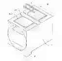
FIG. 3 is a partially isometric view of a chassis of an exemplary embodiment of an electronic device.
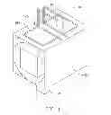
FIG. 4 is an assembled, isometric view of the chassis of FIG. 3 together with the hot plug fan of FIG. 1.
DETAILED DESCRIPTION
The disclosure, including the accompanying drawings, is illustrated by way of example and not by way of limitation. It should be noted that references to “an” or “one” embodiment in this disclosure are not necessarily to the same embodiment, and such references mean at least one.
FIGS. 1 and 2 show an exemplary embodiment of a hot plug fan 10 including a main body 12 and two handles 14.
A connector 121 is formed on the bottom of the main body 12. Two substantially U-shaped recesses 123 are defined in the top of the main body 12, with opposite ends of the recesses 123 facing towards each other. An elongated slot 125 is defined in the top of the main body 12, adjacent to the ends of each recess 123, with two ends of the slot 125 communicating with the distal ends of the recess 123. The slots 125 are parallel to each other. Two pivot holes (not shown) are respectively defined in two end walls bounding each slot 125.
Each handle 14 includes a substantially U-shaped operation portion 141, and two feet 143 respectively extending from two distal ends of the operation portion 141, away from each other.
To assemble the hot plug fan 10, opposite ends of each operation portion 141 are deformed towards each other, to allow the feet 143 of each handle 14 to move towards each other and be inserted into a corresponding one of the slots 125. The operation portions 141 are released to be restored, to allow the feet 143 of each handle 14 to engage in the pivot holes of the corresponding slot 125. Thereby, the handles 14 are rotatably connected to the corresponding slots 125.
FIG. 3 shows an exemplary embodiment of an electronic device including a chassis 30. The chassis 30 includes a top plate 32 and a bottom plate 34 parallel to the top plate 32. A plurality of holes 321 is defined in the top plate 32. A plurality of stop plates 323 is substantially perpendicularly connected between the top plate 32 and the bottom plate 34, two of which bounding on two opposite sides of one of the holes 321.
Referring to FIG. 4, to fix a hot plug fan 10 in the chassis 30, the main body 12 is placed above the chassis 30, aligning with a corresponding hole 321. The main body 12 is manipulated to move down to enter the hole 321, to allow the connector 121 to be connected to a corresponding connector (not shown) in the chassis 30. The handles 14 are rotated onto the corresponding recesses 123, until the operation portions 141 are completely received in the corresponding recesses 123.
To detach the hot plug fan 10, the handles 14 are rotated upwards and pulled upwards. Thereby, the hot plug fan 10 can be easily pulled out of the chassis 30.
Even though numerous characteristics and advantages of the embodiments have been set forth in the foregoing description, together with details of the structure and the functions of the embodiments, the disclosure is illustrative only, and changes may be made in details, especially in matters of shape, size, and arrangement of parts within the principles of the embodiments to the full extent indicated by the broad general meaning of the terms in which the appended claims are expressed.
Claims
What is claimed is:1. A hot plug fan, comprising:
a main body comprising a connector formed on a bottom of the main body; and
two handles rotatably connected to a top of the main body.
2. The hot plug fan of claim 1, wherein each handle comprises a substantially U-shaped operation portion and two feet respectively extending out from two distal ends of the operation portion, two substantially U-shaped recesses are defined in the top of the main body, and two elongated slots are defined in the top of the main body and each slot is adjacent to opposite ends of a corresponding recess, with two ends of the slot respectively communicating with the ends of the corresponding recess, the feet of each handle are pivotably connected to opposite end walls bounding a corresponding one of the slots, when the handles are rotated onto the main body, the operation portions are received in the corresponding recesses.
3. The hot plug fan of claim 2, wherein the ends of the recesses face towards each other, and the slots are parallel to each other.
4. An electronic device, comprising:
a chassis comprising a top plate defining a hole; and
a hot plug fan comprising a main body and two handles rotatably connected to a top of the main body, wherein the main body is received in the chassis through the hole, with the handles exposed out of the hole.
5. The electronic device of claim 4, wherein two stop plates perpendicular to the top plate are formed in the chassis to bound two opposite sides of the hole, the main body of the hot plug fan is sandwiched between the stop plates.
6. The electronic device of claim 4, wherein a connector is directly formed on the bottom of the main body of the hot plug fan, to connect the hot plug fan to the chassis.
7. The electronic device of claim 4, wherein each handle comprises a substantially U-shaped operation portion and two feet respectively extending out from two distal ends of the operation portion, two substantially U-shaped recesses are defined in the top of the main body, and two elongated slots are defined in the top of the main body and each slot is adjacent to opposite ends of the corresponding recess, with two ends of the slot respectively communicating with the ends of the corresponding recess, the feet of each handle are pivotably connected to opposite end walls bounding a corresponding one of the slots, when the handles are rotated onto the main body, the operation portions are received in the corresponding recesses.
8. The electronic device of claim 7, wherein the ends of the recesses face towards each other, and the slots are parallel to each other.
Images & Drawings included:


Sources:
- United States Patent and Trademark Office - verify current appl. status at the USPTO↗
Recent applications in this class:
- » 20130343871 2013-12-26
Series fan assembly structure - » 20130259722 2013-10-03
FAN - » 20130164122 2013-06-27
FASTENER AND FAN ASSEMBLY USING THE SAME - » 20130101404 2013-04-25
ENCLOSURE AND MANIFOLD FOR ADAPTING NONCONFORMING FANS FOR USE IN HARSH OR WET ENVIRONMENTS - » 20130098578 2013-04-25
Cooling fan duct assembly - » 20130052062 2013-02-28
FAN ASSEMBLY - » 20130026334 2013-01-31
Ventilating fan mounting bracket
Recent applications for this Assignee:
- » 20140233961 2014-08-21
Optical communication module including optical-electrical signal converters and optical signal generators - » 20140083669 2014-03-27
HEAT SINK - » 20140063746 2014-03-06
Electronic device with heat dissipation assembly - » 20140061224 2014-03-06
AUTOMATIC VENDING MACHINE - » 20140060914 2014-03-06
Enclosure with shield apparatus - » 20140058727 2014-02-27
MULTIMEDIA RECORDING SYSTEM AND METHOD - » 20140055955 2014-02-27
Fastener - » 20140055322 2014-02-27
DISPLAY SYSTEM AND HEAD-MOUNTED DISPLAY APPARATUS - » 20140054439 2014-02-27
CONTAINER DATA CENTER WITH SUPPORTING APPARATUS - » 20140054311 2014-02-27
AUTOMATIC VENDING MACHINE WITH MOVING MEMBER FOR PRODUCTS