Remote annunciator
US20140028452A1
2014-01-30
13/559,636
2012-07-27
✅ Patent granted
US 8,791,814 B2
2014-07-29
-
-
Tai T Nguyen
Schwegman, Lundberg & Woessner, P.A.
2032-08-18
Abstract:
Some embodiments relate to a remote annunciator 10 that includes an enclosure 11 and a control 12 within the enclosure 11. The control 12 receives signals S from a plurality of transfer switches 13A, 13B, 13C, 13D and at least one generator 14 that is connected to at least one of the transfer switches 13A, 13B, 13C, 13D. The control 12 displays a status of electrical connections that include the plurality of transfer switches 13A, 13B, 13C, 13D and the at least one generator 14. In some embodiments, the control 12 recognizes when the plurality of transfer switches 13A, 13B, 13C, 13D and the at least one generator 14 are connected to the control 12.
Inventors:
- Eric D. Albsmeier 16 🇺🇸 Sheboygan, WI, United States
- Michael T. Little 3 🇺🇸 Sheboygan, WI, United States
- Anthony J. Hackbarth 4 🇺🇸 Sheboygan, WI, United States
Assignee:
- Kohler Co. 1,014 🇺🇸 Kohler, WI, United States
- Kohler Company 3 🇺🇸 Kohler, WI, United States
Applicant:
Interested in similar patents?
Get notified when new applications in this technology area are published.
Classification:
H02J9/06 » CPC main
Circuit arrangements for emergency or stand-by power supply, e.g. for emergency lighting in which the distribution system is disconnected from the normal source and connected to a standby source with automatic change-over, e.g. UPS systems
H02J13/00001 » CPC further
Circuit arrangements for providing remote indication of network conditions, e.g. an instantaneous record of the open or closed condition of each circuitbreaker in the network; Circuit arrangements for providing remote control of switching means in a power distribution network, e.g. switching in and out of current consumers by using a pulse code signal carried by the network characterised by the display of information or by user interaction, e.g. supervisory control and data acquisition systems [SCADA] or graphical user interfaces [GUI]
H02J13/00034 » CPC further
Circuit arrangements for providing remote indication of network conditions, e.g. an instantaneous record of the open or closed condition of each circuitbreaker in the network; Circuit arrangements for providing remote control of switching means in a power distribution network, e.g. switching in and out of current consumers by using a pulse code signal carried by the network; Systems characterised by the controlled or operated power network elements or equipment, the power network elements or equipment not otherwise provided for the elements or equipment being or involving an electric power substation
H02J9/068 » CPC further
Circuit arrangements for emergency or stand-by power supply, e.g. for emergency lighting in which the distribution system is disconnected from the normal source and connected to a standby source with automatic change-over, e.g. UPS systems Electronic means for switching from one power supply to another power supply, e.g. to avoid parallel connection
H02J9/08 » CPC further
Circuit arrangements for emergency or stand-by power supply, e.g. for emergency lighting in which the distribution system is disconnected from the normal source and connected to a standby source with automatic change-over, e.g. UPS systems requiring starting of a prime-mover
Y02B70/30 » CPC further
Technologies for an efficient end-user side electric power management and consumption Systems integrating technologies related to power network operation and communication or information technologies for improving the carbon footprint of the management of residential or tertiary loads, i.e. smart grids as climate change mitigation technology in the buildings sector, including also the last stages of power distribution and the control, monitoring or operating management systems at local level
Y02B90/20 » CPC further
Enabling technologies or technologies with a potential or indirect contribution to GHG emissions mitigation Smart grids as enabling technology in buildings sector
Y02B90/20 » CPC further
Enabling technologies or technologies with a potential or indirect contribution to GHG emissions mitigation Smart grids as enabling technology in buildings sector
Y04S10/40 » CPC further
Systems supporting electrical power generation, transmission or distribution Display of information, e.g. of data or controls
Y04S20/12 » CPC further
Management or operation of end-user stationary applications or the last stages of power distribution; Controlling, monitoring or operating thereof Energy storage units, uninterruptible power supply [UPS] systems or standby or emergency generators, e.g. in the last power distribution stages
Y04S20/248 » CPC further
Management or operation of end-user stationary applications or the last stages of power distribution; Controlling, monitoring or operating thereof; End-user application control systems UPS systems or standby or emergency generators
G08B21/00 IPC
Alarms responsive to a single specified undesired or abnormal condition and not otherwise provided for
G08B29/00 IPC
Checking or monitoring of signalling or alarm systems; Prevention or correction of operating errors, e.g. preventing unauthorised operation
Description
TECHNICAL FIELD
Embodiments pertain to a remote annunciator, and more particularly to a remote annunciator that displays a status of electrical connections between a plurality of transfer switches and at least one generator.
BACKGROUND
Many existing remote annunciators offer support for either a single genset or a single genset and single ATS unit. One of the drawbacks with such systems is that there are typically many gensets that are installed with multiple ATS units. Therefore, multiple remote annunciators are usually required in order to adequately monitor multiple ATS's and gensets. This requirement for multiple remote annunciators adds unwanted cost and complexity to remotely monitoring various electrical systems that include such components.
Some existing remote annunciators are able to annunciate with more than one ATS. However, these types of remote annunciators are unable to annunciate any type of genset status. Therefore, one of the drawbacks is such remote annunciator is that an additional type of remote annunciator is typically required in order to adequately monitor the status of the genset and the multiple ATS's.
BRIEF DESCRIPTION OF THE DRAWINGS
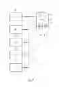
FIG. 1 is a schematic view illustrating an example remote annunciator that includes wired connections with multiple ATS's and at least one generator.
FIG. 2 is a schematic view illustrating an example remote annunciator that includes wireless connections with multiple ATS's and at least one generator.
FIG. 3 illustrates an example indicator that may be used with the example remote annunciators that are illustrated in FIGS. 1 and 2.
DETAILED DESCRIPTION
The following description and the drawings sufficiently illustrate specific embodiments to enable those skilled in the art to practice them. Other embodiments may incorporate structural, logical, electrical, process, and other changes. Portions and features of some embodiments may be included in, or substituted for, those of other embodiments. Embodiments set forth in the claims encompass all available equivalents of those claims.
FIG. 1 illustrates an example remote annunciator 10 that includes an enclosure 11 and a control 12 within the enclosure 11. The control 12 receives signals S from a plurality of transfer switches 13A, 13B, 13C, 13D and at least one generator 14 that is connected to at least one of the transfer switches 13A, 13B, 13C, 13D. The control 12 displays a status of electrical connections that include the plurality of transfer switches 13A, 13B, 13C, 13D and the at least one generator 14.
In some embodiments, the control 12 recognizes when the plurality of transfer switches 13A, 13B, 13C, 13D and the at least one generator 14 are connected to the control 12.
As shown in FIG. 1, the control 12 is connected to the plurality of transfer switches 13A, 13B, 13C, 13D and the at least one generator 14 via a wired connection W. The control 12 sends out signals S to the plurality of transfer switches 13A, 13B, 13C, 13D and the at least one generator 14 via the wired connection W to determine a status of the plurality of transfer switches 13A, 13B, 13C, 13D and the at least one generator 14. In some embodiments, the control 12 sends signals to the plurality of transfer switches 13A, 13B, 13C, 13D and the at least one generator 14 via the wired connection W to determine a status of the electrical connections that include the plurality of transfer switches 13A, 13B, 13C, 13D and the at least one generator 14.
As an example, the control 12 may be connected to the plurality of transfer switches 13A, 13B, 13C, 13D and the at least one generator 14 via a wired ModBus RTU connection. As another example, the control 12 may be connected to the plurality of transfer switches 13A, 13B, 13C, 13D and the at least one generator 14 via a wired ModBus TCP connection. Embodiments are also contemplated where the control 12 broadcasts signals S (see FIG. 2) to the plurality of transfer switches 13A, 13B, 13C, 13D and the at least one generator 14 via an Ethernet UDP connection to determine a status of the electrical connections that include the plurality of transfer switches 13A, 13B, 13C, 13D and the at least one generator 14.
As shown in FIG. 2, the control 12 may be connected to the plurality of transfer switches 13A, 13B, 13C, 13D and the at least one generator 14 via a wireless connection. In sonic embodiments, the control 12 receives wireless signals from the plurality of transfer switches 13A, 13B, 13C, 13D and the at least one generator 14 via the wireless connection to determine a status of the plurality of transfer switches 13A, 13B, 13C, 13D and the at least one generator 14.
As an example, the control 12 may receive signals from the plurality of transfer switches 13A, 13B, 13C, 13D and the at least one generator 14 to determine a status of the electrical connections that include the plurality of transfer switches 13A, 13B, 13C, 13D and the at least one generator 14. Embodiments are contemplated where the control 12 is connected to the plurality of transfer switches 13A, 13B, 13C, 13D and the at least one generator 14 via a wireless ModBus TCP connection.
As shown in FIGS. 1 and 2, the remote annunciator 10 may further include an indicator 20 that displays a status of the electrical connections that include the plurality of transfer switches 13A, 13B, 13C, 13D and the at least one generator 14. One example indicator 20 that may be provided with the remote annunciator 110 is shown in detail in FIG. 3.
As shown in FIG. 3, the indicator 20 includes at least one LED that displays a status of the plurality of transfer switches 13A, 13B, 13C, 13D (4 are shown in FIG. 3) and the at least one generator 14 (one is shown in FIG. 3). In the example embodiment that is illustrated in FIG. 3, the indicator 20 includes at least one LED that displays a status of the electrical connections that include plurality of transfer switches 13A, 13B, 13C, 13D (4 are shown in FIG. 3) and the at least one generator 14 (one is shown in FIG. 3).
Other embodiments are contemplated where the indicator 20 includes at least one LCD (not shown) that displays a status of the plurality of transfer switches 13A, 13B, 13C, 13D and the at least one generator 14. As an example, the indicator 20 may include at least one LCD that displays a status of the electrical connections that include plurality of transfer switches 13A, 13B, 13C, 13D and the at least one generator 14.
As shown in FIG. 3, the remote annunciator 10 may further include further include a test button 25 that is connected to the control 12. The control 12 may simulate a power outage at any or more of the plurality of transfer switches 13A, 13B, 13C, 13D once the test button 25 is activated, in the example embodiment that is shown in FIG. 3, the remote annunciator 10 further includes a plurality of test buttons 25 that are each connected to the control 12. The control 12 is able to simulate a power outage at a particular one of the plurality of transfer switches 13A, 13B, 13C, 13D once the test button 25 that is associated with the particular one of the plurality of transfer switches 13A, 13B, 13C, 13D is activated.
Embodiments are contemplated where the remote annunciator includes a selector switch (not shown in FIGS.) that is connected to the control 12. In embodiments that include a selector switch, the control 12 may simulate a power outage at a particular one of the plurality of transfer switches 13A, 13B, 13C, 13D based on the position of the selector switch once the singular test button 25 is activated.
The remote annunciators 10 described herein offer support for multiple ATS units and at least one genset. Therefore, multiple remote annunciators are not required in order to adequately monitor multiple ATS's and gensets. Therefore, the remote annunciators 10 described herein reduce unwanted cost and complexity that are associated with remotely monitoring various electrical systems that include such components.
The Abstract is provided to comply with 37 C.F.R. Section 1.72(b) requiring an abstract that will allow the reader to ascertain the nature and gist of the technical disclosure. It is submitted with the understanding that it will not be used to limit or interpret the scope or meaning of the claims. The following claims are hereby incorporated into the detailed description, with each claim standing on its own as a separate embodiment.
Claims
What is claimed is:1. A remote annunciator comprising:
an enclosure; and
a control within the enclosure, wherein the control receives signals from a plurality of transfer switches and at least one generator that is connected to at least one of the transfer switches, wherein the control displays a status of electrical connections that include the plurality of transfer switches and the at least one generator.
2. The remote annunciator of claim 1, wherein the control recognizes when the plurality of transfer switches and the at least one generator are connected to the control.
3. The remote annunciator of claim 1, wherein the control is connected to the plurality of transfer switches and the at least one generator via a wired connection.
4. The remote annunciator of claim 3, wherein the control sends out signals to the plurality of transfer switches and the at least one generator via the wired connection to determine a status of the plurality of transfer switches and the at least one generator.
5. The remote annunciator of claim 3, wherein the control broadcasts signals to the plurality of transfer switches and the at least one generator via the wired connection to determine a status of the electrical connections that include the plurality of transfer switches and the at least one generator.
6. The remote annunciator of claim 3, wherein the control is connected to the plurality of transfer switches and the at least one generator via a wired ModBus RTU connection.
7. The remote annunciator of claim 3, wherein the control is connected to the plurality of transfer switches and the at least one generator via a wired ModBus TCP connection.
8. The remote annunciator of claim 1, wherein the control is connected to the plurality of transfer switches and the at least one generator via a wireless connection.
9. The remote annunciator of claim 8, wherein the control receives wireless signals from the plurality of transfer switches and the at least one generator via the wireless connection to determine a status of the plurality of transfer switches and the at least one generator.
10. The remote annunciator of claim 8, wherein the control receives signals from the plurality of transfer switches and the at least one generator to determine a status of the electrical connections that include the plurality of transfer switches and the at least one generator.
11. The remote annunciator of claim 8, wherein the control is connected to the plurality of transfer switches and the at least one generator via a wireless ModBus TCP connection.
12. The remote annunciator of claim 1, wherein the control broadcasts signals to the plurality of transfer switches and the at least one generator via an Ethernet UDP connection to determine a status of the electrical connections that include the plurality of transfer switches and the at least one generator.
13. The remote annunciator of claim 1, further comprising an indicator that displays a status of the electrical connections that include the plurality of transfer switches and the at least one generator.
14. The remote annunciator of claim 13, wherein the indicator includes at least one LED that displays a status of the plurality of transfer switches and the at least one generator.
15. The remote annunciator of claim 13, wherein the indicator includes at least one LED that displays a status of the electrical connections that include plurality of transfer switches and the at least one generator.
16. The remote annunciator of claim 1, wherein indicator includes at least one LCD that displays a status of the plurality of transfer switches and the at least one generator.
17. The remote annunciator of claim 16, wherein indicator includes at least one LCD that displays a status of the electrical connections that include plurality of transfer switches and the at least one generator.
18. The remote annunciator of claim 1, further comprising a test button that is connected to the control, wherein the control simulates a power outage at any of the plurality of transfer switches once the test button is activated.
19. The remote annunciator of claim 18, further comprising a plurality of test buttons that are each connected to the control, wherein the control simulates a power outage at a particular one of the plurality of transfer switches once the test button that is associated with the particular one of the plurality of transfer switches is activated.
20. The remote annunciator of claim 1, further comprising:
a test button that is connected to the control; and
a selector switch that is connected to the control, wherein the control simulates a power outage at a particular one of the plurality of transfer switches based on the position of the selector switch once the test button is activated.
Images & Drawings included:


Sources:
- United States Patent and Trademark Office - verify current appl. status at the USPTO↗
Similar patent applications:
- » 20080007879
GFCI with self-test and remote annunciation capabilities - » 16744013
Remote annunciator - » 20050225442
Mechanical security system, control device, remote annunciator, control method and control program, computer-readable recording medium recording control program - » 11120779
Remote annunciator - » 20140015482
REMOTE ANNUNCIATOR FOR ELECTRIC VEHICLE SUPPLY EQUIPMENT - » 20090191921
Remote Annunciator System and Method for a Plurality of Wireless Handheld Devices - » 20080224846
Remote service audible arming state annunciation
Recent applications in this class:
- » 20250286402 2025-09-11
ELECTRICAL SUBMERSIBLE PUMPING SYSTEM WITH A RIDE THROUGH POWER SUPPLY HAVING A SAFETY INTERLOCK - » 20250279671 2025-09-04
ENERGY CONTROL SYSTEM - » 20250279670 2025-09-04
STORAGE APPARATUS, POWER SUPPLYING METHOD, AND PROGRAM - » 20250246929 2025-07-31
REDUNDANT POWER SUPPLY SYSTEM - » 20250233445 2025-07-17
BACKUP POWER BOX AND CONTROL METHOD FOR BACKUP POWER BOX - » 20250233444 2025-07-17
UNINTERRUPTIBLE POWER MODULES FOR UNINTERRUPTIBLE POWER SUPPLIES (UPSs) AND RELATED UNINTERRUPTIBLE POWER MODULES - » 20250226687 2025-07-10
ENERGY STORAGE SYSTEM AND START METHOD THEREOF - » 20250211020 2025-06-26
UNINTERRUPTIBLE POWER SUPPLY WITH INTEGRATED MAINTENANCE BYPASS CABINET ALLOWING REDUCED U-HEIGHT AND INCREASED AIRFLOW - » 20250192603 2025-06-12
POWER SUPPLY SYSTEM, AND CONTROL METHOD AND APPARATUS - » 20250183700 2025-06-05
GRID POWER LOSS DETECTION TECHNIQUE
Recent applications for this Assignee:
- » 20250271098 2025-08-28
GRAB BAR ASSEMBLY - » 20250269395 2025-08-28
FILTERED SPRAY HEAD ASSEMBLY - » 20250268787 2025-08-28
HOT AND COLD THERAPY SYSTEM - » 20250251122 2025-08-07
ILLUMINATED BATH CADDY - » 20250223787 2025-07-10
SHOWER CONTROL SYSTEM - » 20250222474 2025-07-10
AROMATIC FOG GENERATOR FOR BATHING ENVIRONMENTS - » 20250198141 2025-06-19
SHOWER TRIM ASSEMBLY - » 20250196168 2025-06-19
KINETIC WATER DELIVERY DEVICES - » 20250154752 2025-05-15
FAUCET WITH INTERCHANGEABLE HANDLE - » 20250153202 2025-05-15
DUAL-HEAD SHOWER ASSEMBLIES