Valve core remover extension
US20140215786A1
2014-08-07
14/072,643
2013-11-05
✅ Patent granted
US 9,943,951 B2
2018-04-17
-
-
Monica Carter | Nirvana Deonauth
2035-09-30
Abstract:
This set of four assorted extensions and removing rod is designed to assist a tool used in pressurized HVAC systems having a removable valve core. The existing universal valve core removal tool is not able to access many pressurized systems. These extensions working together with the universal valve core removing tool, allow for ample clearance.
Assignee:
- Adam Munguia 1 🇺🇸 Houston, TX, United States
Applicant:
Interested in similar patents?
Get notified when new applications in this technology area are published.
Classification:
B25B27/24 » CPC main
Hand tools, specially adapted for fitting together or separating parts or objects whether or not involving some deformation, not otherwise provided for for assembling objects other than by press fit or detaching same mounting or demounting valves
Y10T29/53596 » CPC further
Metal working; Means to assemble or disassemble; Valve applying or removing Removal tool
B23P19/04 IPC
Machines for simply fitting together or separating metal parts or objects, or metal and non-metal parts, whether or not involving some deformation ; Tools or devices therefor so far as not provided for in other classes for assembling or disassembling parts
Description
CROSS REFERENCE TO RELATED APPLICATIONS
This application is a continuation-in-part of application Ser. No. 14/072,643, filed Nov. 5, 2013 and incorporates by reference application Ser. No. 61/796,271, filed on Nov. 6, 2012 entitled “Valve Core Remover Extension”.
BACKGROUND OF INVENTION
In the HVAC field it has become very important, when servicing high pressurized systems, to remove and replace leaking Schrader valve cores. The EPA has a great concern on the handling and release of refrigerant gas. There is a tool presently on the market today in the HVAC field that will safely remove the valve elements from pressurized air conditioning systems. This tool is called a universal valve core removal tool, but there are some issues with this tool as it is not able to access many ac systems due to its size.
There seemed to be a need for some improvements and so these extensions were created in several variations to assist the existing core remover tool by providing better accessibility.
SUMMARY OF THE INVENTION
These extensions that were invented are designed to work in conjunction with a tool on the market today. They are comprised: to attach to the valve core removing tools first opening and the second opening to extend the valve assembly for proper access where the existing valve core remove tool can't access the service valve point with precision the way it's designed to. The extensions allow the same passageways between the first opening and the second opening of the tools.
The extension valve tip couples to the first opening of the valve assembly, which extends the valve assembly from obstructions. The extension sleeve's compression nut adapter is adapted to the pressurized valve access points, and the 4-⅛″ extension sleeve couples to the second opening of the valve assembly tool. This allows a longer valve core extracting rod/shaft assembly coupling to the 4-⅛″ extension sleeve, allowing the longer extracting rod/shaft assembly to move freely through all three passageways.
FIELD OF INVENTION
This set of four extensions & removal rod is a uniquely design invention that can be used together with a tool presently on the market today used for removing valve elements from pressurized air conditioning systems.
ABSTRACT
This set of four assorted extensions and removing rod is designed to assist a tool used in pressurized HVAC systems having a removable valve core. The existing universal valve core removal tool is not able to access many pressurized systems. These extensions working together with the universal valve core removing tool, allow for ample clearance.
BRIEF DESCRIPTION OF THE DRAWINGS
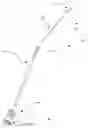
FIG. 1 shows the various components of the valve core extracting rod/shaft 500. The illustrated view is ready for assembly to one another.
FIG. 2 illustrates the preparing of the universal line service valve.
FIG. 3 illustrates the preparing of the compression nut.
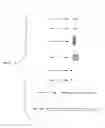
FIG. 4 shows the preparation and assembly of the 4-⅛″ straight extension 600.
FIG. 5 shows the preparation and assembly of the 6-⅞″ straight extension 700.
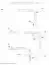
FIG. 6 shows the preparation and assembly of the 2-½″ offset extension 800.
FIG. 7 shows the preparation and assembly of the Ninety degree extension 900.
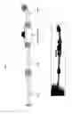
FIG. 8 shows the extracting rod/shaft & extensions assembled to the universal valve assembly.
DETAILED DESCRIPTION OF DRAWINGS (FIGS. 1-8)
FIG. 0 description of materials for extracting rod/shaft.
FIG. 1 prep & assemble; extracting rod/shaft 500, apply JB weld epoxy to one end of steel cable 3a and insert extractor head 1a to steel cable 3a, apply JB weld to small nail 2a, insert through small hole of extractor head 1a, and allow epoxy to setup. Apply JB weld ¾″ to opposite end of steel cable 3a, insert steel cable 3a in to ¾″×⅛″ deep hole of brass rod/shaft 4a, apply JB weld to small nail head/(ball stop) 5a and imbed on to small hole, side of brass rod/shaft 4a and allow epoxy to setup.
Opposite side of brass rod/shaft 4a, insert compression nut 6a sliding threaded end through first. Imbed shaft control knob 7a to brass rod/shaft 4a, insert ⅛″ set pin 8a through hole of shaft control knob 7a and brass rod/shaft 4a.
FIG. 2 debraze and separate service valve 101 from copper tube discarding copper tube. Bore through service valve 101 with ¼″ drill bit. Four service valves needed for this kit.
FIG. 3 compression nut 102 is removed from a hvac refrigerant hose. Bore through compression nut 102 with 5/16″ drill bit carefully not damaging inner threads. Four compression nuts are needed for this kit.
FIG. 4 prep & assemble; 4-⅛″ straight extension 600. 5/16″D×3-⅛″L copper tube 103, swedge one end of copper tube 103 to ⅜″, and insert compression nut 102 sliding threaded end through first. Swedge opposite end of copper tube 103 to ⅜″ insert and braze service valve 101 to this end of copper tube 103.
FIG. 5 prep & assemble; 6-⅞″ straight extension 700. 5/16″D×6-⅛″L copper tube 104; swedge one end of copper tube 104 to ⅜″, and insert compression nut 102 sliding threaded end through first. Swedge opposite end of copper tube 104 to ⅜″ insert and braze service valve 101 to this end of copper tube 104.
FIG. 6 prep & assemble; 2-½″ offset extension 800. 5/16″D×2-½″L copper tube 105, bend copper tube 105 twenty degrees and swedge one end to ⅜″, and insert compression nut 102 sliding threaded end through first. Swedge opposite end of copper tube 105 to ⅜″ insert and braze service valve 101 to this end of copper tube 105.
FIG. 7 prep & assemble; ninety degree extension 900. 5/16″D×6-⅛″L copper tube 106; bend copper tube 106 ninety degrees and swedge one end to ⅜″, and insert compression nut 102 sliding threaded end through first. Swedge opposite end of copper tube 106 to ⅜″ insert and braze service valve 101 to this end of copper tube 106.
FIG. 8 Extracting rod/shaft 500, straight extension 600, and offset extension 800 assembled to the universal valve assembly.
Claims
1. The remover rod/shaft and the extension sleeves were designed to work with an existing tool, a Schrader valve core remover, used in the HVAC industry. I discovered issues using the existing valve core removing tool; it was not able to access the service valves on some a/c units. The tool was too large in width and the valves could not be removed. In some cases the a/c systems cannot be pumped down due to the age of the a/c condensers, therefore the refrigerant would have to be reclaimed, the systems would have to be vacuumed and recharged. The valve core remover extension rod/shaft and sleeves, allows the existing Schrader valve core remover to work with ease. It is a very unique and special design that can be used on most HVAC systems.
Images & Drawings included:


Sources:
- United States Patent and Trademark Office - verify current appl. status at the USPTO↗
Recent applications in this class:
- » 20240042585 2024-02-08
Seatdriver - » 20220339765 2022-10-27
Valve seat puller head assembly - » 20220184785 2022-06-16
Core pulling tool - » 20220168878 2022-06-02
Valve seat removal impact driver attachment device - » 20220063072 2022-03-03
Injection fitting internal check valve retrieval tool - » 20210308848 2021-10-07
Faucet cartridge removal tool - » 20210138620 2021-05-13
Flow control valve assembly and complementary adjustment tool set - » 20200055172 2020-02-20
Seat insert tool - » 20190291252 2019-09-26
Reyse Jatzlau Valve Buddy - » 20180304451 2018-10-25
Moen® type valve cartridge extractor tool having both right-hand and left-hand threads