Method and device at a vehicle differential brake
US20140256492A1
2014-09-11
14/350,114
2012-10-25
✅ Patent granted
US 9,470,300 B2
2016-10-18
WO; PCT/EP2012/071146; 20121025
WO; WO2013/060775; 20130502
Justin Holmes
BrooksGroup
2033-02-26
Abstract:
In a driveline in a front wheel drive vehicle the distribution of drive torque to the drive wheels (1) via a differential (6) is controlled by means of a differential brake with a hydraulically controlled limited slip clutch (7). A low preparatory hydraulic pressure is applied to the clutch at the occurrence of any one of certain predetermined driving situations for decreasing the response time for the clutch.
Assignee:
- BorgWarner TorqTransfer Systems AB 16 🇸🇪 Landskrona, Sweden
Applicant:
Interested in similar patents?
Get notified when new applications in this technology area are published.
Classification:
F16H48/22 » CPC main
Differential gearings; Arrangements for suppressing or influencing the differential action, e.g. locking devices using friction clutches or brakes
B60K17/20 » CPC further
Arrangement or mounting of transmissions in vehicles characterised by arrangement, location, or kind of gearing of differential gearing in which the differential movement is limited
F16D48/066 » CPC further
External control of clutches; Control by electric or electronic means, e.g. of fluid pressure Control of fluid pressure, e.g. using an accumulator
F16D2500/1024 » CPC further
External control of clutches by electric or electronic means; System to be controlled; Actuator; Electrical type; Electric motor combined with hydraulic actuation
F16D2500/10412 » CPC further
External control of clutches by electric or electronic means; System to be controlled; Clutch; Clutch position Transmission line of a vehicle
F16D2500/10425 » CPC further
External control of clutches by electric or electronic means; System to be controlled; Clutch; Clutch position Differential clutch
F16D2500/3024 » CPC further
External control of clutches by electric or electronic means; Signal inputs from the actuator Pressure
F16D2500/3101 » CPC further
External control of clutches by electric or electronic means; Signal inputs from the vehicle Detection of a brake actuation by a sensor on the brake
F16D2500/3109 » CPC further
External control of clutches by electric or electronic means; Signal inputs from the vehicle; Vehicle speed Vehicle acceleration
F16D2500/31426 » CPC further
External control of clutches by electric or electronic means; Signal inputs from the user input from pedals Brake pedal position
F16D2500/5014 » CPC further
External control of clutches by electric or electronic means; Problem to be solved by the control system; Relating the actuator Filling the actuator cylinder with fluid
F16D2500/525 » CPC further
External control of clutches by electric or electronic means; Problem to be solved by the control system; General Improve response of control system
F16D2500/7041 » CPC further
External control of clutches by electric or electronic means; Details about the implementation of the control system; Output parameters from the control unit; Target parameters to be controlled; Actuator parameters Position
F16D2500/70406 » CPC further
External control of clutches by electric or electronic means; Details about the implementation of the control system; Output parameters from the control unit; Target parameters to be controlled; Actuator parameters Pressure
F16D2500/70426 » CPC further
External control of clutches by electric or electronic means; Details about the implementation of the control system; Output parameters from the control unit; Target parameters to be controlled; Clutch parameters Clutch slip
F16D2500/70663 » CPC further
External control of clutches by electric or electronic means; Details about the implementation of the control system; Strategy of control State analysis; Analysing potential states of the machine and developing control strategies at each state
F16H48/32 » CPC further
Differential gearings; Arrangements for suppressing or influencing the differential action, e.g. locking devices using externally-actuatable means using fluid pressure actuators
F16H2048/204 » CPC further
Differential gearings; Arrangements for suppressing or influencing the differential action, e.g. locking devices Control of arrangements for suppressing differential actions
B60K17/16 IPC
Arrangement or mounting of transmissions in vehicles characterised by arrangement, location, or kind of gearing of differential gearing
F16D48/06 IPC
External control of clutches Control by electric or electronic means, e.g. of fluid pressure
F16H48/20 IPC
Differential gearings Arrangements for suppressing or influencing the differential action, e.g. locking devices
Description
TECHNICAL FIELD
The present invention relates to a method in a driveline in a vehicle, preferably a front wheel drive vehicle, for controlling the distribution of drive torque to two drive wheels via a differential being provided with a differential brake with a hydraulically controlled limited slip clutch. It also relates to a device for carrying out this method.
BACKGROUND OF THE INVENTION
The differential brake, electronically controlled via the clutch, is only used at certain driving conditions, and it may thus take several minutes or more under normal driving conditions between two consecutive operations thereof. This means that the clutch may return to an “idling” condition (with its clutch discs fully separated from each other) and that the response time, when a controlling torque is needed in the clutch, may be long.
THE INVENTION
The main object of the invention is to remove the drawback with the long response time in certain situations. This is according to the invention attained in that a low preparatory hydraulic pressure is applied to the clutch at the occurrence of any one of certain predetermined driving situations.
This preparatory hydraulic pressure is preferably of a magnitude to bring clutch discs of the clutch in contact with each other but not to influence driving dynamics of the vehicle and may be applied in situations, where a controlling action of the clutch may be envisaged shortly.
The preparatory hydraulic pressure may for example be applied a certain time after the brake pedal of the vehicle is released, or when the vehicle is accelerating while negotiating a sharp curve, or when the steering wheel of the vehicle, running at high speed, is turned.
BRIEF DESCRIPTION OF THE DRAWINGS
The invention will be described in further detail below under reference to the accompanying drawings, in which
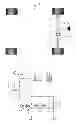
FIG. 1 is a schematic illustration of a driveline layout for a front wheel drive (FWD) road vehicle,
FIG. 2 is an exemplary hydraulic scheme for a control system of a limited clutch in the driveline of FIG. 1, and
FIG. 3 is a block diagram to illustrate the invention.
DETAILED DESCRIPTION OF EMBODIMENTS
FIG. 1 is a schematic illustration of a driveline layout for a front wheel drive (FWD) road vehicle. The vehicle has two driven front wheels 1 and two undriven rear wheels 2 in a chassis. As is well known to any person skilled in the art, the front wheels 1 are driven by an engine 3 via a gear box 4 and two half-axles 5, connected by means of a conventional differential 6, capable of transmitting torque to the two half-axles 5, which may rotate with different speeds for example at curve negotiation.
At certain situations, the ground grip for one drive wheel 1 may be partially or totally lost, resulting in wheel slip and loss of torque transfer or traction for the other drive wheel. This undesirable effect of the conventional differential may as known be obviated by the provision of a differential brake, which has the effect of partially or totally “short-circuiting” the differential by connecting the two half-axles 5 with each other. A differential brake in the form of a hydraulically controlled, limited slip clutch 7 is illustrated in FIG. 1. By engaging this clutch 7 the speed differential and torque distribution between the two half-axles may be controlled.
FIG. 2 illustrates a hydraulic control system, which is an example of a system that can be used for controlling multiple discs or a disc package 8 of the limited slip clutch 7. When the discs 8 are brought into engagement with each other by a hydraulic cylinder 9, the clutch 7 is engaged. This hydraulic control system is previously shown and described in detail in WO 2011/043722, to which reference is made. It may herein suffice to note the presence of a hydraulic pump 10 driven by an electric motor 11. On the same shaft as the pump 10 there is a centrifugal regulator 12 controlling the position of a pressure overflow valve 13. The system also contains a relief valve 14.
The motor 11 is constantly running, but its rotational speed is increased for increasing the hydraulic pressure to the cylinder 9 and thus for engaging the multiple discs 8 of the clutch 7. The clutch 7 can be controlled by the system with great accuracy and with reasonably low response time due to the constantly running motor 11. The maximum hydraulic pressure in the system may for example be set at 40 bar.
As already stated, the differential brake in the form of the clutch 7 is only operational under certain circumstances to be dealt with below. Such circumstances may only occur at rather long intervals, such as several minutes or more. This means that the hydraulic control system is “idling” and that the hydraulic pressure therein goes down to nil, so that the multiple discs 8 of the clutch 7 are at maximum distance from each other.
When there is a need for engaging the clutch 7, the time for pressurizing the hydraulic system and compressing the multiple discs 8 may be in the order of >250 ms, which may be too much in this use for controlling a differential brake.
A solution to the problem with too long response times may according to the invention be to apply a certain low preparatory hydraulic pressure in the cylinder 9, when certain predetermined driving situations occur. Such driving situations may be detected by existing means in the vehicle, and the processing for applying this pressure may be handled by the ordinary electronic control system for the differential brake.
The preparatory hydraulic pressure shall be so low that the driving dynamics of the vehicle are not influenced, but still high enough for applying the discs of the multiple discs 8 against each other or in other words for reaching a “kiss-point” for the disc package. At a maximum hydraulic pressure in the system of 40 bar, the preparatory pressure may for example be in the order of 1 bar. The use of the preparatory hydraulic pressure may drastically improve the response time after an “idling” interval. The software of the electronic control system for the differential brake may in one version contain three main areas: pre-load, slip-control and yaw-damping.
The pre-load area of the software may engage or lock the clutch 7, when the vehicle is to be started from a standstill. This is a preventive measure to avoid loosing the grip for any of the driving wheels, having a poorer grip on the ground than the other. The slip-control will apply a torque on the clutch 7 at the occurrence of a decreased grip for one of the driving wheels during operation.
The yaw-damping will apply a torque on the clutch 7, when over-steering of the vehicle occurs, and tends to right or stabilize the vehicle.
In this environment and only to be seen as examples of uses, the preparatory hydraulic pressure may be applied by an electronic response system in the following driving situations requiring quicker response times than may be provided without the preparatory hydraulic pressure.
-
- The vehicle holds at red light, and the driver has the foot brake applied. When the brake pedal is released, the preparatory hydraulic pressure is applied for say 2 seconds for improving the response time for the pre-load to possibly come. If the pre-load is not used within this time period, it has to be assumed that the preparatory hydraulic pressure is not needed, because the driver did not plan a quick start.
- A sharp curve is negotiated during acceleration. The gas pedal position in combination with the high lateral acceleration indicates that the inner drive wheel may loose its grip and start spinning The preparatory hydraulic pressure is applied for decreasing the response time if needed for the slip-control torque.
- The steering wheel is turned somewhat, when the vehicle is running at high speed. This indicates that a yaw-damping may be needed, and the preparatory hydraulic pressure is applied.
It shall be noted that other driving situations where the quick response of the clutch 7 may be required are possible. Also, it is important to note that the invention is not limited to its use with the shown and described clutch and its control system.
FIG. 3 is a block diagram illustrating the invention. A data bus in a modern vehicle contains detailed information about the vehicle and its behavior during driving.
The vehicle state is thus constantly calculated. If a predetermined driving situation requiring a quick response from the clutch 7 occurs, the response system controls the application of the preparatory hydraulic pressure for engaging the disc package 8 to the “kiss-point”.
The invention has been shown and described in its use for a front wheel drive vehicle, but its basic ideas are equally applicable to a rear wheel drive vehicle.
Modifications are possible within the scope of the appended claims.
Claims
1. A method in a driveline in a vehicle for controlling the distribution of drive torque to two drive wheels via a differential being provided with a differential brake with a hydraulically controlled limited slip clutch, comprising applying a low preparatory hydraulic pressure to the clutch at the occurrence of any one of certain predetermined driving situations.
2. A method according to claim 1, wherein the preparatory hydraulic pressure is of a magnitude to bring clutch discs of the clutch in contact with each other but not to influence driving dynamics of the vehicle.
3. A method according to claim 1, wherein the applying the low preparatory hydraulic pressure is carried out in situations, where a controlling action of the clutch is envisaged shortly.
4. A method according to claim 3, wherein the preparatory hydraulic pressure is applied a certain time after the brake pedal of the vehicle is released.
5. A method according to claim 3, wherein the preparatory hydraulic pressure is applied, when the vehicle is accelerating while negotiating a sharp curve.
6. A method according to claim 3, wherein the preparatory hydraulic pressure is applied, when the steering wheel of the vehicle, running at high speed, is turned.
7. A driveline in a vehicle, preferably a front wheel drive vehicle, comprising a differential for distributing a drive torque to two drive wheels and a differential brake with a hydraulically controlled limited slip clutch comprising a response system for controlling the supply of a preparatory hydraulic pressure to the clutch at the occurrence of any one of certain predetermined driving situations.
Images & Drawings included:

Sources:
- United States Patent and Trademark Office - verify current appl. status at the USPTO↗
Recent applications in this class:
- » 20250251035 2025-08-07
AXLE DRIVING DEVICE - » 20250237297 2025-07-24
SUB-ASSEMBLY FOR E-AXLE - » 20250224024 2025-07-10
LIMITED SLIP DIFFERENTIAL UNIT - » 20250215964 2025-07-03
DIFFERENTIAL AND VEHICLE INCLUDING THE SAME - » 20250137518 2025-05-01
DRIVE DEVICE FOR A VEHICLE AXLE - » 20250102051 2025-03-27
POWER TRANSMISSION DEVICE FOR VEHICLE - » 20250084917 2025-03-13
DIFFERENTIAL DEVICE - » 20250067328 2025-02-27
DIFFERENTIAL ASSEMBLY AND ACTUATOR ASSEMBLY FOR FRICTION DISK CLUTCH - » 20240167552 2024-05-23
Differential gear unit - » 20240003416 2024-01-04
Limited-slip differential system
Recent applications for this Assignee:
- » 20180238443 2018-08-23
Method of controlling a drive train - » 20180170168 2018-06-21
Gearbox - » 20170151872 2017-06-01
A VEHICLE DRIVELINE SYSTEM - » 20170059023 2017-03-02
Torque vectoring device - » 20160312880 2016-10-27
Lubrication arrangement for a unit in a vehicle - » 20160048133 2016-02-18
Hydraulic pump assembly - » 20160010706 2016-01-14
Method for operating a hydraulic disc coupling in an AWD vehicle and a coupling therefore - » 20150065283 2015-03-05
Electric drive axle arrangement for a road vehicle - » 20150014071 2015-01-15
Electrically driven vehicle drive axle arrangement - » 20140283648 2014-09-25
GEARBOX INTEGRATED IN ROTOR OF ELECTRICAL MOTOR