WHEELED SCOOPER
US20150089846A1
2015-04-02
14/493,751
2014-09-23
Abstract:
A wheeled scooper is provided. The wheeled scooper reduces the time and effort needed in collecting, transporting and dumping materials. The scooper provides an elongated handle that may be transversely and forwardly pivotably connected to a collector member. The collector member may provide a front opening to a collection space defined by a front edge. The scooper may provide a set of wheels rotatably mounted near a lower rear portion of the collector member so that a user can control the elongated handle to steer the scooper over a supporting surface and easily scoop, transport and dump material into its collection space by means of the positionable front edge.
Interested in similar patents?
Get notified when new applications in this technology area are published.
Classification:
A01K1/0114 » CPC main
Housing animals; Equipment therefor; Removal of dung or urine, e.g. from stables; Cat trays; Dog urinals; Toilets for pets Litter boxes with screens for separating excrement from litter
E01H1/006 » CPC further
Removing undesirable matter from roads or like surfaces, with or without moistening of the surface Specially adapted for removing excrements
A01K1/01 IPC
Housing animals; Equipment therefor Removal of dung or urine, e.g. from stables
E01H5/06 » CPC further
Removing snow or ice from roads or like surfaces; Grading or roughening snow or ice; Apparatus propelled by animal or engine power; Apparatus propelled by hand with driven dislodging or conveying elements, conveying pneumatically dislodging essentially by non-driven elements, e.g. scraper blades, snow-plough blades, scoop blades
E01H1/00 IPC
Removing undesirable matter from roads or like surfaces, with or without moistening of the surface
A47L13/52 » CPC further
Implements for cleaning floors, carpets, furniture, walls, or wall coverings; Scrubbing; Scouring; Cleaning; Polishing; Auxiliary implements Dust pans; Crumb trays
Description
CROSS-REFERENCE TO RELATED APPLICATION
This application claims the benefit of priority of U.S. provisional application No. 61/884846, filed 30 Sep. 2013, the contents of which are herein incorporated by reference.
BACKGROUND OF THE INVENTION
The present invention relates to devices for collecting, transporting and dumping materials and, more particularly, to a wheeled scooper to help users collect, transport and dump materials.
Conventional lightweight, closet-storable devices for collecting, transporting and dumping material require extra effort. Such devices usually require several steps to carry out their purpose: a user needs to lift and carry the device to the material to be collected; the user then needs to bend over to collect the material to be transported; the user then needs to lift and carry the device and material to be dumped to a disposal location; and the user then needs to lift to dump the material at the disposal location. Many of these steps require the user to place stress on their back muscles, knee and elbow ligaments, and other parts of their body.
As can be seen, there is a need for simple device that can allow a user to easily collect, transport and dump material, reducing the above steps to scoop and dump in one easy motion.
SUMMARY OF THE INVENTION
In one aspect of the present invention, an apparatus for collecting, transporting and dumping material, comprises: an elongated handle member; a collector member mounted on a lower end of the elongated handle member by means of a transverse and forward pivotal connection, and wherein the collector member provides a lower plate, opposing sidewalls and a back plate that define a collection space; and a set of wheels rotatably mounted near a lower rear portion of the collector member section.
In another aspect of the present invention, apparatus for collecting, transporting and dumping material, comprises: an elongated handle member; a collector member comprising: a collection space defined by a lower plate, opposing sidewalls and a back plate; and an angled plate extending from near a rear portion of the lower plate for enabling a forward pivotal connection to the elongated handle member, wherein the angled plate further provides a shaft pivot pin interconnecting the angled plate and the handle member for enabling a transverse pivotal connection thereto, and wherein a plurality of stabilizer pins interconnect a distal portion of the angled plate to an upper portion of the collector member; and a set of wheels rotatably mounted on a near a lower rear portion of the collector member section, wherein the set of wheels are configured to be easily removed.
These and other features, aspects and advantages of the present invention will become better understood with reference to the following drawings, description and claims.
BRIEF DESCRIPTION OF THE DRAWINGS
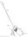
FIG. 1 is a front perspective view of a wheeled scooper according to an exemplary embodiment of the present invention;
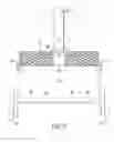
FIG. 2 is a side view of the wheeled scooper of FIG. 2; and
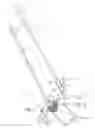
FIG. 3 is a detailed rear view of the wheeled scooper of FIG. 1, illustrating shaft rotation.
DETAILED DESCRIPTION OF THE INVENTION
The following detailed description is of the best currently contemplated modes of carrying out exemplary embodiments of the invention. The description is not to be taken in a limiting sense, but is made merely for the purpose of illustrating the general principles of the invention, since the scope of the invention is best defined by the appended claims.
Broadly, an embodiment of the present invention provides a wheeled scooper that reduces the time and effort needed in collecting, transporting and dumping materials. The scooper provides an elongated handle that may be transversely and forwardly pivotably connected to a collector member. The collector member may provide a front opening to a collection space defined by a front edge. The scooper may provide a set of wheels rotatably mounted near a lower rear portion of the collector member so that a user can control the elongated handle to steer the scooper over a supporting surface and easily scoop, transport and dump material into its collection space by means of the positionable front edge.
Referring now to FIGS. 1 through 3, a scooper 10 can include an elogated handle 12 connected to a collector 20. A grip 14 can be disposed on the end of the handle 12, opposite the collector 20. The handle 12 can be made from various materials, such as wood, metal, fiberglass, composite, or the like. The handle 12 can typically be from about 36 to about 60 inches long, usually about 42 to about 48 inches long.
The handle 12 can attach to a top back side of the collector 20 by various means. For example, as shown in the Figures, a handle receiver can extend from the collector 20 to receive the handle 12. The handle receiver may be an angled plate 24 extending from a rear portion of the collector 20 to connect to the handle 12. The angled plate 24 may help stabilize the collector 20 with stabilizer clips 26 that link the upper portions of the collector 20 and the angled plate 24, as illustrated in FIG. 1. The angled plate 24 may establish a forward pivot point between the handle 12 and the collector 20 for pivoting the collector 20. A shaft pivot pin 28 can be inserted through the handle receiver and the handle 12, securing the handle 12 to the collector 20 and allowing the handle 12 to pivot from side to side, as shown in FIG. 3. The shaft pivot pin 28 may establish a transverse pivot point between the handle 12 and the collector 20
The collector 20 may provide a front opening through which material is collected. The front opening allows access to a collection space defined by a back plate 22, opposing sidewalls and lower plate 32, wherein the lower plate 32 provides a front edge 30. The collector 20 can include wheels 18 to traverse along a supporting surface. The wheels may be disposed on each side of the collector 20 and under the lower plate 32 thereof so as to define a predetermined elevation between the lower plate 32 and the supporting surface. The wheels 18 may be mounted to a U-frame 16 or yolk disposed behind or under the collector 20. Of course, various mechanisms for connecting the wheels 18 to the collector 20 are included within the scope of the present invention. The wheels 18 can optionally be removed, allowing the scooper 10 to be used like a conventional scooping device.
In some embodiments, the back plate 22 of the collector 20 can be formed as a mesh. This can be used to, for example, help allow wet materials to drain and may also help reduce the overall weight of the scooper 10. The mesh may also be used to sift a portion of the material within the collector 20. In some embodiments, the back plate 22 can be replaced with a solid piece to form a back wall of the collector 20.
A user can utilize the angled plate 24 and handle 12 to forward pivot the collector 20 to a collecting position, whereby the front edge 30 rotates to the supporting surface or other surface so that the user can push or move material into the collector 20. A small broom may be provided, for example, for moving material to and from the collector 20. Once the material is collected, the handle 12 can be pivoted backward so the front edge 30 may be near or above the predetermined elevation, a transporting position, with the wheels 18 supporting the collector 20. The scooper 10 can then be easily moved about, on its wheels 18. If the user, when wheeling the scooper 10 with or without material, needs to steer the scooper 10, they can easily twist the handle 12 about the traverse pivot point to facilitate the steering of the scooper 10 over the supporting surface.
The collector 20 can be made in various sizes, depending upon application. For example, the collector can be from about 12 to about 36 inches wide and from about 12 to about 36 inches deep. The collector 20 can be made of various materials, such as plastic, composite, metal, or the like.
A method of using the present invention may include the following. The scooper 10 disclosed above may be provided. A user may wheel the scooper 10 from its stored location to the location of material to be collected and then pivot the collector 20 so its front edge 30 is approximately flush with the surface supporting such material so as to scoop the material into the collection space. Then raising the front edge 30 to the transporting position, the user may direct the scooper 10 to a disposal location for dumping the material. The scooper 10 can be easily dumped in a single smooth motion at the disposal location.
The scooper 10 may be used as a dustpan, pooper scooper, snow shovel, pet litter scooper or the like.
It should be understood, of course, that the foregoing relates to exemplary embodiments of the invention and that modifications may be made without departing from the spirit and scope of the invention as set forth in the following claims.
Claims
What is claimed is:1. An apparatus for collecting, transporting and dumping material, comprising:
an elongated handle member;
a collector member mounted on a lower end of the elongated handle member by means of a transverse and forward pivotal connection, and wherein the collector member provides a lower plate, opposing sidewalls and a back plate that define a collection space; and
a set of wheels rotatably mounted near a lower rear portion of the collector member section.
2. The apparatus of claim 1, wherein the collector member further provides an angled plate extending from near a rear portion of the lower plate to facilitate the forward pivotal connection to the elongated handle member.
3. The apparatus of claim 2, wherein the angled plate further provides a shaft pivot pin enabling the transverse pivotal connection of the lower end of the elongated handle thereto.
4. The apparatus of claim 2, wherein the angled plate further provides a plurality of stabilizer pins interconnecting a distal portion of the angled plate to an upper portion of the collector member,
whereby stabilizing the collector member relative to the lower end of the elongated handle.
5. The apparatus of claim 1, wherein the back plate forms a mesh.
6. The apparatus of claim 1, wherein the elongated handle member ranges in length from about 36 to about 60 inches long.
7. The apparatus of claim 1, wherein the set of wheels are configured to be easily removed,
whereby the remaining apparatus forms a conventional scooping device.
8. An apparatus for collecting, transporting and dumping material, comprising:
an elongated handle member;
a collector member comprising:
a collection space defined by a lower plate, opposing sidewalls and a back plate; and
an angled plate extending from near a rear portion of the lower plate for enabling a forward pivotal connection to the elongated handle member, wherein the angled plate further provides a shaft pivot pin interconnecting the angled plate and the handle member for enabling a transverse pivotal connection thereto, and wherein a plurality of stabilizer pins interconnect a distal portion of the angled plate to an upper portion of the collector member; and
a set of wheels rotatably mounted on a near a lower rear portion of the collector member section, wherein the set of wheels are configured to be easily removed.
9. The apparatus of claim 8, wherein the back plate forms a mesh.
Images & Drawings included:
Sources:
- United States Patent and Trademark Office - verify current appl. status at the USPTO↗
Recent applications in this class:
- » 20250169463 2025-05-29
PET TOILET - » 20250169462 2025-05-29
PET TOILET - » 20250169461 2025-05-29
Pretty Kitty Litter Mat - » 20250160294 2025-05-22
PET TOILET SYSTEM - » 20250134059 2025-05-01
PET TOILET AND CONTROL METHOD THEREOF - » 20250134058 2025-05-01
PET TOILET AND CONTROL METHOD THEREOF - » 20250113800 2025-04-10
INTELLIGENT CAT LITTER BOX - » 20250113799 2025-04-10
ANIMAL LITTER BOX AND FEEDER - » 20250113798 2025-04-10
PET TOILET - » 20250098629 2025-03-27
PET TOILET AND CONTROL METHOD THEREOF