Skin component for a vehicle
US20150147536A1
2015-05-28
14/550,480
2014-11-21
✅ Patent granted
US 9,623,638 B2
2017-04-18
-
-
Catherine A Simone
Lorenz & Kopf, LLP
2035-01-23
Abstract:
A skin component for a vehicle for use as a roof module, an engine compartment hood or a trunk lid is disclosed. The skin component includes at least one supporting layer and a protective layer. The protective layer includes a fiber-reinforced band that is installed along at least one outer edge of the skin component.
Inventors:
- Dirk LUNGERSHAUSEN 6 🇩🇪 Wiesbaden, Germany
- Tino Jacob 2 🇩🇪 Leipzig, Germany
- Dirk Lungershausen 1 🇺🇸 Wiesbaden, DE, United States
Assignee:
- GM GLOBAL TECHNOLOGY OPERATIONS LLC 17,253 🇺🇸 Detroit, MI, United States
Applicant:
Interested in similar patents?
Get notified when new applications in this technology area are published.
Classification:
B62D29/04 » CPC main
Superstructures, characterised by the material thereof predominantly of synthetic material
B29C70/48 » CPC further
Shaping composites, i.e. plastics material comprising reinforcements, fillers or preformed parts, e.g. inserts comprising reinforcements only, e.g. self-reinforcing plastics; Shaping operations therefor; Shaping or impregnating by compression not applied for producing articles of definite length, i.e. discrete articles using matched moulds, e.g. for deforming sheet moulding compounds [SMC] or prepregs and impregnating the reinforcements in the closed mould, e.g. resin transfer moulding [RTM], e.g. by vacuum
B32B27/12 » CPC main
Layered products comprising synthetic resin next to a fibrous or filamentary layer
B29L2009/00 » CPC further
Layered products
B29C70/088 » CPC further
Shaping composites, i.e. plastics material comprising reinforcements, fillers or preformed parts, e.g. inserts comprising reinforcements only, e.g. self-reinforcing plastics; Fibrous reinforcements only comprising combinations of different forms of fibrous reinforcements incorporated in matrix material, forming one or more layers, and with or without non-reinforced layers and with one or more layers of non-plastics material or non-specified material, e.g. supports
B32B7/00 IPC
Layered products characterised by the relation between layers; Layered products characterised by the relative orientation of features between layers, or by the relative values of a measurable parameter between layers, i.e. products comprising layers having different physical, chemical or physicochemical properties; Layered products characterised by the interconnection of layers
B62D29/043 » CPC further
Superstructures, characterised by the material thereof predominantly of synthetic material Superstructures
B29K2101/10 » CPC further
Use of unspecified macromolecular compounds as moulding material Thermosetting resins
B29K2301/12 » CPC further
Use of unspecified macromolecular compounds as reinforcement Thermoplastic materials
B29K2305/00 » CPC further
Use of metals, their alloys or their compounds, as reinforcement
B29L2031/30 » CPC further
Other particular articles Vehicles, e.g. ships or aircraft, or body parts thereof
B32B2260/021 » CPC further
Layered product comprising an impregnated, embedded, or bonded layer wherein the layer comprises an impregnation, embedding, or binder material; Composition of the impregnated, bonded or embedded layer Fibrous or filamentary layer
B32B2260/046 » CPC further
Layered product comprising an impregnated, embedded, or bonded layer wherein the layer comprises an impregnation, embedding, or binder material; Impregnation, embedding, or binder material Synthetic resin
B32B2262/02 » CPC further
Composition or structural features of fibres which form a fibrous or filamentary layer or are present as additives Synthetic macromolecular fibres
B32B2262/06 » CPC further
Composition or structural features of fibres which form a fibrous or filamentary layer or are present as additives Vegetal fibres
B32B2262/101 » CPC further
Composition or structural features of fibres which form a fibrous or filamentary layer or are present as additives; Inorganic fibres Glass fibres
B32B2262/103 » CPC further
Composition or structural features of fibres which form a fibrous or filamentary layer or are present as additives; Inorganic fibres Metal fibres
B32B2262/106 » CPC further
Composition or structural features of fibres which form a fibrous or filamentary layer or are present as additives; Inorganic fibres Carbon fibres, e.g. graphite fibres
Y10T428/24752 » CPC further
Stock material or miscellaneous articles; Structurally defined web or sheet [e.g., overall dimension, etc.] Laterally noncoextensive components
B29C70/08 IPC
Shaping composites, i.e. plastics material comprising reinforcements, fillers or preformed parts, e.g. inserts comprising reinforcements only, e.g. self-reinforcing plastics; Fibrous reinforcements only comprising combinations of different forms of fibrous reinforcements incorporated in matrix material, forming one or more layers, and with or without non-reinforced layers
B32B5/26 » CPC further
Layered products characterised by the non- homogeneity or physical structure, i.e. comprising a fibrous, filamentary, particulate or foam layer; Layered products characterised by having a layer differing constitutionally or physically in different parts characterised by the presence of two or more layers which are next to each other and are fibrous, filamentary, formed of particles or foamed one layer being a fibrous or filamentary layer another layer also being fibrous or filamentary
B32B2605/00 » CPC further
Vehicles
Description
CROSS REFERENCE TO RELATED APPLICATION
This application claims priority to German Patent Application No. 102013019677.9 filed Nov. 22, 2013, which is incorporated herein by reference in its entirety.
TECHNICAL FIELD
The present disclosure relates to a skin component for a vehicle, particularly a roof module, an engine compartment hood or a trunk lid of a composite material that includes a thermosetting polymer matrix, at least one supporting layer of reinforcing fibers and a protective layer.
BACKGROUND
Plastic parts or composite material parts with a plastic matrix are increasingly utilized for skin panels of vehicles. If composite materials with a thermosetting polymer matrix and high-strength reinforcing fibers are used for stability reasons, a severe impact during an accident may cause the parts to fracture. Large sharp-edged, slab-shaped fragments may be created in such instances. Splinter protection films are occasionally applied onto the skin panels in order to prevent these sharp fracture edges. However, this can lead to problems with respect to the adhesion and the optical appearance.
WO 2010/006718 A1 describes a skin component of plastic, for example, a roof module, in which the splinter protection lies between the layers of the roof structure. The skin component includes a first supporting layer, a splinter protection fabric, a core layer, a second supporting layer, a splinter protection fabric, a decoupling layer and a skin. The connection between the individual layers is produced in a CMS process. The structure of the skin component with a plurality of layers and the connection between the layers by means of a CMS process are elaborate and expensive.
SUMMARY
In accordance with the present disclosure, skin components of plastic, particularly of composite materials, can be designed in such a way that an effective splinter protection can be realized with little effort. According to an embodiment of the present disclosure, a skin component for a vehicle includes at least one supporting layer and one protective layer. The protective layer includes a fiber-reinforced band that is installed along at least one outer edge of the skin component. The band provides effective protection against mechanical stresses that originate from the edge of the skin component with little material input. In contrast to fabric webs that cover the entire surface of the skin component, scrap can almost be completely eliminated. The total quantity of fibers used for the protective layer therefore is so small that the overall skin component can also be cost-effectively manufactured if expensive high-quality fibers are used in the protective layer.
The fibers of the protective layer may be arranged between two supporting layers. In this way, a stable integration of the protective layer into the skin component is achieved and the component surface is not optically affected. The fibers of the protective layer may include a pre-stretched thermoplastic polymer or steel. Fabrics can be subjected to high stresses in the intact state, but once damage has occurred under a load and initial fibers have been torn, the fibers extending transverse to the torn fibers cause a concentration of the load on a small area and thusly promote a propagation of the tear. The fibers of the protective layer may not be interwoven in order to prevent such a load concentration. The fibers may be oriented, in particular, in the longitudinal direction of the band in order to divert a load along the edges of the skin component without tearing.
The band may be impregnated with a thermosetting polymer matrix of the at least one supporting layer after the completion of the skin component. This can be achieved, in particular, with a loose band of fibers that are not connected to one another. It is more convenient to install a band, the fibers of which are held together by being embedded in a separate matrix or carrier layer of the band. Such a matrix may be fused together with a thermosetting polymer matrix of the at least one supporting layer after the completion of the skin component.
The supporting layer may likewise be reinforced with fibers, but the requirements with respect to the strength of these fibers are not as strict as with the fibers of the protective layer and this can be taken into account in the concentration of the fibers in the matrix, their length and/or their chemical composition. The fibers of the supporting layer may consist, in particular, of carbon fibers, glass fibers or natural fibers of plant origin. The fibers of the supporting layer may be structured in the form of a fabric in order to simplify their handling during the manufacture of the skin component. The fibers of the supporting layer may be pre-impregnated (prepreg fibers). The manufacture of the skin component may be realized by means of infiltration of the supporting layer and the protective layer with a thermosetting polymer matrix, by means of resin-transfer-molding (RTM) processes or by means of gap impregnation. In this way, the fibers of the protective layer are completely enclosed by the matrix.
BRIEF DESCRIPTION OF THE DRAWINGS
The present disclosure will hereinafter be described in conjunction with the following drawing figures, wherein like numerals denote like elements, and:
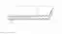
FIG. 1 shows a perspective view of the upper part of a vehicle with a roof module; and
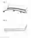
FIG. 2 shows a detail of the roof module in the region of the outer edge.
DETAILED DESCRIPTION
The following detailed description is merely exemplary in nature and is not intended to limit the present disclosure or the application and uses of the present disclosure. Furthermore, there is no intention to be bound by any theory presented in the preceding background or the following detailed description.
FIG. 1 shows a perspective view for part of the roof area of a car body. A roof frame 2 includes lateral profiles that extend above the doors on the right and the left side of the vehicle and connect A-columns and C-columns to one another, as well as front and rear cross members 3, 4. FIG. 1 only shows one of the two lateral profiles. The front cross member 3 extends underneath the roof module 1 adjacent to a front windshield as indicated with a broken line; the rear cross member 4 extends underneath the rear edge of the roof module 1.
The roof module 1 is a composite component including several layers. It includes at least one supporting layer that extends over the entire roof module 1, as well as a protective layer 11 that extends along the edge of the roof module 1 in the form of a strip, but not over the center of the roof module 1.
In the embodiment according to FIG. 1, a strip of the protective layer 11 extends along a left outer edge 6 of the roof module 1 that faces the viewer as shown and a second strip extends along the right outer edge that is not illustrated in FIG. 1. These are the outer edges that are in contact with the profiles 5 and therefore most fracture-prone in an accident. Other not-shown strips of the protective layer 11 may be provided on the front and rear edges of the roof module 1.
FIG. 2 shows a schematic cross section through the roof module 1 in the vicinity of the outer edge 6. In this case, the roof module 1 includes two supporting layers 8, 9 that directly contact one another in a central region of the roof module 1, wherein the protective layer 11 extends between these two supporting layers adjacent to the edge.
The first and the second supporting layer 8, 9 respectively include a fabric 13, the threads of which includes high-strength carbon fibers, glass fibers and/or plant fibers. The fabric 13 could also be replaced with a formed fabric of unspun fibers. The fabric 13 is embedded in a thermosetting polymer matrix 12. An epoxy resin, a polyester resin or a polyurethane, in particular, may be considered as thermosetting polymer of the matrix 12.
In this case, the protective layer 11 includes fibers 14 that are aligned parallel to the edge 6. These fibers 14 were originally placed between the fabrics 13 of the supporting layers 8, 9 without being firmly connected to one another, e.g. in the form of a longitudinally combed formed fabric, and then impregnated with the thermosetting polymer matrix 12 together with the fabrics of the supporting layers so as to obtain the roof module 1. In order to simplify the impregnation, the fibers 14 of the protective layer 11, as well as of the supporting layers 8, 9, may be pre-impregnated, i.e. includes so-called prepreg fibers.
The fibers 14 of the protective layer 11 need to have a high elongation at fracture. Consequently, they preferably include a pre-stretched thermoplastic polymer, particularly of polyethylene (PE), polypropylene (PP), polyethylene terephthalate (PET) and/or of a steel.
In order to simplify the installation, the protective layer 11 may in addition to the fibers 14 also contain a band of a carrier material, in which the fibers 14 are embedded or onto which they are glued. The protective layer may particularly include so-called UD-tape. After the impregnation with the matrix 12, the carrier material may be intimately glued or fused thereto such that it cannot be distinguished from this matrix in the illustration in FIG. 2.
Different layer structures are contemplated in the present disclosure, including: a single supporting layer 8; a supporting layer 8 including several fiber fabrics lying on top of one another on at least one side of the protective layer 11; a protective layer 11 respectively realized between several supporting layer is 8, 9; a protective layer 11 formed on the outermost layer of the roof module 1.
If the roof module 1 is subjected to a load that originates from one of the lateral profiles 5 during a side impact, cracks may indeed form in the matrix 12 and fibers or entire threads of the supporting layers 8, 9 may possibly also be destroyed, but the fibers 14 of the protective layer 11 do not break, but rather deform in an elasto-plastic fashion. This prevents propagation of the cracks and the flanks of the cracks are held close to one another. Individual fragments of the roof module 1 cannot separate. This furthermore prevents sharp corners and edges that could protrude from the roof module 1.
Fibers of the protective layer 11 may also be arranged along the outer edge 6 of the roof module 1 along the front and the rear roof frame 3, 4. The composite material structure chosen for the roof module 1 may likewise be used for other skin components such as an engine compartment hood, a trunk lid, fenders and doors. In this case, the fibers of the protective layer 11 extend along the outer edges of the component that are particularly stressed and fracture-prone during an impact due to an accident. However, they may also cover other fracture-prone component areas.
The manufacture of the roof module 1 takes place in the following steps. The fiber fabric 13 of the supporting layer 8 are placed into a mold for the roof module 1. The fibers of the protective layer 11 are placed individually, adjacently or in the form of unidirectional fiber bands such as UD-tapes. The fiber fabric of the second supporting layer 9 are placed thereon. The supporting layers 8, 9 are infiltrated or interwoven with the protective layer 11 with a thermosetting polymer matrix 12 in a resin-transfer-molding (RTM) process or by means of gap impregnation. If a different layer structure is chosen, the placement of the layers 8, 9, 11 into the mold is carried out accordingly prior to the infiltration of the layers.
In a first variation, the fiber fabric of the supporting layers 8, 9 is composed of pre-impregnated fibers (prepreg fibers). The impregnation includes a resin and a hardener that react to form a thermosetting polymer during processing. Preferred thermosetting polymers are epoxy resin, polyester resin or polyurethane. Hot-pressing of the layers in a mold or autoclave causes the impregnation to react, as well as to interfuse and completely enclose the supporting layers 8, 9 and the protective layer 11, such that the matrix 12 is formed.
In a first variation, the manufacture of the roof module 1 takes place in the following steps. The pre-impregnated fiber fabric of the supporting layer 8 are placed into the mold for the roof module 1. The fibers of the protective layer 11 are placed individually, adjacently or in the form of unidirectional fiber bands such as UD-tapes. The impregnated fiber fabric of the second supporting layer 9 are placed thereon. The layers 8, 9, 11 are hot-pressed in the mold or in an autoclave.
While at least one exemplary embodiment has been presented in the foregoing detailed description, it should be appreciated that a vast number of variations exist. It should also be appreciated that the exemplary embodiment is only an example, and are not intended to limit the scope, applicability, or configuration of the present disclosure in any way. Rather, the foregoing detailed description will provide those skilled in the art with a convenient road map for implementing an exemplary embodiment, it being understood that various changes may be made in the function and arrangement of elements described in an exemplary embodiment without departing from the scope of the present disclosure as set forth in the appended claims and their legal equivalents.
Claims
1-12. (canceled)
13. A skin component for a vehicle, comprising at least one supporting layer and a protective layer, wherein the protective layer includes a fiber-reinforced band that is installed along at least one outer edge of the skin component.
14. The skin component according to claim 13, further comprising two supporting layers, wherein the protective layer is arranged between the two supporting layers.
15. The skin component according to claim 13, wherein the fibers of the protective layer comprises at least one of a pre-stretched thermoplastic polymer and steel.
16. The skin component according to claim 13, wherein the fibers of the protective layer are not interwoven.
17. The skin component according to claim 13, wherein the fibers of the protective layer are oriented in a longitudinal direction of the fiber-reinforced band.
18. The skin component according claim 13, wherein the protective layer is a fiber layer impregnated with a thermosetting polymer matrix of the at least one supporting layer.
19. The skin component according to claim 13, wherein the protective layer comprises a matrix fused together with a thermosetting polymer matrix of the at least one supporting layer.
20. The skin component according claim 13, wherein the supporting layer further comprises reinforcing fibers including at least one of a carbon fiber, a glass fiber or a plant-based fiber.
21. The skin component according to claim 20, wherein the reinforcing fibers of the supporting layer comprise a fabric.
22. The skin component according to claim 13, wherein the supporting layer comprises pre-impregnated fibers.
23. The skin component according to claim 13, wherein the skin component comprises one of a roof module, an engine compartment hood or a trunk lid.
24. A method for fabricating a skin component according to claim 13 comprising interweaving the supporting layer and the protective layer with a thermosetting polymer matrix using a resin-transfer-molding (RTM) process.
25. A method for fabricating a skin component according to claim 13 comprising interweaving the supporting layer and the protective layer with a thermosetting polymer matrix using a gap impregnation process.
Images & Drawings included:
Sources:
- United States Patent and Trademark Office - verify current appl. status at the USPTO↗
Similar patent applications:
- » 20180236697
Method of manufacturing a composite skin-foam-carrier component for a motor vehicle and composite skin-foam-carrier component for a motor vehicle - » 20200223157
Method for producing a fiber-reinforced plastic outer skin component for a vehicle, and fiber-reinforced plastic outer skin component - » 20050133958
System and method for coloring a spray urethane skin for vehicle interior trim components and skins made thereby - » 20210024078
Electronic skin for vehicle components - » 20230150582
Outer Skin Component for a Motor Vehicle and Method for Producing an Outer Skin Component - » 20060024507
Method for preparing a spray urethane skin having a clear coat for vehicle interior trim components and skins made thereby - » 20120139294
Motor vehicle having interconnected outer skin components and a method for connecting outer skin components - » 20220324155
METHOD FOR PRODUCING COMPONENTS OF AN OUTER SKIN OF A VEHICLE
Recent applications in this class:
- » 20240199141 2024-06-20
Vehicle body component - » 20240174302 2024-05-30
BODY PANEL ASSEMBLY - » 20230286596 2023-09-14
VEHICLE COMPONENT AND METHOD - » 20230219635 2023-07-13
VEHICLE BODY STRUCTURAL MEMBER - » 20230202584 2023-06-29
REINFORCING ELEMENT FOR REINFORCING A STRUCTURAL ELEMENT - » 20220297768 2022-09-22
Frame which is made of fiber reinforced composite - » 20220194487 2022-06-23
Exterior member for vehicle and method for manufacturing the same - » 20220135144 2022-05-05
VEHICLE STRUCTURE AND METHOD FOR COATING VEHICLE - » 20220081044 2022-03-17
Underbody shield compositions and articles that provide enhanced peel strength and methods of using them - » 20210362787 2021-11-25
BODYWORK PART COMPRISING A BACKLIT ZONE
Recent applications for this Assignee:
- » 20250293679 2025-09-18
PROGNOSIS AND CONTROL OF POWER MODULE FOR ELECTRIC LOAD - » 20250293365 2025-09-18
FIBER-REINFORCED POLYMER BATTERY ENCLOSURES, COMPOSITE COMPONENTS, AND METHODS WITH INTEGRATED POLYMER SEALS - » 20250293279 2025-09-18
MEMBRANE ELECTRODE ASSEMBLY - » 20250293272 2025-09-18
METAL BEAD SEAL BUCKLING LOAD AND PRESSURE UNIFORMITY WITH AN ENFORCEMENT LAYER - » 20250293270 2025-09-18
METHOD OF SHAPING BIPOLAR PLATES - » 20250289417 2025-09-18
DETERMINATION OF EVASIVE MANEUVER ACTION TO AVOID ONCOMING ROAD HAZARD OF A VEHICLE - » 20250289366 2025-09-18
SYSTEM AND METHOD FOR NOTIFYING PASSENGERS OF NEARBY OBJECTS - » 20250286485 2025-09-11
CONTROL CIRCUIT FOR A DIRECT CURRENT MOTOR - » 20250286331 2025-09-11
ELECTRICAL CONNECTOR MOUNTING - » 20250286096 2025-09-11
MEMBRANE ELECTRODE ASSEMBLY HAVING AN ORGANIC SOLVENT