MECHANISM FOR THE SIMULTANEOUS ADJUSTMENT OF GAPS AND/OR THE SIMULTANEOUS ADJUSTMENT OF ANGLES, FOR THE PRODUCTION OF A MULTI-LEVEL OR STAIRCASE STRUCTURE
US20150197948A1
2015-07-16
14/420,425
2013-08-22
Abstract:
The invention relates to a mechanism for the simultaneous adjustment of gaps and/or angles for the production of a multi-level or stair structure. The mechanism is characterised in that it comprises a technical housing containing a gap-indicating rule which is provided with parallel inclined grooves and which moves diagonally on fixed transverse shafts. Said diagonal translational movement, performed by a forward-backward control element, causes the sliding of upper shafts and lower shafts that are interconnected by a series of V-shaped arms. The upper shafts slide in a gap-indicating slide and the lower shafts slide in the slide of the technical housing. The lower shafts are solidly connected to the pendulums bearing the plates, allowing the simultaneous adjustment of the gaps between the plates. The technical housing also contains an angle-indicating rule which is provided with parallel inclined grooves and which moves diagonally on fixed transverse shafts, said diagonal translational movement causing the simultaneous movement of sliders in the angle-indicating slide. The aforementioned sliders also pivot the pendulums via a slide-element located at the front end of the pendulums. The technical housings are secured to the wall or the side support by a mortise-and-tenon system on securing supports. According to the invention, the device is intended in particular for the production of a generally straight staircase or staircase formwork.
Interested in similar patents?
Get notified when new applications in this technology area are published.
Classification:
E04F21/26 » CPC main
Implements for finishing work on buildings for mounting staircases, e.g. tools for marking steps
Description
The field of the invention is that the adjustment devices enabling making of multi-level or staircase structures in a predetermined shape. It enables, in particular, the design of adaptable stairs or stair casing, or the making of multi-level structure requiring an option of simultaneous adjustment of consistently symmetrical gaps and/or variable angle adjustment while maintaining symmetric treads. The invention can also be used in other applications requiring a similar adjustment means such as tracings requiring adjustments of equal angles or spaces in order to make out works such as windows portals grids, but also to set up a series of tools (for drilling, welding, cutting, assembling, distributing . . . } having variable, but consistently symmetrical, gaps; the usage list is not exhaustive.
Hitherto, mobiles processes for making such structures are artisanal in nature. The professional (mason, carpenter, blacksmith . . . ) successively measures and traces each tread and riser on opposing stair stringboards. This work is not only time-consuming but subject to numerous errors: line thickness, rules slope, eye approximations, support of varying coarseness . . . ; these traditional methods can cause asymmetry problems of varying treads.
To remedy this a solution is proposed by the patent FR Number 01 04147 via a so-called screw-nut technology. The system enables simultaneous adjustment of the spaces or the angles between the riser pendulums. Given the friction generated by the screw-nut links guiding then, the force to be provided in order to set in motion a series of adjustments is such that the system locks up as soon as 3 screw-nuts are exceed and renders this technology unworkable for this kind of application.
An alternative is also proposed by the U.S. Pat. No. 2,883,759. This solution includes a device for riser positioning via two parallel screw mechanisms. One enables adjustment of spaces by a parallelogram mechanism controlled at the end by a screw that varies the space between two profiles, which deploys a double bar. Another mechanism enables management of the separation between these parallel bars in order to incline the risers connected to the two. This device is not suitable for practice by virtue of minimalism of these controls. It has considerable friction that cannot be compensated by a simple actuation of controls. With the exhibition of problems such as dust—water—sand . . . , this system appears too fragile and prone to inopportune lockups.
The objective of the invention discussed in this patent is thus innovative in that it is a simple method using sliding of shafts in slides, without screw system or the mechanical adjusting part, is completely contained in a mechanical housing which increases reliability; adaptable to all straight steps. It can also be used for making winding or spiral staircases; it is also easily and intuitively useable by the user while being manually transportable.
The mechanical system according to the invention comprises:
1) Mechanism for the simultaneous adjustment of gaps and/or angles for making a multi-level or staircase structure, characterized in that it comprises:
A—a mechanical housing (1.1) comprising, at its base, a longitudinal slide (1.2) and a longitudinal channel (1.4) in which the pendulums (5.1) slide and also transverse fixed axels (1.6) longitudinally aligned at the center of the aforementioned mechanical housing (1.1)
B—a gap-indicating rule (2.1) comprising a gap slide (2.2) having parallel oblique grooves (2.3) and a forward-backward control (2.4) provided with a locking means (2.5)
C—an angle-indicating rule (3.1) comprising an angle slide (3.2) having parallel oblique grooves (3.3) and a forward-backward control (3.4) provided with a locking means (3.5)
D—arms (4.1) hinged at one of their ends (4.2) by the lower shafts (4.4) slidable in the aforementioned longitudinal slide (1.2) of the aforementioned mechanical housing (1.1) and hinged at the other end (4.3) by the upper shafts (4.5) which slide in the aforementioned gap slide (2.2) thus forming a succession of the aforementioned arm (4.1) V-shaped hinged with an angle that is variable while maintaining the aforementioned arms (4.1) symmetric
E—the aforementioned pendulums (5.1) which each have a bore (5.2) traversed by the aforementioned lower shafts (4.4) and a slide (5.3) traversed by a slider (5.4) which moves in the aforementioned angle slide (3.2)
2) Adjustment mechanism characterized in that the gap-indicating rule (2.1) moves by sliding of the parallel oblique grooves (2.3) on the transverse fixed axels (1.6) of the mechanical housing (1.1) which generates a diagonal translation of the aforementioned gap-indicating rule (2.1) relative to the axis of the aforementioned mechanical housing (1.1).
3) Adjustment mechanism characterized in that the gap-indicating rule (2.1) is provided with a forward-backward control (2.4) enabling the aforementioned gap-indicating rule (2.1) to drive the diagonal translation which generates a change in space between the aforementioned gap-indicating rule (2.1) and the longitudinal slide (1.2) of the mechanical housing (1.1) while maintaining their parallelism.
4) Adjustment mechanism characterized in that the variation of space driven by the forward-backward control (2.4) of the gap-indicating rule (2.1) generates a simultaneous movement of the lower shafts (4.4) in the longitudinal slide (1.2) and a simultaneous movement of the upper shafts (4.5) in the gap slide (2.2) causing a simultaneous change of the gaps between the aforementioned upper shafts (4.5) and a simultaneous change of the gaps between the aforementioned lower shafts (4.5) attached to the pendulums (5.1), while complying with their symmetry.
5) Adjustment mechanism characterized in that any one of the lower shafts (4.4) can have the function of reference fixed shaft (1.3) by attaching the aforementioned fixed shaft (1.3) to the mechanical housing (1.1) wherein the aforementioned fixed shaft (1.3) is the basis for the simultaneous movement of the other lower shafts (4.4) as well as the simultaneous movement of the upper shafts (4.5) at the time of the diagonal translation of the gap-indicating rule (2.1).
6) Adjustment mechanism characterized in that the angle-indicating rule (3.1) moves by sliding of parallel oblique grooves (3.3) on the transverse fixed axels (1.6) of the mechanical housing (1.1) which generates a diagonal translation of the aforementioned angle-indicating rule (3.1) relative to the axis of the aforementioned mechanical housing (1.1).
7) Adjustment mechanism characterized in that the angle-indicating rule (3.1) is provided with a forward-backward control (3.4) enabling the aforementioned angle-indicating rule (3.1) to have a diagonal translation that generates a variation of space between the aforementioned angle-indicating rule (3.1) and the longitudinal slide (1.2) of the mechanical housing (1.1) while maintaining their parallelism.
8) Adjustment mechanism characterized in that following its positioning by human action, the variation of the space between the angle-indicating rule (3.1) and the longitudinal slide (1.2) of the mechanical housing (1.1) causes a simultaneous change of the angle of the pendulums (5.1) by displacement of the sliders (5.4) in the angle slide (3.2) which creates a rotation of the slides (5.3) about the lower shafts (4.4) attached to with the aforementioned pendulums (5.1).
9) Adjustment mechanism including a main significant feature is that each pendulum (5.1) has, in its part outside of the mechanical housing (1.1), a profile arranged with notches (5.9) and with attachment holes (5.8) for attaching it to a plate (5.6) provided with fins (5.7) that slide in the aforementioned notches (5.9) holding the aforementioned plate (5.6) thus locked on the aforementioned pendulum (5.1) and that the aforementioned attachment holes (5.8) are used for the passage of screws or spikes for the attachment of the aforementioned plate (5.6) wherein the aforementioned plate (5.6) can be a walk or a riser or any other support according to the configuration of the structure to be made.
10) Adjustment mechanism characterized in that the mechanical housing (1.1) can be attached to a lateral support by attachment mounting plates (7.1) provided with a tenon (7.3) that receives a mortise (5.5) of the pendulum (5.1) wherein other attachment means (8.1) are located on the end caps of the mechanical housing (1.1) and that the aforementioned attachment mounting plates (7.1) or the aforementioned other attachment means (8.1) can be used according to the configuration of the structure to be made.
11) An adjustment mechanism mainly characterized in that the pendulums (5.1) have a notch (6.2) for holding and pulling an elastic sealing means (6.1) of the longitudinal slit (1.4) wherein the aforementioned elastic sealing means (6.1) is located in a casing (1.5) at the base of the mechanical housing (1.1).
12) Adjustment mechanism characterized in that the mechanical housing (1.1) can be used individually or multiple mechanical housings (1.1) can be used in parallel or in extension, according to the configuration of the structure to be made.
For complementarity of explanation, the invention comprises:
A—a mechanical housing comprising:
-
- a longitudinal slide: a slide comprises two grooves facing each other along the length of the housing, in which slide the ends of lower shafts
- a longitudinal groove that enables the pendulums with plates to move in a translation caused by the gap-indicating rule or an angle variation caused by the angle-indicating rule; the plates can be steps or risers, or different connecting members transmitting simultaneous adjustments from the housing
- a casing for guiding an elastic sealing means: this elastic means has a function of sealing the longitudinal groove in order to protect the inside of the mechanical housing from any materials that can damage the operation of the mechanism; it is penetrated by each pendulum through a suitable slit; each pendulum having a notch that maintains the elastic means secured to the pendulum
- transverse axels attached to the mechanical housing distributed on a longitudinal line to different locations designed to enable the movement of the oblique grooves without hindering the movement of the arms; these fixed axels have a function of guiding the parallel oblique grooves of the gap-indicating rule and, independently, of the angle-indicating rule during at their respective translation
B—a gap-indicating rule positioned in the mechanical housing and comprising:
-
- a gap slide: this slide comprises two longitudinal grooves facing each other in which slide the ends of the upper shafts
- parallel oblique grooves that slide on the fixed axes of the mechanical housing during the translation of the gap-indicating rule; these grooves being positioned oblique with respect to the axis of the housing, this enables the gap-indicating rule to move diagonally in the housing; this diagonal movement, during the translation, causes the gap-indicating rule, when it is in the upper part of the housing, to steer gradually towards the lower part while steering towards one end of the housing. This diagonal translation generates a simultaneous movement of upper shafts in the gap slide and lower shafts in the longitudinal slide; the lower shafts drive the pendulums and simultaneously vary their spaces; the parallel oblique grooves are distributed at various locations of the gap-indicating rule corresponding to the transverse fixed axels of the mechanical housing, so as not to impede the movement of arms
- a forward-backward control to cause the diagonal translation of the aforementioned gap-indicating rule, which generates a simultaneous adjustment of the gaps between the different shafts that remain consistently symmetrical; this control has a locking means that enables immobilization of the gap-indicating rule at the desired adjustment
C—an angle-indicating rule positioned in the mechanical housing and comprising:
-
- an angle slide: this slide comprises two longitudinal grooves facing each other in which slide the ends of the sliders during the translation of the angle-indicating rule
- parallel oblique grooves that slide on the fixed axels of the mechanical housing during the translation of the diagonal angle-indicating rule; these grooves being positioned oblique by with respect to the axis of the housing. This enables the angle-indicating rule to move diagonally in the housing. This diagonal movement, during translation, causes the angle-indicating rule, when the upper part of the housing, to steer gradually towards the lower part while steering towards one end of the housing according to the angle setting to be effectuated; these oblique grooves are distributed in different locations of the angle-indicating rule corresponding to the transverse fixed axels of the mechanical housing so as not to hinder the movement of the arms
- a forward-backward control for causing translation of the aforementioned angle-indicating rule, which generates a simultaneous adjustment of the angle of the pendulums while maintaining them symmetrical
D—arms: this are elongate flat elements with bores for being interconnected between themselves at one end by a lower shaft that slides in the longitudinal slide of the mechanical housing, and at the other end by the upper shafts that slide in the gap slide; these joints thus form a succession of V-shaped arms having an angle that is variable but consistently symmetrical
E—pendulums having:
a—a part inside of the housing, on which are located:
-
- a bore penetrated by the lower shafts by which they are secured in their translation movements
- a slide traversed by a slider that moves in the angle slide
- a notch to hold and pull an elastic means for sealing. This elastic means has a function of preventing penetration into the housing or of liquid or materials; it is penetrated by the pendulums through a slit for each pendulum and tightens or relaxes over the course of movement of the pendulums; the pendulums traversing the longitudinal groove of the mechanical housing in order to transmit the internal adjustment of the aforementioned mechanical housing to the plates.
b—a part outside of the housing, which transmits the adjustments of the gap-indicating and/or angle-indicating rules to the various plates, on which are located:
-
- notches enabling locking or attaching of tread or riser or staircase plates
- a mortise capable of receiving the tenon of a support mounting plate for the installation of the housing on a wall or on any lateral member
- a façade having holes for attaching planks of all kinds: steps, risers, shelves, tools . . . ; this list is not exhaustive of possible applications.
These various mechanical elements are combined to achieve the adjustment of gaps first and independently of the complementary adjustment of angle of the following different ways:
-
- The gap-indicating rule and the angle-indicating rule are each provided with parallel oblique grooves enabling a diagonal translation in the housing by sliding of the aforementioned parallel oblique grooves on the transverse fixed axels of the housing.
- The gap-indicating rule is provided with a forward-backward control enabling the aforementioned gap-indicating rule to have a diagonal translation that varies the space between the aforementioned gap-indicating rule and the slide of the mechanical housing while maintaining their parallelism; this variation spaces of generates a simultaneous movement of the lower shafts in the longitudinal slide in the mechanical housing and upper shafts in the slide gap-indicating of the gap-indicating rule which simultaneously changes the gaps between the upper shafts and the gaps between the aforementioned lower shafts in secured to with the pendulums while respecting their symmetry.
- A reference fixed shaft serves as basis for the simultaneous movement of the lower shafts and upper shafts wherein each of the lower shafts can become reference shaft by attaching to the mechanical housing and each of the aforementioned upper shafts can become reference shaft by attaching to the angle-indicating rule; there can be only one reference shaft on the entirety mechanism and it can be located at end or in the center or on any shaft.
- The angle-indicating rule is provided with a forward-backward control enabling the aforementioned angle-indicating rule to have a diagonal translation that varies the space between the aforementioned angle-indicating rule and the longitudinal slide of the mechanical housing while maintaining their parallelism; the change of space between the angle slide of the angle-indicating rule and the longitudinal slide of the mechanical housing generates a simultaneous change of the angle of the pendulums by displacement of the sliders in the aforementioned angle slide causing a rotation of the slide about the bore of the pendulums penetrated by the lower shafts.
- The forward-backward controls of the gap-indicating rule and of the angle-indicating rule are provided with a desired setting locking means in order to block any inopportune movement in translation specific to each rule.
- Mounting plates for attachment to a lateral support or a wall are designed to receive the pendulums via a mortise and tenon system in addition to other attachment means that are located on the plugs of the ends of the mechanical housing; depending on the situations, this can be the mortise and tenon system or attachment means joined to the plugs that can be used or both means jointly.
- Each pendulum has, in its part outside of the mechanical housing, a profile arranged with notches in order to hold there a plate provided with fins that hold the aforementioned plate thus locked on the pendulum wherein the plate can be a step or riser or other elements or members according to the use for which the mechanism is used. Each support also has, in its part outside of the mechanical housing, an L-shaped facade having holes for attaching the plate either by screws or any suitable means
Furthermore, at its center, each pendulum has a notch for holding and pulling an elastic sealing means for the longitudinal channel, the elastic sealing means being located in a casing at the base of the mechanical housing; the elastic means can be a rubber seal that tightens and relaxes over the course of the movements wherein the rubber has a notch for allowing the pendulum to pass and that the rubber follows the movement of the aforementioned support; the elastic sealing means can also be a succession of metal strips each secured to a pendulum, the strips overlapping at their end
The present invention will be better understood by reference to the description and to the claims by drawings showing the system in its different operations:
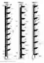
FIG. 1 is a longitudinal section of the mechanical housing (1.1) in superposition with a longitudinal section of the gap-indicating rule (2.1); this assembly shows the principle of the arms (4.1) of which one end is connected to another arm (4.1) by a lower shaft (4.4) that slides in the longitudinal slide (1.2) of the mechanical housing (1.1) and the other end is connected to another arm (4.1) by an upper shaft (4.5) that slides in the gap slide (2.2); there is shown arms (4.1) in substantially at right angle position, with the gap-indicating rule (2.1) which is located further away from the longitudinal slide (1.2) and the fixed axels (1.6) at one end of the oblique groove; the reference fixed shaft being central in this presentation the pendulum having ends distant from the ends of the mechanical housing is shown.
FIG. 2 is a longitudinal sectional view of the mechanical housing (1.1) in superposition with a longitudinal section of the gap-indicating rule (2.1) as in FIG. 1, but with a different adjustment caused by a diagonal translation; thus it can be noted that the gap-indicating rule (2.1) is closer to the longitudinal groove (1.4) and that the fixed axels (1.6) are at the other end of the parallel oblique grooves; it can also be noted that the end pendulums are moved closer to the ends of the mechanical housing due to the reference fixed shaft (1.3) is central in this presentation; the gap-indicating rule (2.1) is also brought closer to one end of the mechanical housing (1.1) due to the diagonal translation caused by the forward-backward control (2.4); the gaps between the pendulums are further apart there than in FIG. 1 due to the deployment of arms (4.1) caused by the diagonal translation.
FIG. 3 is a longitudinal sectional view and in superposition:
-
- of the mechanical housing (1.1)
- the angle-indicating rule (3.1) or is seen the pendulum penetrated at the bore by the lower shaft (4.4) which slides in the longitudinal slide; also seen there is the slider (5.4) which moves in the angle slide (3.2) by rotation of the slide (5.3) about the lower shaft (4.4) during a translation of the angle-indicating rule (3.1), which generates a variation of the angle of the pendulums (5.1)
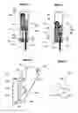
FIG. 4 is a cross-sectional view of the mechanism assembly in which is seen the mechanical housing (1.1) with:
-
- at the base the longitudinal slit (1.4) penetrated by the pendulum (5.1) which passes through it the elastic sealing sealing means (6.1) guided by its casing (1.5); at the center is seen a fixed axel (1.6) on which slide, to the left of the gap-indicating rule (2.1), and to the right of the angle-indicating rule (3.1)
- the gap-indicating rule (2.1) is positioned in the upper part of the mechanical housing (1.1) which translates through a more retracted position of the arms (4.1) as in FIG. 1; on the gap-indicating rule is seen the gap slide (2.2) or slide the upper shafts (4.5) connecting the arms (4.1); the arms steer downward in the mechanical housing (1.1) in order to be connected by the lower shafts (4.4)
- the angle-indicating rule (3.1) receives, at its base, the upper part of the pendulum (5.1) which translates through a more open angle of the positioning of the pendulum (5.1), in its part outside of the mechanical housing, by the rotation of the pendulum (5.1) about the lower shaft (4.4) through the bore (5.2)
FIG. 5 is a view similar to FIG. 4 with the differences that the gap-indicating rule (2.1) and the angle-indicating rule (3.1) are in low position in the mechanical housing (1.1) as in FIG. 2 with the mechanical changes as described in FIG. 2.
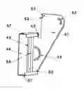
FIG. 6 is a view of a pendulum (5.1) with:
-
- the inner part of the housing which comprises the bore (5.2) designed to be traversed by the lower shaft (4.4), the slide (5.3) designed to be traversed by the slider (5.4), the notch provided for holding the elastic sealing means (6.1)
- the part outside of the housing with the notches (5.9) receiving the fins (5.7) of the plate (5.6); also seen is the mortise (5.5) provided for the tenon (7.3) of the support mounting plate (7.1); on the widest part receiving the plate is seen a return of the pendulum with holes (5.8) for attaching the plate (5.6) by means of screws or spikes, according to the material used
FIG. 7 shows the support mounting plate (7.1) for attachment of the mechanical housing (1.1) with the tenon (7.3) arranged with the mortise (5.5) of the pendulums (5.1) and holes (7.2) for screwing or nailing on a wall or a lateral support.
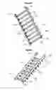
FIG. 8 shows a perspective of a setup of two mechanicals housings (1.1) connected in parallel with the plates (5.6) in treads position, in the configuration of a straight staircase.
FIG. 9 shows a perspective of a setup of two mechanicals housings (1.1) connected by parallel plates (5.6) in risers position, in the configuration of a straight staircase casing.
Implementation of making a straight flight of stairs having 9 steps (FIG. 8):
The trace of the first and last tread and riser are made on a wall (or lateral support):
-
- An attachment mounting plate is fixed on each trace (1st and 9th) at the angle of the tread.
- The tracing is reproduced on the other lateral wall.
- The attachment mounting plates are attached on the 1st and the 9th tread on the second lateral wall.
- The mechanical housing is taken and the mortise of the first pendulum is hooked hanged on the pin of a base mounting plate (first tread).
- The forward-backward control of the gap-indicating rule is manipulated until the mortise of the 9th tread matches the tenon of the attachment mounting plate of the 9th tread
- The control is locked by its locking means.
- Additionally the housing is attached by the attachment means secured to the plugs
- The pendulums attached to the attachment mounting plates are automatically manipulated by the angle-indicating rule; it can be manipulated by means of the control of the rule which is subsequently locked.
- Exactly the same maneuvers are reproduced on the second lateral wall.
- The plates are introduced successively by sliding them into the notches of the pendulums; these plates can be elements sliding into one another in order to instantly adjust the plates to the width of the stairs; the plates can be attached to the hole means in the facade of the pendulums with screw nuts or spikes, according to the material used for the plates.
The staircase structure is thus made!
The invention is applicable to many other uses than the steps of straight staircases and is capable of different variants of execution, including:
-
- The mechanism can be used to make structures or traces requiring equal spaces such as balusters, railings, gates, staircases of all kinds in various materials.
- The mechanism can be used to make adjustable shelving or any other movable or non-movable structure
- The mechanism can be used as a base structure for adjusting successive tools for drilling, cutting, welding or any other similar application,
- The mechanism can be adapted to agricultural or industrial machines of all types requiring a space or angle adjustment.
This list is not exhaustive of all use possibilities of the invention.
Claims
1. Mechanism for simultaneous adjustment of gaps and/or angles for making a multi-level or staircase structure, characterized in that it comprises:
A—a mechanical housing comprising, at its base, a longitudinal slide and a longitudinal channel in which the pendulums slide and also transverse fixed axels longitudinally aligned at the center of the aforementioned mechanical housing
B—a gap-indicating rule comprising a gap slide having parallel oblique grooves and a forward-backward control provided with a locking means
C—an angle-indicating rule comprising an angle slide having parallel oblique grooves and a forward-backward control provided with a locking means
D—arms hinged at one of their ends by the lower shafts slidable in the aforementioned longitudinal slide of the aforementioned mechanical housing and hinged at the other end by the upper shafts which slide in the aforementioned gap slide thus forming a succession of the aforementioned arms V-shaped hinged with an angle that is variable while maintaining the aforementioned arms symmetric
E—the aforementioned pendulums which each have a bore traversed by the aforementioned lower shafts and a slide traversed by a slider which moves in the aforementioned angle slide
2. Adjustment mechanism according to claim 1 characterized in that the gap-indicating rule moves by sliding of the parallel oblique grooves on the transverse fixed axels of the mechanical housing which generates a diagonal translation of the aforementioned gap-indicating rule relative to the axis of the aforementioned mechanical housing.
3. Adjustment mechanism according to claim 1 characterized in that the gap-indicating rule is provided with a forward-backward control enabling the aforementioned gap-indicating rule to drive the diagonal translation which generates a change in space between the aforementioned gap-indicating rule and the longitudinal slide of the mechanical housing while maintaining their parallelism.
4. Adjustment mechanism according to claim 1, characterized in that the variation of space driven by the forward-backward control of the gap-indicating rule generates a simultaneous movement of the lower shafts in the longitudinal slide and a simultaneous movement of the upper shafts in the gap slide causing a simultaneous change of the gaps between the aforementioned upper shafts and a simultaneous change of the gaps between the aforementioned lower shafts attached to the pendulums, while complying with their symmetry.
5. Adjustment mechanism according to claim 1, characterized in that any one of the lower shafts can have the function of reference fixed shaft by attaching the aforementioned fixed shaft to the mechanical housing wherein the aforementioned fixed shaft is the basis for the simultaneous movement of the other lower shafts as well as the simultaneous movement of the upper shafts at the time of the diagonal translation of the gap-indicating rule.
6. Adjustment mechanism according to claim 1 characterized in that the angle-indicating rule moves by sliding of parallel oblique grooves on the transverse fixed axels of the mechanical housing which generates a diagonal translation of the aforementioned angle-indicating rule relative to the axis of the aforementioned mechanical housing.
7. Adjustment mechanism according to claim 1 characterized in that the angle-indicating rule is provided with a forward-backward control enabling the aforementioned angle-indicating rule to have a diagonal translation which generates a variation of space between the aforementioned angle-indicating rule and the longitudinal slide of the mechanical housing while maintaining their parallelism.
8. Adjustment mechanism according to claim 1, characterized in that the variation of the space between the angle-indicating rule and the longitudinal slide of the mechanical housing causes a simultaneous change of the angle of the pendulums by displacement of the sliders in the angle slide which creates a rotation of the slides about the lower shafts attached to the aforementioned pendulums.
9. Adjustment mechanism according to claim 1, characterized in that each pendulum has, in its part outside of the mechanical housing, a profile arranged with notches and with attachment holes for attaching to a plate provided with fins which slide in the aforementioned notches holding the aforementioned plate thus locked on the aforementioned pendulum and that the aforementioned attachment holes are used for the passage of screws or spikes for the attachment of the aforementioned plate wherein the aforementioned plate can be a tread or a riser or any other support according to the configuration of the structure to be made.
10. Adjustment mechanism according to claim 1 characterized in that the mechanical housing can be attached to a lateral support by attachment mounting plates provided with a tenon that receives a mortise of the pendulum wherein other attachment means are located on the end caps of the mechanical housing and that the aforementioned attachment mounting plates or the aforementioned other attachment means can be used according to the configuration of the structure to be made.
11. Adjustment mechanism according to claim 1 characterized in that the pendulums have a notch for holding and pulling an elastic sealing means of the longitudinal slit wherein the aforementioned elastic sealing means is located in a casing at the base of the mechanical housing.
12. Adjustment mechanism according to claim 1, characterized in that the mechanical housing can be used individually or that multiple mechanical housings can be used in parallel or in extension, according to the configuration of the structure to be made.
Images & Drawings included:
Sources:
- United States Patent and Trademark Office - verify current appl. status at the USPTO↗
Recent applications in this class:
- » 20190106890 2019-04-11
TOOL FOR DESIGNING STAIR STRINGERS - » 20170356196 2017-12-14
Angle adjustable tread holding brackets for staircases - » 20150233131 2015-08-20
Stair Measuring Apparatus - » 20120304560 2012-12-06
Kit for producing a stair case - » 20110162303 2011-07-07
Adjustable Stair Stringer and Railing - » 20100031588 2010-02-11
STAIR HANDRAIL MOUNTING BRACKET - » 20090308004 2009-12-17
Stair stringer assembly bench - » 20090025238 2009-01-29
CONSTRUCTION TOOL FOR INSTALLING STAIRWAY COMPONENTS - » 20060230851 2006-10-19
Universal staircase tool - » 20060124914 2006-06-15
Baluster aligning apparatus and method