LIQUID CONTAINER SPILL PROOF CLOSURE/LID/CAP
US20150368010A1
2015-12-24
14/311,303
2014-06-22
Abstract:
A spill proof closure (3, 9, 13, and 20) is provided which can be employed with a wide variety of containers and liquids. The caps (3, 9) can be used to replace the cap provided by the manufacture to prevent spills when poring the liquid in the container (5, 11) in to a receptacle. The seal (13, 20) can be used by a manufacture to replace the removable seal they already use to make their container (14, 17) spill proof the first time it is used.
Interested in similar patents?
Get notified when new applications in this technology area are published.
Classification:
B65D2251/0021 » CPC further
Details relating to container closures; Two or more closures; Upper closure of the 43-type of the -type
B65D2251/0028 » CPC further
Details relating to container closures; Two or more closures; Upper closure of the 51-type
B65D2251/0078 » CPC further
Details relating to container closures; Two or more closures; Lower closure of the 41-type
B65D2251/009 » CPC further
Details relating to container closures; Two or more closures; Lower closure of the 51-type
B65D51/04 » CPC main
Closures not otherwise provided for; Loosely-engaging lids or covers for jars, cans, or like containers for liquids without means for effecting sealing of container hinged
B65D43/16 » CPC further
Lids or covers for rigid or semi-rigid containers; Non-removable lids or covers hinged for upward or downward movement
B65D41/58 » CPC further
Caps, e.g. crown caps or crown seals, i.e. members having parts arranged for engagement with the external periphery of a neck or wall defining a pouring opening or discharge aperture; Protective cap-like covers for closure members, e.g. decorative covers of metal foil or paper; Caps or cap-like covers with lines of weakness, tearing-strips, tags, or like opening or removal devices, e.g. to facilitate formation of pouring openings Caps or cap-like covers combined with stoppers
B65D51/18 » CPC further
Closures not otherwise provided for Arrangements of closures with protective outer cap-like covers or of two or more co-operating closures
B65D43/26 » CPC further
Lids or covers for rigid or semi-rigid containers Mechanisms for opening or closing, e.g. pedal-operated
B65D41/32 » CPC further
Caps, e.g. crown caps or crown seals, i.e. members having parts arranged for engagement with the external periphery of a neck or wall defining a pouring opening or discharge aperture; Protective cap-like covers for closure members, e.g. decorative covers of metal foil or paper Caps or cap-like covers with lines of weakness, tearing-strips, tags, or like opening or removal devices, e.g. to facilitate formation of pouring openings
B65D43/22 » CPC further
Lids or covers for rigid or semi-rigid containers; Non-removable lids or covers Devices for holding in closed position, e.g. clips
Description
TECHNICAL FIELD
This invention relates to applications for a liquid container closure and lids.
BACKGROUND OF THE INVENTION
The basic problem of liquid/oil spilling out of the container on to the engine or floor when trying to get the spout in to the filler tube. There are several prior art attempts to solve this problem as in U.S. Pat. No. 5,246,126 to John L Lewis Jr. and to U.S. Pat. No. 5,156,286 to Piccard. However, the art is not fully appreciated the advantage of being implemented by the manufactures or capability being implemented as an aftermarket device.
SUMMARY OF THE INVENTION
In accordance with one aspect of the present invention, a specially constructed cap is provide to replace the cap on an oil container. After removing the sealer tab screw on the new cap and snap the lid on the cap shut. Then position the container in to the filler tube on the engine and squeeze the container, this will pop the lid open and allow the oil to flow into the engine.
The various applications of this invention is to allow oil to be poured out of the container without spillage. This device could also be use for any liquid that has a tendency to spill while being positioned to pour.
In accordance with another aspect of the present invention, the manufacture could replace the closure seal on top of the container with one that had a perforation or reduced glue on one side and a retainer strip so that it would not completely come off, but would open on squeezing the container.
BREIF DESCRIPTION OF THE DRAWINGS
For a more complete understanding of the present invention, and for further advantages thereof, reference is now made to the following Detailed Description taken conjunction with the accompanying drawings, wherein:
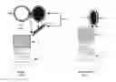
FIG. 1 illustrates one depiction of a lid for a container forming a first embodiment of the present invention;
FIG. 1A illustrates a second depiction of a lid for a container;
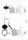
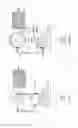
FIG. 2 illustrates a perforated seal on top of a container provided by the manufacture located under the manufactures provided cap;
FIG. 2A illustrates a glue down seal on top of a container that pops up and is held in place with a tab, provided my the manufacture located under the manufactures provided cap;
DETAILED DESCRIPTION
With reference now to the accompanying drawings, and more specifically to FIGS. 1-2, various applications of spill proof lids, caps and closures FIGS. 1 and 2 are best illustrated in FIG. 1 the cap 3 with lid 1 and snap seal 2, the lid 1 moves down on hinge 4 and snaps to cap 3. The cap 3 is than screwed on to container 5 then inserted in to position to pour and container 5 is squeezed to release lid 2 and allow liquid to pour in to receptacle. FIG. 1A is another application of a cap 9 with a hole 10 that is closed with a stopper 6. The stopper 6 is connected to retainer 8 via string 7 to keep the stopper 6 from falling out of cap 9. The retainer 8 is inserted in to container 11 and then cap 9 is screwed on to container 11 and the stopper 6 is inserted in to hole 10 then the container 11 in inserted in to position to pour and container 11 is squeezed to pop out stopper 6 and allow liquid to pour in to receptacle.
With reference now to FIG. 2 a different implementation of the closure when the cap 12 is removed has a seal 13 that has a paper or plastic seal glued on top of container 14 that has a perforation 15 that will break open when the container 14 is squeezed and allow the liquid to flow out. In reference to FIG. 2A when the cap 18 is removed the seal 19 is glued 20 down to the container 17 with a glue 20 that will release under pressure when container 17 is squeezed and retained connected to container 17 via tab 16. This will allow the liquid to flow in to the receptacle.
Claims
1. A cap with a hole in the top and a lid hinged to the cap so that when the lid is closed on the cap it latches in place and will release when a pressure is applied by squeezing the container the cap is on.
2. A cap with a hole in the top similar to claim 1 with a stopper instead of a lid and a string passing through the hole and attached to a retainer that will pass through the opening of the container but not the hole in the cap so that when the stopper is placed in the hole it will pop out when pressure is applied by squeezing the container the cap is on.
3. A manufacture provided seal on top of the container that has perforations in the seal that will allow it to bust open under pressure when the container is squeezed, this action would be prohibited from occurring when the manufacture provided cap is in place.
4. A manufacture provided seal on top of the container that has a glue that will release under pressure when the container is squeezed and is held to the container with a strip down the side of the neck, this action would be prohibited from occurring when the manufacture provided cap is in place.
Images & Drawings included:

Sources:
- United States Patent and Trademark Office - verify current appl. status at the USPTO↗
Recent applications in this class:
- » 20050268433 2005-12-08
Virtual hinge