Guidance assembly for circular saws
US20160075049A1
2016-03-17
14/121,301
2014-09-15
✅ Patent granted
US 9,718,207 B2
2017-08-01
-
-
Stephen Choi | Evan MacFarlane
Frederick Kaufman Inc.
2035-07-25
Abstract:
A guidance assembly for circular saws comprises a monobloc structural unit that incorporates a first, discontinuous annular subassembly and a second, flat inverted at 90 degrees U-shape elongated frame subassembly. A pair of angle beams is spacedly adjustable that is positionally adaptable to support various bases of circular saws. The guidance assembly further includes a fence subassembly, placed beneath the monobloc structural unit, with which is interconnected and cooperates. To prepare the cutting operation, the blade angle of a circular saw is matched to the required angle by rotating first and second subassemblies relatively to fence subassembly. For cutting, a wooden board is placed under first and second subassemblies, so that, laterally, is positioned against a first and a second hollow bars of fence subassembly.
Applicant:
Interested in similar patents?
Get notified when new applications in this technology area are published.
Classification:
B23Q9/005 » CPC further
Arrangements for supporting or guiding portable metal-working machines or apparatus; Portable machines provided with or cooperating with guide means supported directly by the workpiece during action the guide means being fixed only on the workpiece angularly adjustable
B27B9/04 » CPC main
Portable power-driven circular saws for manual operation Guiding equipment, e.g. for cutting panels
B23Q9/00 IPC
Arrangements for supporting or guiding portable metal-working machines or apparatus
B27B11/02 » CPC further
Cross-cut reciprocating saws with power drive; Appurtenances therefor Arrangements for guiding the saw blade
Description
I. BACKGROUND OF THE INVENTION
1. Field of the Invention
The invention relates, in general, to devices for guiding power tools with respect to workpieces, and, more specifically, to a guidance assembly for circular saws.
2. Description of the Prior Art
In construction and woodworking fields use is made of portable hand-held power tool, such as circular saws, jigsaws, routers, etc., and/or larger “fixed-bed” power tools. While the hand-held power tools are common due to their portability and low cost, the fixed-bed tools that are more expensive and cumbersome are more preferred due to the precise position of a workpiece with respect to the power tool blade, resulting in a precise cut. However, fixed-bed units require fixed locations and larger working spaces.
Attempts have been made to eliminate or at least to alleviate this the above situation. Thus, for example, U.S. Pat. No. 8,047,113, granted on Nov. 1, 2011 to Nilsen for a “GUIDE FOR HAND-HELD POWER TOOL” discloses a cross-cut apparatus. The latter comprises a guide system including a housing, a guide element mounted on the housing and a linear guide rail mounted on the housing. The apparatus further includes a workpiece coupler defining a desired processing angle and an attachment system, coupled to the housing, for fixing the tool to the guide system. The main disadvantages of this guide reside in the fact that the use is limited to right angle cuts and in the fact that the guide must be mechanically attached to the power tool.
Another example is U.S. Pat. No. 8,573,101, granted on Nov. 5, 2013 to Thomaschewski for a “METHOD AND DEVICE FOR GUIDING A SAW BLADE” describes a device including: a base body having a guide slot, the base body having a first guide surface; and an angle stop comprising a second guide surface. The main shortcomings of the device reside in the fact it requires an additional stabilization, since both hands are on the tool; and that due to the guide arrangement provides a limited versatility.
II. SUMMARY OF THE INVENTION
Based on the state of the art, there is a need for an improved guidance assembly for circular saws that surmounts the existing disadvantages.
Thus, ii is an objective of the present invention to devise a guidance assembly that is precise and reliable.
It is another objective of the present invention to devise a guidance assembly that is portable and easy to use.
Generally stating, the present invention refers to guidance assembly for circular saws, which comprises a monobloc structural unit, which incorporates a first and a second subassembly and is interconnected and cooperates with a fence subassembly,
First subassembly comprises a discontinuous annular flat member having a center of symmetry, a first upside face, a second bottom face and terminating laterally and backwards in an upper end and a lower end.
Second subassembly comprises a flat, inverted at 90 degrees U-shape elongated frame, extends frontwards, towards the discontinuous annular flat member, is defined by a horizontal, longitudinal axis of symmetry and includes an upper arm ending in a top end and a lower arm ending in a bottom end. The upper end interpenetrates with the top end and the lower end interpenetrates with the bottom end, thus forming the monobloc structural unit.
Other the fact, that the upper arm, via the top end, basically interconnects with the upper end along their respective widths, a narrow strip, detached from the upper arm, extends beneath it, horizontally and forwards into an interior of the discontinuous annular flat member.
The center of symmetry of the discontinuous annular flat member is so displaced vertically and downwards with respect to the horizontal, longitudinal axis of symmetry, that a positional eccentricity is created.
The lower arm, via the bottom end, after combining with the lower end, continues laterally, forwards until it intersects a curvilinear, concave, interior surface of the discontinuous annular flat member.
An upper circular through slot and a lower circular through slot, both located in and being concentric with the discontinuous annular flat member, traverse zones of the latter, respectively a top zone and a bottom zone.
An upwardly directed arrow mark engraved immediately above the upper circular through slot and centered on the vertical diameter that passes through the center of symmetry of the discontinuous annular flat member. Angle-indicating, equidistantly engraved marks incrementally extend at the left and right of the upwardly directed arrow mark, being preceded by an engraved inscription “HIP OR VALLEY”. The upwardly directed arrow mark, the angle-indicating, equidistantly engraved marks and the previously mentioned inscription being all disposed on an arc of a circle.
A zero mark, engraved as “0”, coincides vertically with the upwardly directed arrow mark and is flanked, at left and right up to 90°, by a series of engraved, angle-indicating marks. The series of engraved, angle-indicating marks, at the left, is preceded by an engraved inscription “ROOF PITCH”. The zero mark, engraved as “0” and the series of equidistantly engraved, angle-indicating marks are all disposed on an arc of a circle adjacent to external periphery of the discontinuous annular flat member.
The engraved mark 90 coinciding with the vertical diameter of the discontinuous annular flat member, is disposed above and in contact with the lower circular through slot, in proximity of internal periphery of the discontinuous annular flat member. The first series of decremental marks, equidistantly engraved, adjacent to an external periphery of the discontinuous annular flat member, extends upwardly from a 90 engraved mark, being collinear with the engraved mark 90, up to a “0” (zero) mark, while a second series of decremental marks; equidistantly engraved, adjacent to the external periphery of the discontinuous annular flat member, extends downwards from the 90 engraved mark, above mentioned, up to a mark 60.
A bracket, perpendicular to the longitudinal axis of symmetry of the flat, inverted at 90 degrees U-shape elongated frame, is placed in an interior of the discontinuous annular flat member, close, at the left, to the internal periphery of the latter, and is delimited vertically, at its upper part, by the narrow strip and at its lower part by the interior of the discontinuous annular flat member.
A web, which is a mirror image of the bracket, is situated at the farthest right extremity of the inverted at 90 degrees U-shape elongated frame;
The bracket and the web incorporate, at their ends, a pair of elongated through-passage openings provided with chamfered edges. The bracket and the web have their underside retracted from the second bottom face;
A rigidity wall, retracted from the first upside face, encompasses the flat, inverted at 90 degrees U-shape elongated frame which is located in the interior of the discontinuous annular flat member. A pair of stiffening ribs joining the interior of the discontinuous annular flat member with the flat, inverted at 90 degrees U-shape elongated frame, respectively via the bracket and the narrow strip, coincide directionally, one of the pair of stiffening ribs-with vertical diameter and the other one of the pair of stiffening ribs with horizontal diameter of the discontinuous annular flat member. The pair of stiffening ribs protrudes from the rigidity wall and extend upwards up to the first upside face;
A pair of angle beams, each one of the pair of angle beams being provided with unequal legs, one vertical leg and the other-horizontal leg. The vertical leg is provided with flat ends at both extremities. The vertical leg of one of the pair of angle beams is so positioned as to face another vertical leg of the other of the pair of angle beams. Each flat end is provided with a threaded opening. Screws with countersunk heads are inserted via the pair of elongated and spaced through-passage openings, located at the extremities of the bracket and of the web and provided with chamfered edges and, then, tightened into the threaded openings, distances between the vertical legs being adjustable so that the pair of angle beams is adaptable to receive various circular saws with various bases. A thickness of the pair of angle beams is so chosen that the latter does not protrude beyond the second bottom face;
The second bottom face of the monobloc structural unit is formed by a flat surface interrupted by a rectangular opening delimited by internal edges of the bracket and the web, by internal edges of the upper arm and of the narrow strip, detached from the upper arm, and by internal edge of the lower arm which via the bottom end, after interconnecting the lower end, continues laterally and forwards until it intersects a curvilinear, concave, interior surface of the discontinuous annular flat member. The flat surface is interrupted by a ring type channel having a U-shape cross section. The ring type channel extends outside, at a relative short distance from of the upper circular through slot and the lower circular through slot. An internal edge of the ring type channel is coplanar with the second bottom face, while an external edge of the ring type channel is somewhat retracted with respect to the internal edge. The external edge extends outwardly into an external ring with which is coplanar;
The external ring extends backwardly, at both external margins of the upper arm and the lower arm, by elongated strips, both coplanar with the external ring;
The fence subassembly, which is interconnected and cooperates with the first and second subassemblies that constitute a monobloc structural unit, comprises an annular flat segment provided on its top side with planar circular zones projecting beyond the annular flat segment and shaped and sized for engaging the ring type channel and, respectively, the external ring. A first hollow bar, having a rectangular cross-section and extending from both sides of a right extremity of annular flat segment, is so attached to the annular flat segment that their upper surfaces are coplanar. An internal end of the first hollow bar, at the right, is so cut off that an obtuse angle is formed. A second hollow bar, having, as well, the previously mentioned rectangular cross-section and extending from both sides of a left extremity of the annular segment is so attached to the annular flat segment that their upper surfaces are coplanar. An internal end of the second hollow bar being so cut off, at the left, that an acute angle is formed. A pair of screws securely attached vertically to the annular flat segment is so spaced as to penetrate through the upper circular through slot and the lower circular through slot: A pair of threaded coupling pieces together with the pair of screws are used to positionally secure the fence subassembly to the first and second subassemblies. First hollow bar is provided outside the annular flat segment, at the left, with a plurality of indicating marks extending from “9” to “20”.
II. BRIEF DESCRIPTION OF THE DRAWINGS
The invention is illustrated by the accompanying drawings in which:
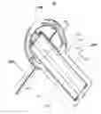
FIG. 1 is a perspective view of the guidance assembly;
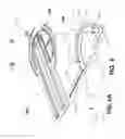
FIG. 2 is a top view of the first and second subassemblies which form a monobloc structural unit;
FIG. 2A is an enlarged partial view of a zone A of FIG. 2;
FIG. 2B is an enlarged partial view of a zone B of FIG. 2;
FIG. 3 is an exploded view of the monobloc structural unit depicted in FIG. 2;
FIG. 4 is a back view of the monoblock structural unit shown in FIGS. 2 and 3;
FIG. 5 is a cross-section of FIG. 4, along line C-C;
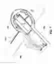
FIG. 6 is an exploded view of the guidance assembly;
FIG. 6 A illustrates internal ends of the first and second hollow bars of the fence subassembly; and
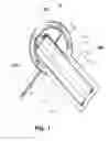
FIG. 7 is a perspective view of the guidance assembly, ready for use.
III. DESCRIPTION OF THE PREFERRED EMBODIMENT
The accompanying drawings, as above described, illustrate a preferred embodiment of a guidance assembly for circular saws.
This preferred assembly is generally designated with numeral 10. For convenience, in the following disclosure the guidance assembly for circular saws will be named “guidance assembly 10”.
As a caveat, before an embodiment of the present invention is explained in detail, it is to be understood that the invention is not limited in its application to the structural details and the arrangements of the components set forth in the following description and illustrated in the accompanying drawings. The invention is applicable to other embodiments and of being practiced or of being carried out in various variants. Also, it to be understood that the terms used herein with reference to the orientation of the “guidance assembly 10” (such as, for example, terms like “front”, “back”, “upper”, “lower”, “horizontal”, “vertical”, “forward”, “backward” and the like), are only used to better understand the description of the present invention with reference to its usual, horizontal position of use.
Guidance assembly 10 comprises, a monobloc structural unit, which, in order to facilitate the description and understanding of its structure, is conveniently divided in the following two subassemblies that in, reality, compound in one integral, unitary body:
-
- a first, discontinuous annular flat, subassembly 100, further named “first subassembly 100”, defined by a center of symmetry (not shown), having a first face 102 delimiting its upside and a second face 104 delimiting its bottom and terminating laterally and backwards in an upper end 106 and in a lower end 108;
- a second, flat inverted at 90 degrees U-shape elongated frame subassembly 200, further named “second subassembly 200”, extending frontwards, towards first subassembly 100 and, defined by a horizontal, longitudinal axis of symmetry 202, includes an upper arm 204 ending in a top end 206 and a lower arm 208 ending in a bottom end 210; upper end 106 interpenetrating with top end 206 and lower end 108 interpenetrating with bottom end 210, thus forming the monobloc structural unit, mentioned above;
other the fact, that upper arm 204, respectively its top end 206, basically interconnects with upper end 106 along their widths, a narrow strip 212, detached from upper arm 204, extends beneath it, horizontally and forwards into the interior of first subassembly 100;
the center of symmetry of first subassembly 100, being displaced vertically and downwards with respect to horizontal, longitudinal axis of symmetry 202, a positional eccentricity is created; lower arm 208, via its bottom end 210, after combining with lower end 108, continues laterally, forwards until it intersects a curvilinear, concave, interior surface 110 of first subassembly 100; an upper circular through slot 112 and a lower circular through slot 114, both located in and concentric with first subassembly 100 traverse zones of the latter, respectively a top zone 116 and a bottom zone 118;
an upwardly directed arrow mark 120 is engraved, immediately above upper circular through slot 112 and is centered on the vertical diameter that passes through the center of symmetry of first subassembly 100; angle-indicating, equidistantly engraved marks 122 incrementally extend at the left and right of upwardly directed arrow mark 120, are preceded by an engraved inscription “HIP OR VALLEY”; upwardly directed arrow mark 120, angle-indicating, equidistantly engraved marks 122 and the previously mentioned inscription are all disposed on an arc of a circle;
a zero mark, engraved as “0”, coincides linearly with upwardly directed arrow mark 120 and is flanked, at left and right up to 90°, by series of engraved, angle-indicating marks 124; the series of engraved, angle-indicating marks 124, at the left, is preceded by an engraved inscription “ROOF PITCH”; the zero mark, engraved as “0” and the series of equidistantly engraved, angle-indicating marks 124 are all disposed on an arc of a circle adjacent to external periphery 126 of first assembly 100;
an engraved mark “90” coinciding with vertical diameter of first assembly 100 is disposed above and in contact with lower circular through slot 114, in proximity of internal periphery of first subassembly 100; a first series of decremental marks 128 equidistantly engraved, adjacent to external periphery 126 of first subassembly 100, extends upwardly from a “90” engraved mark, collinear with previously mentioned engraved mark “90”, up to a “0” (zero) mark, while a second series of decremental marks 130, equidistantly engraved, adjacent to external periphery 126 of first subassembly 100, extends downwards from “90” engraved mark, above mentioned, up to a mark “60”;
a bracket 132, perpendicular to longitudinal axis of symmetry 202 of second subassembly 200, is located in the interior of first subassembly 100, close, at the left, to the internal periphery of the latter, and is delimited vertically, at its upper part, by narrow strip 212 and at its lower part by the interior of first subassembly 100;
a farthest right extremity of second subassembly 200 incorporates a zone 214, oppositely located and functionally equivalent to bracket 132; bracket 132 and zone 214 include, at their ends, a pair of elongated through-passage openings PO provided with chamfered edges; bracket 132 and zone 214 have their underside retracted from second face 104;
a rigidity wall 134, retracted from first face 102, encompasses that portion of second subassembly 202 which is located in the interior of first subassembly 100; a pair of stiffening ribs 136 joining the interior of first subassembly 100 with second subassembly 200, respectively via bracket 132 and narrow strip 212, coincide directionally, one of the pair with vertical diameter and the other one with horizontal diameter of first subassembly 100; the pair of stiffening ribs 136 protrudes from rigidity wall 134 and extends upwards up to first face 102;
a pair of angle beams 216, wherein each one of the pair of angle beams 216 is provided with unequal legs, one vertical leg 218 and one horizontal leg 220, vertical leg 218 being interrupted at both extremities; vertical leg 218 of one of the pair of angle beams 216 is so positioned as to face an opposite vertical leg 218 of the other of the pair of angle beam 216; both ends of each horizontal leg 220 is provided with threaded opening 222; screws with countersunk heads 224 are inserted via the pair of elongated and spaced through-passage openings PO at the extremities of bracket 132 and of zone 214 and then tightened into threaded openings 222; distances between opposite vertical legs 218 are adjustable so the pair of angle beams 216 is adaptable to receive various bases of circular saws; a thickness of the pair of angle beams 216 is so chosen that the latter does not protrude beyond second face 204;
second face 104 consists essentially of a flat surface having a rectangular opening delimited by interior edges of bracket 132 and zone 214, by internal edges of upper arm 204 and of narrow strip 212 and by the internal edge of lower arm 208 which via its bottom end 210, after interconnecting lower end 108, continues laterally, forwards until it intersects curvilinear, concave, interior surface of first subassembly 100; flat surface includes a ring type channel 226 having a U-shape cross section; ring type channel 226 extends outside, at a relative short distance of upper circular through slot 112 and lower circular through slot 114; an internal edge 228 of ring type channel 226 is coplanar with second face 104, while an external edge 230 of ring type channel 226 is somewhat retracted with respect to internal edge 228; external edge 230 extends outwardly into an external ring 232 with which is coplanar;
external ring 232 extends backwardly, at both external margins of upper arm 204 and lower arm 208, by elongated strips 234, both coplanar with external ring 230;
guidance assembly 10 further comprises: - a fence subassembly 300, which is interconnected and cooperates with first and second subassemblies 100 and 200 that constitute a monobloc structural unit, comprises an annular flat segment 305 provided on its top side with planar circular zones 310 and 315 projecting beyond annular flat segment 305 and shaped and sized for engaging ring type channel 224 and, respectively, external ring 230; a first hollow bar 320, having a rectangular cross-section and extending from both sides of a right extremity of annular flat segment 305, is so attached to annular flat segment 305 that their upper surfaces are coplanar; an internal end 325 of first hollow bar 320 is backwardly cut off that an obtuse angle is formed; a second hollow bar 330, having, as well, the previously mentioned rectangular cross-section and extending from both sides of a left extremity of annular segment 305 is so attached to annular flat segment 305 that their upper surfaces are coplanar, an internal end 335 of second hollow bar 330 is forwards cut off that an acute angle is formed; a pair of screws 340 securely attached vertically to annular flat segment 305 is so spaced as to penetrate through upper circular through slot 112 and lower circular through slot 114; a pair of threaded coupling pieces 345 together with the pair of screws 340 are used to positionally secure fence subassembly 300 to subassemblies 100 and 200; first hollow bar 320 is provided outside annular flat segment 305, at the left, with a plurality of indicating marks 350 extending from “9” to “20”.
Use of the “Guidance Assembly for Circular Saws”
The operational steps are:
Placing a wooden board WB under first and second subassemblies 100 and 200, so that, laterally, is positioned against first and second hollow bars 320 and 330 offence subassembly 300;
Matching the blade angle of a circular saw to the angle you need to cut, by rotating subassemblies 100 and 200 relatively to fence subassembly 300;
Tightening the pair of threaded coupling pieces 345;
Adjusting the distance between the pair of angle beams 216 as to accommodate a base of a circular saw;
Securing the pair of angle beams 216; and Turning on the saw power and, then, translating the circular saw along the pair the angle beams 216.
Claims
What I claim is:1. A guidance assembly for circular saws comprising a monobloc structural unit, which incorporates a first and a second subassembly and is interconnected and cooperates with a fence subassembly,
first subassembly comprises:
a discontinuous annular flat member having a center of symmetry, a first upside face, a second bottom face and terminating laterally and backwards in an upper end and a lower end;
second subassembly comprises:
a flat, inverted at 90 degrees U-shape elongated frame, extending frontwards, towards said discontinuous annular flat member, defined by a horizontal, longitudinal axis of symmetry and including an upper arm ending in a top end and a lower arm ending in a bottom end; said upper end interpenetrating with said top end and said lower end interpenetrating with said bottom end, thus forming said monobloc structural unit;
other the fact, that said upper arm, via said top end, basically interconnects with said upper end along their respective widths, a narrow strip, detached from said upper arm, extends beneath it, horizontally and forwards into an interior of said discontinuous annular flat member;
said center of symmetry of said discontinuous annular flat member being displaced vertically and downwards with respect to said horizontal, longitudinal axis of symmetry, thus a positional eccentricity being created;
said lower arm, via said bottom end, after combining with said lower end, continues laterally, forwards until it intersects a curvilinear, concave, interior surface of said discontinuous annular flat member;
an upper circular through slot and a lower circular through slot, both located in and being concentric with said discontinuous annular flat member traverse zones of the latter, respectively a top zone and a bottom zone;
an upwardly directed arrow mark engraved immediately above said upper circular through slot and centered on the vertical diameter that passes through said center of symmetry of said discontinuous annular flat member, angle-indicating, equidistantly engraved marks incrementally extending at the left and right of said upwardly directed arrow mark, being preceded by an engraved inscription “HIP OR VALLEY”; said upwardly directed arrow mark, said angle-indicating, equidistantly engraved marks and the previously mentioned inscription being all disposed on an arc of a circle;
a zero mark, engraved as “0”, coinciding vertically with said upwardly directed arrow mark and being flanked, at left and right up to 90°, by series of engraved, angle-indicating marks; said series of engraved, angle-indicating marks, at the left, being preceded by an engraved inscription “ROOF PITCH”; said zero mark, engraved as “0” and said series of equidistantly engraved, angle-indicating marks being all disposed on an arc of a circle adjacent to external periphery of said discontinuous annular flat member;
an engraved mark 90 coinciding with the vertical diameter of discontinuous annular flat member, being disposed above and in contact with said lower circular through slot, in proximity of internal periphery of said discontinuous annular flat member; a first series of decremental marks, equidistantly engraved, adjacent to an external periphery of said discontinuous annular flat member, extending upwardly from a 90 engraved mark, collinear with said engraved mark 90, up to a “0” (zero) mark, while a second series of decremental marks, equidistantly engraved, adjacent to said external periphery of said discontinuous annular flat member, extending downwards from said 90 engraved mark, above mentioned, up to a mark 60;
a bracket, perpendicular to said longitudinal axis of symmetry of said flat, inverted at 90 degrees U-shape elongated frame, being placed in an interior of said discontinuous annular flat member, close, at the left, to the internal periphery of the latter, and being delimited vertically, at its upper part, by said narrow strip and at its lower part by said interior of said discontinuous annular flat member;
a web, which is a mirror image of said bracket, is situated at the farthest right extremity of said inverted at 90 degrees U-shape elongated frame;
said bracket and said web incorporating, at their ends, a pair of elongated through-passage openings being provided with chamfered edges; said bracket and said web having their underside retracted from said second bottom face;
a rigidity wall, retracted from said first upside face, encompassing said flat, inverted at 90 degrees U-shape elongated frame which is located in said interior of said discontinuous annular flat member; a pair of stiffening ribs joining said interior of said discontinuous annular flat member with said flat, inverted at 90 degrees U-shape elongated frame, respectively via said bracket and said narrow strip, coinciding directionally, one of said pair of stiffening ribs-with vertical diameter and the other one of said pair of stiffening ribs with horizontal diameter of said discontinuous annular flat member; said pair of stiffening ribs protruding from said rigidity wall and extending upwards up to said first upside face; a pair of angle beams, each one of said pair of angle beams being provided with unequal legs, one vertical leg and the other-horizontal leg, said vertical leg being provided with flat ends at both extremities; said vertical leg of one of said pair of angle beams being so positioned as to face another said vertical leg of the other of said pair of angle beams; each said flat end being provided with a threaded opening; screws with countersunk heads being inserted via said pair of elongated and spaced through-passage openings, located at the extremities of said bracket and of said web and provided with chamfered edges and, then, tightened into said threaded openings, distances between said vertical legs being adjustable so that said pair of angle beams is adaptable to receive various circular saws with various bases; a thickness of said pair of angle beams is so chosen that the latter does not protrude beyond said second bottom face;
said second bottom face of said monoblock structural unit being formed by a flat surface interrupted by a rectangular opening delimited by internal edges of said bracket and said web, by internal edges of said upper arm and of said narrow strip, detached from said upper arm, and by internal edge of said lower arm which via said bottom end, after interconnecting said lower end, continues laterally and forwards until intersects a curvilinear, concave, interior surface of said discontinuous annular flat member; said flat surface being also interrupted by a ring type channel having a U-shape cross section; said ring type channel extending outside, at a relative short distance from of said upper circular through slot and said lower circular through slot; a internal edge of said ring type channel being coplanar with said second bottom face, while an external edge of said ring type channel is somewhat retracted with respect to said internal edge; said external edge extending outwardly into an external ring with which is coplanar;
said external ring extending backwardly, at both external margins of said upper arm and said lower arm, by elongated strips, both coplanar with said external ring;
said fence subassembly, which is interconnected and cooperates with said first and second subassemblies that constitute a monobloc structural unit, comprising an annular flat segment provided on its top side with planar circular zones projecting beyond said annular flat segment and shaped and sized for engaging said ring type channel and, respectively, said external ring; a first hollow bar, having a rectangular cross-section and extending from both sides of a right extremity of annular flat segment, is so attached to said annular flat segment that their upper surfaces are coplanar, an internal end of said first hollow bar being so cut off that an obtuse angle is formed; a second hollow bar, having, as well, said previously mentioned rectangular cross-section and extending from both sides of a left extremity of said annular segment being so attached to said annular flat segment that their upper surfaces are coplanar; an internal end of said second hollow bar being so cut off that an acute angle is formed; a pair of screws securely attached vertically to said annular flat segment being so spaced as to penetrate through said upper circular through slot and said lower circular through slot; a pair of threaded coupling pieces together with said pair of screws being used to positionally secure said fence subassembly to said first and second subassemblies; first hollow bar being provided outside said annular flat segment, at the left, with a plurality of indicating marks extending from “9” to “20”.
Images & Drawings included:


Sources:
- United States Patent and Trademark Office - verify current appl. status at the USPTO↗
Recent applications in this class:
- » 20240391128 2024-11-28
Circular Saw Guiding Device, Method of Customization, and Method Of Use - » 20240262000 2024-08-08
Circular saw guide device - » 20240123648 2024-04-18
PANEL SAW ASSEMBLY - » 20230382002 2023-11-30
POWER TOOL GUIDE AND POWER TOOL GUIDE ASSEMBLY - » 20230382001 2023-11-30
POWER TOOL GUIDE AND POWER TOOL GUIDE ASSEMBLY - » 20230382000 2023-11-30
POWER TOOL GUIDE AND POWER TOOL GUIDE ASSEMBLY - » 20230381999 2023-11-30
POWER TOOL GUIDE AND POWER TOOL GUIDE ASSEMBLY - » 20220242003 2022-08-04
ALIGNMENT JIG FOR SAW - » 20210362365 2021-11-25
Portable machining apparatus with mount to receive and retain an auxiliary fitting - » 20210178627 2021-06-17
POWER TOOL GUIDE WITH POSITIVE ALIGNMENT