Optical lens
US20160116714A1
2016-04-28
14/882,850
2015-10-14
✅ Patent granted
US 9,804,363 B2
2017-10-31
-
-
William Choi
WPAT, PC
2035-10-14
Abstract:
An optical lens includes a first lens, a second lens, a third lens, a fourth lens and a fifth lens arranged sequentially along an optical axis from an magnified side to a minified side. A center thickness of the first lens is TH1, a center thickness of the second lens is TH2, a center thickness of the third lens is TH3, a center thickness of the fourth lens is TH4, a center thickness of the fifth lens is TH5, and an effective focal length of the optical lens is EFL, wherein the optical lens fits at least one of the following conditions: (1) 0.52<(TH1+TH2+TH3)/EFL<1.0; (2) 0.5<(TH3+TH4+TH5)/EFL<0.65; and (3) (TH1+TH2+TH3)/(TH3+TH4+TH5)>1.20. The optical lens can reduce aberration and has high resolution.
Assignee:
- YOUNG OPTICS INC. 259 🇹🇼 Hsinchu, Taiwan
Applicant:
Interested in similar patents?
Get notified when new applications in this technology area are published.
Classification:
G02B27/0025 » CPC further
Optical systems or apparatus not provided for by any of the groups - for optical correction, e.g. distorsion, aberration
G02B27/00 IPC
Optical systems or apparatus not provided for by any of the groups -
G02B13/0045 » CPC main
Optical objectives specially designed for the purposes specified below; Miniaturised objectives for electronic devices, e.g. portable telephones, webcams, PDAs, small digital cameras characterised by the lens design having at least one aspherical surface having five or more lenses
G02B13/18 IPC
Optical objectives specially designed for the purposes specified below with lenses having one or more non-spherical faces, e.g. for reducing geometrical aberration
G02B3/02 IPC
Simple or compound lenses with non-spherical faces
G02B9/60 » CPC further
Optical objectives characterised both by the number of the components and their arrangements according to their sign, i.e. + or - having five components only
G02B13/00 IPC
Optical objectives specially designed for the purposes specified below
Description
FIELD OF THE INVENTION
The present invention relates to an optical element, and more particularly to an optical lens.
BACKGROUND OF THE INVENTION
With recent advances in technology, mobile phones, digital cameras and other portable electronic devices continue to flourish. In order to satisfy the thinning tendency of the mobile phones and the digital cameras, the demands for compact image sensor modules are increased. Meanwhile, with technological advances and size reductions of image sensing elements, such as charge coupled device (CCD) or complementary metal-oxide semiconductor image sensor (CMOS image sensor), to correspondingly reduce the length of the optical lens installed inside of the image sensor module is needed.
To avoid from shooting with poor quality, while reducing the length of the optical lens, the optical lens should still have great optical performance. Therefore, the amount of lens of the conventional optical lens increases gradually from 2-3 for reducing aberration and reaching the resolution which fits the imaging sensing element. However, to excessively increase the amount of the lens will cause the length of the optical lens to be too long. Therefore, how to reach balance between the length and optical performance of the optical lens is a problem in optical lens design.
SUMMARY OF THE INVENTION
The present invention is directed to an optical lens having a short length and good optical performance.
One embodiment of the present invention provides an optical lens which includes a first lens, a second lens, a third lens, a fourth lens and a fifth lens arranged sequentially along an optical axis from an magnified side to a minified side. A center thickness of the first lens is TH1, a center thickness of the second lens is TH2, a center thickness of the third lens is TH3, a center thickness of the fourth lens is TH4, a center thickness of the fifth lens is TH5, and an effective focal length of the optical lens is EFL, wherein the optical lens fits at least one of the following conditions: (1) 0.52<(TH1+TH2+TH3)/EFL<1.0; (2) 0.5<(TH3+TH4+TH5)/EFL<0.65; and (3)(TH1+TH2+TH3)/(TH3+TH4+TH5)>1.20.
The optical lens of one embodiment of the present invention can reduce aberration and has high resolution via the first, second, third, fourth and fifth lenses which have the positive, negative, positive, negative and negative refractive power, respectively. Moreover, the optical lens fits at least one of the following conditions: 0.52<(TH1+TH2+TH3)/EFL<1.0; 0.5<(TH3+TH4+TH5)/EFL<0.65; and (TH1+TH2+TH3)/(TH3+TH4+TH5)>1.20, and therefore the optical lens can have a short total length, and be easily manufactured.
BRIEF DESCRIPTION OF THE DRAWINGS
The present invention will become more readily apparent to those ordinarily skilled in the art after reviewing the following detailed description and accompanying drawings, in which:
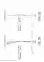
FIG. 1 is a schematic structural view of an optical lens in accordance with an embodiment of the present invention;
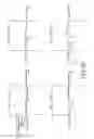
FIG. 2A is a field curvature diagram of an optical lens in accordance with an embodiment of the present invention;
FIG. 2B is a distortion diagram of an optical lens in accordance with an embodiment of the present invention;
FIG. 2C is a transverse ray fan plot of four different fields of view of an optical lens in accordance with an embodiment of the present invention;
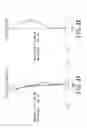
FIG. 3 is a schematic structural view of an optical lens in accordance with another embodiment of the present invention;
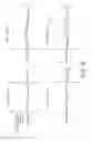
FIG. 4A is a field curvature diagram of an optical lens in accordance with another embodiment of the present invention;
FIG. 4B is a distortion diagram of an optical lens in accordance with another embodiment of the present invention; and
FIG. 4C is a transverse ray fan plot of four different fields of view of an optical lens in accordance with another embodiment of the present invention.
DETAILED DESCRIPTION OF PREFERRED EMBODIMENTS
The present invention will now be described more specifically with reference to the following embodiments. It is to be noted that the following descriptions of preferred embodiments of this invention are presented herein for purpose of illustration and description only. It is not intended to be exhaustive or to be limited to the precise form disclosed.
Please refer to FIG. 1, which is a schematic structural view of an optical lens in accordance with an embodiment of the present invention. As shown in FIG. 1, the optical lens 100 in the present embodiment includes a first lens L1, a second lens L2, a third lens L3, a fourth lens L4 and a fifth lens L5 arranged sequentially along an optical axis 110 from a magnified side to a minified side. A center thickness of the first lens L1 (along the optical axis 110) is TH1, a center thickness of the second lens is TH2, a center thickness of the third lens is TH3, a center thickness of the fourth lens is TH4, a center thickness of the fifth lens is TH5, an effective focal length of the optical lens 100 is EFL, and the optical lens fits at least one of the following conditions: (1) 0.52<(TH1+TH2+TH3)/EFL<1.0; (2) 0.5<(TH3+TH4+TH5)/EFL<0.65; and (3) (TH1+TH2+TH3)/(TH3+TH4+TH5)>1.20.
In this embodiment, the first lens L1, for instance, has positive refractive power, the second lens L2, for instance, has negative refractive power, the third lens L3, for instance, has positive refractive power, the fourth lens L4, for instance, has negative refractive power, and the fifth lens L5, for instance, has negative refractive power. The first lens L1, for instance, is a biconvex lens for providing refractive power to the optical lens 100. The first lens L1 includes a first surface S1 and a second surface S2, and at least one of the first surface S1 and the second surface S2 is, for instance, an aspheric surface for correction of spherical aberration. The second lens L2 includes a third surface S3 and a forth surface S4, wherein the third surface S3 is, for instance, a concave surface. In another embodiment, the third surface S3 can be designed as a convex surface. Moreover, the forth surface S4 is, for instance, a concave surface for balance of chromatic aberration, such as axial color and lateral color.
The third lens L3 includes a fifth surface S5 and a sixth surface S6, wherein the fifth surface S5 is, for instance, a concave surface, and the sixth surface S6 is, for instance, a convex surface. The third lens L3 can provide refractive power to the optical lens 100 and correct astigmatism. The fourth lens L4 includes a seventh surface S7 and a eighth surface S8. A center area of the seventh surface S7 near the optical axis 110 is a convex surface, and a center area of the eighth surface S8 near the optical axis 110 is a concave surface for correction of off-axis aberration, such as coma and astigmatism. The fifth lens L5 includes a ninth surface S9 and a tenth surface S10, wherein a peripheral area of the ninth surface S9 away from the optical axis 110 includes an inflection point P, a center area of the ninth surface S9 near the optical axis 110 is a convex surface, and a center area of the tenth surface S10 near the optical axis 110 is a concave surface for correction of off-axis aberration, such as coma and astigmatism.
The first lens L1, the second lens L2 and the third lens L3 of this embodiment are, for instance, made of plastic, however, in another embodiment, the first lens L1, the second lens L2 and the third lens L3 can be made of glass. The first lens L1, the second lens L2 and the third lens L3 which are manufactured by glass molding respectively have a higher refractive index, so that the optical lens 100 has better imaging performance. Moreover, the fourth lens L4 and the fifth lens L5 can be made of plastic or glass. The fourth lens L4 and the fifth lens L5 respectively have a refractive index in the range of, for instance, 1.5 to 1.7, however, the present invention is not limited thereto.
The optical lens 100 of this embodiment can further include an aperture stop 120 set on the first surface S1 of the first lens L1 (shown in the dotted lines). In addition, the optical lens 100 can further include a filter 130 set between the fifth lens L5 and an imaging surface 140. The filter 130 is, for instance, an infrared cut (IR cut) filter to avoid affecting the imaging color by infrared light. However, the present invention is not limited to the type of the filter 130. Depending on usage requirements, the filter 130 can also be omitted.
The followings will describe the preferred embodiment of the optical lens 100, it is to be understood that the invention needs not be limited to the disclosed embodiment. On the contrary, it is intended to cover various modifications and similar arrangements included within the spirit and scope of the appended claims which are to be accorded with the broadest interpretation so as to encompass all such modifications and similar structures.
| TABLE 1 | ||||
| Radius of | Refractive | Abbe | ||
| Surface | curvature (mm) | Interval (mm) | index | number |
| ST | infinity | −0.066 | 1.335 | 0 |
| S1 | 2.288 | 0.715 | 1.544 | 55.914 |
| S2 | −2.519 | 0.038 | ||
| S3 | −9.868 | 0.220 | 1.637 | 23.231 |
| S4 | 4.510 | 0.399 | ||
| S5 | −2.496 | 0.626 | 1.544 | 55.914 |
| S6 | −0.989 | 0.149 | ||
| S7 | 3.813 | 0.299 | 1.531 | 56.043 |
| S8 | 1.139 | 0.259 | ||
| S9 | 1.170 | 0.300 | 1.637 | 23.231 |
| S10 | 0.958 | 0.758 | ||
| S11 | infinity | 0.210 | equal to the | 3.133 |
| refractive | ||||
| index of | ||||
| BK7 glass | ||||
As shown in Table 1, the surface ST is the surface of the aperture stop 120, and the surface S11 is the surface of the filter 130. A value of the interval of each surface as shown in Table 1 is a straight line distance between this surface and the adjacent surface on right side along the optical axis 110. For example, the value of the interval of the first surface S1 of the first lens L1 is the straight line distance between the first surface S1 and the first imaging side surface S2 along the optical axis 110. It should be noted that the value of the interval of the surface ST is the straight line distance between the surface ST and the first surface S1 along the optical axis 110. Because the first surface S1 is on left side of the surface ST, the value of the interval of the surface ST is represented as negative.
In this embodiment, all of the first lens L1, the second lens L2, the third lens L3, the fourth lens L4 and the fifth lens L5 are, for instance, aspheric lenses, wherein the shapes of the first surface S1, the second surface S2, the third surface S3, the forth surface S4, the fifth surface S5, the sixth surface S6, the seventh surface S7, the eighth surface S8, the ninth surface S9, and the tenth surface S10 fit the following aspheric equation:
Z ( h ) = h 2 r 1 + 1 - ( 1 + k ) ( h 2 / r 2 ) + C 2 h 2 + C 4 h 4 + C 6 h 6 + C 8 h 8 + C 10 h 10 …
In this equation, “Z(h)” presents sag alone the optical axis 110, “r” is the radius of curvature adjacent to the optical axis 110 (as shown in Table 1). “k” is a conic constant. “h” is the height of aspheric, which is the distance from the center of the lens to the edge of the lens. Each of “C2”, “C4”, “C6”, “C8”, “C10”, “C12” and “C14” is an aspheric coefficient, wherein “C2” of each of the surfaces S1 to S10 is zero. The remaining values are detailed in Tables 2 and 3 below.
| TABLE 2 | |||||
| S1 | S2 | S3 | S4 | S5 | |
| k | −7.187 | −5.590 | 5.018E+01 | −1.961E+01 | −4.405E+01 |
| C4 | −1.233E−02 | −3.160E−01 | −8.851E−02 | 1.584E−01 | −3.981E−01 |
| C6 | −1.337E−01 | 2.066E−01 | 5.264E−02 | −2.974E−01 | 7.572E−01 |
| C8 | 1.575E−01 | −7.770E−01 | −1.127E+00 | 3.977E−01 | −5.082E−01 |
| C10 | −9.860E−01 | 2.153E+00 | 3.636E+00 | −1.311E+00 | −2.048E+00 |
| C12 | 1.657E+00 | −3.108E+00 | −4.909E+00 | 1.953E+00 | 4.420E+00 |
| C14 | −1.468E+00 | 1.614E+00 | 2.382E+00 | −1.310E+00 | −3.044E+00 |
| TABLE 3 | |||||
| S6 | S7 | S8 | S9 | S10 | |
| k | −9.891E−01 | −5.011E+01 | −2.642E+00 | −7.150E−01 | −3.031E+00 |
| C4 | 6.846E−02 | 8.497E−03 | −1.407E−01 | −3.665E−01 | −1.908E−01 |
| C6 | −6.199E−02 | −1.381E−01 | 5.053E−02 | 1.030E−01 | 6.884E−02 |
| C8 | −7.572E−02 | 3.794E−02 | −3.569E−02 | −1.117E−02 | −1.798E−02 |
| C10 | 2.067E−01 | 9.649E−03 | 1.683E−02 | −6.315E−04 | 5.564E−03 |
| C12 | −2.974E−01 | −5.563E−03 | −4.577E−03 | 1.128E−03 | −8.158E−04 |
| C14 | 1.511E−01 | −2.818E−03 | 6.374E−04 | −2.996E−04 | 5.427E−07 |
The optical lens 100 of the present embodiment can reduce aberration and has high resolution via the first, second, third, fourth and fifth lenses L1, L2, L3, L4 and L5 which have the positive, negative, positive, negative and negative refractive power, respectively. Moreover, since the optical lens 100 fits at least one of the following conditions: 0.52<(TH1+TH2+TH3)/EFL<1.0; 0.5<(TH3+TH4+TH5)/EFL<0.65; and (TH1+TH2+TH3)/(TH3+TH4+TH5)>1.20, the optical lens 100 of the present embodiment can have a short total length and be easily manufactured. For example, if (TH1+TH2+TH3)/EFL<0.52, the thickness of each of the first lens L1, the second lens L2 and the third lens L3 would be too thin to be easily manufactured. It will increase cost of manufacture. If (TH1+TH2+TH3)/EFL>1.0, the thickness of each of the first lens L1, the second lens L2 and the third lens L3 would be too thick so that the total length of the optical lens 100 would be too long.
FIG. 2A and FIG. 2B are a field curvature diagram and a distortion diagram of an optical lens in accordance with an embodiment of the present invention, and FIG. 2C is a transverse ray fan plot of four different fields of view of an optical lens in accordance with an embodiment of the present invention. Since curve lines as shown in FIGS. 2A to 2C are within the standard, the optical lens 100 of this embodiment can have good imaging quality.
FIG. 3 is a schematic structural view of an optical lens in accordance with another embodiment of the present invention. Referring to FIG. 3, the structure and advantages of the optical lens 200 of this embodiment are similar to the above optical lens 100, so that in this embodiment, the same portions of the optical lenses 100 and 200 will not be mentioned repeatedly. The major differences between the optical lenses 100 and 200 is that the third surface S3 of the second lens L2 of the optical lens 200 of this embodiment is a convex surface. The followings will describe values of one embodiment of the optical lens 200. Please refer to Tables 4 to 6.
| TABLE 4 | ||||
| Radius of | Refractive | Abbe | ||
| Surface | curvature (mm) | Interval (mm) | index | number |
| ST | infinity | −0.070 | 0 | |
| S1 | 2.182 | 0.750 | 1.544 | 55.914 |
| S2 | −2.355 | 0.040 | ||
| S3 | 17.129 | 0.245 | 1.830 | 23.231 |
| S4 | 2.681 | 0.324 | ||
| S5 | −2.343 | 0.715 | 1.544 | 55.914 |
| S6 | −0.962 | 0.050 | ||
| S7 | 5.399 | 0.320 | 1.544 | 55.914 |
| S8 | 1.649 | 0.273 | ||
| S9 | 1.147 | 0.320 | 1.544 | 55.914 |
| S10 | 0.825 | 0.803 | ||
| S11 | infinity | 0.210 | equal to the | 3.856 |
| refractive | ||||
| index of | ||||
| BK7 glass | ||||
As shown in Table 4, the surface ST is the surface of the aperture stop 120, and the surface S11 is the surface of the filter 130. In this embodiment, all of the first lens L1, the second lens L2, the third lens L3, the fourth lens L4 and the fifth lens L5 are, for instance, aspheric lenses, wherein the shapes of the first surface S1, the second surface S2, the third surface S3, the forth surface S4, the fifth surface S5, the sixth surface S6, the seventh surface S7, the eighth surface S8, the ninth surface S9, the tenth surface S10 fit the above aspheric equation, wherein values of the radius of curvature of the surfaces S1 to S10 are shown in Table 4, and “C2” of each of the surfaces S1 to S10 is zero. The remaining values are detailed in Tables 5 and 6 below.
| TABLE 5 | |||||
| S1 | S2 | S3 | S4 | S5 | |
| k | −4.993 | −9.610 | −4.995E+01 | −1.213E+01 | −3.207E+01 |
| C4 | −5.281E−04 | −2.105E−01 | −8.333E−02 | 8.117E−02 | −3.385E−01 |
| C6 | −1.012E−01 | 8.568E−02 | 3.518E−02 | −1.824E−01 | 4.561E−01 |
| C8 | 1.164E−01 | −5.221E−01 | −6.092E−01 | 3.614E−01 | −1.355E−01 |
| C10 | −7.844E−01 | 1.670E+00 | 2.379E+00 | −7.685E−01 | −1.418E+00 |
| C12 | 1.302E+00 | −2.253E+00 | −2.931E+00 | 1.340E+00 | 1.916E+00 |
| C14 | −8.858E−01 | 1.056E+00 | 1.222E+00 | −8.629E−01 | −7.013E−01 |
| TABLE 6 | |||||
| S6 | S7 | S8 | S9 | S10 | |
| k | −2.096E+00 | −5.231E+01 | −1.773E+00 | −1.111E+00 | −2.774E+00 |
| C4 | −2.627E−02 | 5.647E−02 | −1.043E−01 | −3.112E−01 | −1.482E−01 |
| C6 | −1.241E−01 | −9.840E−02 | 3.375E−02 | 6.793E−02 | 4.147E−02 |
| C8 | 5.868E−02 | 3.161E−02 | −2.460E−02 | −1.002E−02 | −1.157E−02 |
| C10 | 1.327E−01 | −3.322E−03 | 9.840E−03 | −2.876E−04 | 2.719E−03 |
| C12 | −3.003E−01 | −7.565E−03 | −3.145E−03 | 1.046E−03 | −5.387E−04 |
| C14 | 1.484E−01 | 2.631E−03 | 5.930E−04 | 1.038E−05 | 8.887E−05 |
FIG. 4A and FIG. 4B are a field curvature diagram and a distortion diagram of an optical lens in accordance with an embodiment of the present invention, and FIG. 4C is a transverse ray fan plot of four different fields of view of an optical lens in accordance with an embodiment of the present invention. Since curve lines as shown in FIGS. 4A to 4C are within the standard, the optical lens 200 of this embodiment can have good imaging quality.
In summary, the optical lens of the present invention can reduce aberration and has high resolution via the first, second, third, fourth and fifth lenses which have the positive, negative, positive, negative and negative refractive power, respectively. Moreover, the optical lens fits at least one of the following conditions: 0.52<(TH1+TH2+TH3)/EFL<1.0; 0.5<(TH3+TH4+TH5)/EFL<0.65; and (TH1+TH2+TH3)/(TH3+TH4+TH5)>1.20, and therefore the optical lens of the present invention can have a short total length, and be easily manufactured.
While the invention has been described in terms of what is presently considered to be the most practical and preferred embodiments, it is to be understood that the invention needs not be limited to the disclosed embodiment. On the contrary, it is intended to cover various modifications and similar arrangements included within the spirit and scope of the appended claims which are to be accorded with the broadest interpretation so as to encompass all such modifications and similar structures.
Claims
What is claimed is:1. An optical lens, comprising:
a first lens, a second lens, a third lens, a fourth lens and a fifth lens arranged along an optical axis from a magnified side to a minified side,
wherein a center thickness of the first lens is TH1, a center thickness of the second lens is TH2, a center thickness of the third lens is TH3, a center thickness of the fourth lens is TH4, a center thickness of the fifth lens is TH5, an effective focal length of the optical lens is EFL, and the optical lens fits at least one of the following conditions: (1) 0.52<(TH1+TH2+TH3)/EFL<1.0; (2) 0.5<(TH3+TH4+TH5)/EFL<0.65; and (3) (TH1+TH2+TH3)/(TH3+TH4+TH5)>1.20.
2. The optical lens according to claim 1, wherein the first lens has positive refractive power, the second lens has negative refractive power, the third lens has positive refractive power, the fourth lens has negative refractive power, and the fifth lens has negative refractive power.
3. The optical lens according to claim 1, wherein the first lens fits at least one of the following conditions: (1) being a biconvex lens; (2) including a first surface and a second surface, wherein at least one of the first surface and the second surface is an aspheric surface; and (3) including a first surface, wherein an aperture stop is set in front of the first surface of the first lens.
4. The optical lens according to claim 1, wherein the second lens includes a third surface and a forth surface, and the forth surface is a concave surface.
5. The optical lens according to claim 1, wherein the third lens includes a fifth surface and a sixth surface, the fifth surface is a concave surface, and the forth surface is a convex surface.
6. The optical lens according to claim 1, wherein the fourth lens fits at least one of the following conditions: (1) including a seventh surface and a eighth surface, wherein a center area of the seventh surface near the optical axis is a convex surface, and a center area of the eighth surface near the optical axis is a concave surface; and (2) having a refractive index in a range of 1.5 to 1.7.
7. The optical lens according to claim 1, wherein the fifth lens fits at least one of the following conditions: (1) including a ninth surface and a tenth surface, wherein a center area of the ninth surface near the optical axis is a convex surface, a peripheral area of the ninth surface away from the optical axis has an inflection point, and a center area of the tenth surface near the optical axis is a concave surface; (2) and having a refractive index in a range of 1.5 to 1.7.
8. The optical lens according to claim 1, wherein all of the first lens, the second lens, the third lens, the fourth lens and the fifth lens are aspheric lenses.
9. The optical lens according to claim 1, further comprising a filter, wherein the fifth lens is disposed between the fourth lens and the filter.
10. An optical lens, comprising a first lens, a second lens, a third lens, a fourth lens and a fifth lens arranged along an optical axis from a magnified side to a minified side, wherein the first lens has positive refractive power, the second lens has negative refractive power, the third lens has positive refractive power, the fourth lens has negative refractive power, and the fifth lens has negative refractive power.
11. The optical lens according to claim 10, wherein a center thickness of the first lens is TH1, a center thickness of the second lens is TH2, a center thickness of the third lens is TH3, an effective focal length of the optical imaging lens is EFL, and 0.52<(TH1+TH2+TH3)/EFL<1.0.
12. The optical lens according to claim 10, wherein a center thickness of the third lens is TH3, a center thickness of the fourth lens is TH4, a center thickness of the fifth lens is TH5, an effective focal length of the optical imaging lens is EFL, and 0.5<(TH3+TH4+TH5)/EFL<0.65.
13. The optical lens according to claim 10, wherein a center thickness of the first lens is TH1, a center thickness of the second lens is TH2, a center thickness of the third lens is TH3, a center thickness of the fourth lens is TH4, a center thickness of the fifth lens is TH5, an effective focal length of the optical imaging lens is EFL, and (TH1+TH2+TH3)/(TH3+TH4+TH5)>1.20.
14. The optical imaging lens according to claim 10, wherein the first lens fits at least one of the following conditions: (1) being a biconvex lens; (2) including a first surface and a second surface, wherein at least one of the first surface and the second surface is an aspheric surface; and (3) including a first surface, wherein an aperture stop is set in front of the first surface of the first lens.
15. The optical imaging lens according to claim 10, wherein the second lens includes a third surface and a forth surface, and the forth surface is a concave surface.
16. The optical imaging lens according to claim 10, wherein the third lens includes a fifth surface and a sixth surface, the fifth surface is a concave surface, and the sixth surface is a convex surface.
17. The optical imaging lens according to claim 10, wherein the fourth lens fits at least one of the following conditions: (1) including a seventh surface and a eighth surface, wherein a center area of the seventh surface near the optical axis is a convex surface, and a center area of the eighth surface near the optical axis is a concave surface; and (2) having a refractive index in a range of 1.5 to 1.7.
18. The optical imaging lens according to claim 10, wherein the fifth lens fits at least one of the following conditions: (1) including a ninth surface and a tenth surface, wherein a center area of the ninth surface near the optical axis is a convex surface, a peripheral area of the ninth surface away from the optical axis has an inflection point, and a center area of the tenth surface near the optical axis is a concave surface; (2) and having a refractive index in a range of 1.5 to 1.7.
19. The optical imaging lens according to claim 10, wherein all of the first lens, the second lens, the third lens, the fourth lens and the fifth lens are aspheric lenses.
20. The optical lens according to claim 10, further comprising a filter, wherein the fifth lens is disposed between the fourth lens and the filter.
Images & Drawings included:


Sources:
- United States Patent and Trademark Office - verify current appl. status at the USPTO↗
Similar patent applications:
- » 20120170281
Optical lens, optical lens module, and method for forming curved surface of optical lens - » 20080088948
Optical lens preform, optical lens, and method of making optical lens - » 20060007555
Optical lens preform, optical lens, and method of making optical lens - » 10893218
Preform for an optical lens, an optical lens, and a method of manufacturing an optical lens - » 20190349503
Camera module having transparent cover plate configured to be target optical lens and target optical lens used as external optical lens and method for manufacturing camera module, and display device having camera module and method for manufacturing display device - » 20130083288
Optical lens, method for designing optical lens, and apparatus for manufacturing optical lens - » 20060012890
Optical lens, design method for the optical lens and lens system using the optical lens - » 20170023709
OPTICAL LENS, BACKLIGHT UNIT INCLUDING OPTICAL LENS, AND DISPLAY DEVICE INCLUDING OPTICAL LENS - » 20110176216
Optical lens having sub-wavelength structure containing aluminum or aluminum oxide, method of manufacturing optical lens, and imaging optical system including optical lens - » 20080314499
Apparatus for conforming a planar film on an optical lens, method for functionalizing an optical lens by means of said apparatus, the optical lens so-obtained
Recent applications in this class:
- » 20250291158 2025-09-18
IMAGING OPTICAL LENS ASSEMBLY, IMAGING APPARATUS AND ELECTRONIC DEVICE - » 20250291157 2025-09-18
OPTICAL IMAGING LENS ASSEMBLY - » 20250284101 2025-09-11
OPTICAL SYSTEM AND IMAGE PICKUP APPARATUS - » 20250284100 2025-09-11
OPTICAL SYSTEM, IMAGING DEVICE, IN-VEHICLE SYSTEM, AND MOVABLE APPARATUS - » 20250284099 2025-09-11
OPTICAL IMAGING SYSTEM - » 20250284098 2025-09-11
LENS MODULE - » 20250284097 2025-09-11
OPTICAL SYSTEM, CAMERA MODULE, AND ELECTRONIC DEVICE - » 20250284096 2025-09-11
CAMERA OPTICAL LENS - » 20250284095 2025-09-11
CAMERA OPTICAL LENS - » 20250277961 2025-09-04
IMAGING LENS SYSTEM AND CAMERA MODULE
Recent applications for this Assignee:
- » 20240319571 2024-09-26
LIGHT VALVE ANGLE DYNAMIC ADJUSTMENT DEVICE FOR PROJECTOR - » 20240241378 2024-07-18
Lens of head-mounted display - » 20240111118 2024-04-04
LENS SHIFT BACKLASH ELIMINATION DEVICE - » 20230138830 2023-05-04
OPTICAL LENS - » 20230120403 2023-04-20
HEAT DISSIPATION DEVICE AND PROJECTOR HAVING A PHOSPHOR LAYER - » 20230081121 2023-03-16
IMAGING LENS - » 20230079547 2023-03-16
3D PRINTING APPARATUS - » 20230013059 2023-01-19
3D printing apparatus - » 20220291515 2022-09-15
Display system - » 20220229268 2022-07-21
PROJECTION LENS