Annular time-to-digital converter and method thereof
US20160132024A1
2016-05-12
14/654,516
2013-08-22
✅ Patent granted
US 9,477,207 B2
2016-10-25
WO; PCT/CN2013/082052; 20130822
WO; WO2014/173050; 20141030
Peguy Jean Pierre
Maschoff Brennan
2033-08-22
Abstract:
An annular time-to-digital converter includes a pulse shaper that shapes an input start pulse and an input stop pulse to form fixed-width pulses for output. The annular time-to-digital converter also includes at least two differential comparing units that enable, during matching enabling, triggers of the differential comparing units to set setting ends to 1. A circle counter counts the number of times a pulse is propagated in a loop. A matching enabling logical device generates a matching enabling signal, and sends the generated matching enabling signal to comparing enabling ports of the differential comparing units. At least two in-loop position encoders find a position of a first matched unit according to matching signals sent by the differential comparing units. Result recording registers record the number of circles and in-loop positions when matching occurs. High resolution is realized using a differential chain, and wafer area is saved by the annular design.
Inventors:
- Caihua SONG 2 🇨🇳 Yingtan City, China
- Xianghui ZHU 1 🇨🇳 Yingtan City, China
- Xianni WANG 1 🇨🇳 Yingtan City, China
- Caihua Song 2 🇨🇳 Yingtan, China
- Xianghui Zhu 1 🇨🇳 Yingtan, China
- Xianni Wang 1 🇨🇳 Yingtan, China
Assignee:
- JIANGXI SANCHUAN WATER METER CO. LTD. 1 🇨🇳 Yingtan City, Jiangxi, China
- SANCHUAN WISDOM TECHNOLOGY CO., LTD. 1 🇨🇳 Yingtan, China
Applicant:
Interested in similar patents?
Get notified when new applications in this technology area are published.
Classification:
G04F10/005 » CPC main
Apparatus for measuring unknown time intervals by electric means Time-to-digital converters [TDC]
H03K21/026 » CPC further
Details of pulse counters or frequency dividers; Input circuits comprising logic circuits
H03M1/50 » CPC further
Analogue/digital conversion; Digital/analogue conversion; Analogue/digital converters with intermediate conversion to time interval
G04F10/00 IPC
Apparatus for measuring unknown time intervals by electric means
H03K5/135 » CPC further
Manipulating of pulses not covered by one of the other main groups of this subclass; Arrangements having a single output and transforming input signals into pulses delivered at desired time intervals by the use of time reference signals, e.g. clock signals
H03K19/0175 IPC
Logic circuits, i.e. having at least two inputs acting on one output ; Inverting circuits Coupling arrangements; Interface arrangements
H03K21/02 IPC
Details of pulse counters or frequency dividers Input circuits
H03K19/017509 » CPC further
Logic circuits, i.e. having at least two inputs acting on one output ; Inverting circuits; Coupling arrangements; Interface arrangements Interface arrangements
Description
TECHNICAL FIELD
The present invention relates to the field of time measurement, and in particular relates to an annular time-to-digital converter and a method thereof.
BACKGROUND
A time-to-digital converter (Time-to-Digital Converter, TDC) is a timer for converting time intervals into digital signals. The time-to-digital converter has wide application in the field of time measurement, including measurement of flight time, a phase detector in a phase-locked loop, a data converter, high-speed signal capture, a demodulator and other measurement or instrument application. The main objective of designing the TDC is to improve the resolution and provide a large dynamic range. A differential chain may realize a resolution smaller than a gate-level delay, and an annular TDC occupies a small area and has a large dynamic range.
There are two methods for realizing the TDC by using the differential chain in the prior art: A, a two-step method, namely time is coarsely measured and then measured by using the differential chain; and B, an annular differential structure is adopted, information including a coarse value, a fine value, an in-circle position and the like is recorded during measurement, and a measurement result is obtained by operation.
However, in the method A of the prior art, an additional measurement circuit is needed, so that the occupied area is too large and the structure is relatively complex; and the method B is only realized by using the annular structure, is skilful but complex in calculation, and involves multiple parameters.
SUMMARY
(1) Technical Problems to be Solved
The present invention provides an annular time-to-digital converter and a method thereof for solving the problems that the time-to-digital converter in the prior art occupies a large area and is complex in calculation.
(2) Technical Solutions
The present invention provides an annular time-to-digital converter, including:
a pulse shaper, used for shaping an input start pulse and an input stop pulse to form fixed-width pulses for output;
at least two differential comparing units, used for enabling, during matching enabling, triggers of the differential comparing units to set setting ends to 1;
a circle counter, used for counting the number of circles of propagating a pulse in a loop;
a matching enabling logical device, used for generating a matching enabling signal, and sending the generated matching enabling signal to comparing enabling ports of the differential comparing units;
at least two in-loop position encoders, used for determining a matching position of a matched unit according to matching signals sent by the differential comparing units; and
result recording registers, used for recording the number of circles of propagating a pulse in a loop and the matching position when matching occurs.
Preferably, each differential comparing unit consists of two buffers, a trigger, an AND gate and an OR gate.
Preferably, the delay difference of the two buffers is Tr.
Preferably, the AND gate in each differential comparing unit is used for performing logical AND processing on the outputs of the two buffers and the matching enabling signal and sending to the setting end of the trigger.
Preferably, the trigger is an RS trigger.
Preferably, the circle counter is provided with two input ends, respectively a Ci end and a Cr end, wherein the Ci end is used for counting the number of circles of a long delay loop, and the Cr end is used for counting the number of circles of a short delay loop.
Preferably, the matching enabling logical device is an RS trigger, and generates the matching enabling signal when the numbers of circles counted by the Ci end and the Cr end are equal.
The present invention further provides an annular time-to-digital conversion method, including:
S1, inputting a start pulse and a stop pulse at two input ends of a pulse shaper respectively, and shaping the start pulse and the stop pulse to form fixed-width pulses for output;
S2, sending the output start pulse and the output stop pulse to a long delay loop and a short delay loop respectively;
S3, when the rising edge of the start pulse arrives at the Ci end of a circle counter, adding 1 to the Ci end of the circle counter;
when the rising edge of the stop pulse arrives at the Cr end of the circle counter, adding 1 to the Cr end of the circle counter;
S4, when the Ci end of the circle counter is equal to the Cr end, generating, by a matching enabling logical device, a matching enabling signal, setting, by triggers of differential comparing units, setting ends to 1, recording a matching position of a matched unit, and sending the generated matching enabling signal to comparing enabling ports of the differential comparing units;
S5, transmitting the matching enabling signal through a matching transmission chain, and recording, by result recording registers, the count value in the circle counter and in-loop position encoding values.
Preferably, the method further includes a step of initializing an annular time-to-digital converter before step S1.
Preferably, the method of initializing the annular time-to-digital converter includes:
resetting the triggers in the annular time-to-digital converter, and cutting off and resetting loops through And gates at the entrances of a long delay loop and a short delay loop.
Preferably, in step S5, the circle counter sends the count value to a first result recording register;
in-loop position encoders send in-loop position encoding values to a second result recording register according to matching signal output codes.
(3) Beneficial Effects
The present invention provides an annular time-to-digital converter and a method thereof, which realize high resolution by using a differential chain and save the wafer area by adopting annular design.
BRIEF DESCRIPTION OF THE DRAWINGS
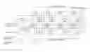
FIG. 1 is a schematic diagram of an annular time-to-digital converter provided by the present invention;
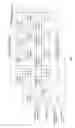
FIG. 2 is a schematic diagram of a differential comparing unit provided by the present invention;
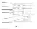
FIG. 3 is a flow diagram of an annular time-to-digital conversion method provided by the present invention.
DETAILED DESCRIPTION OF THE PREFERRED EMBODIMENTS
The technical solutions in the embodiments of the present invention will be clearly and completely described below in combination with the accompanying drawings in the embodiments of the present invention.
The present invention provides an annular time-to-digital converter, as shown in FIG. 1, mainly including:
a pulse shaper, having the effect of inputting a pulse of any width and converting the pulse of any width into a fixed-width pulse for output, and used for shaping an input start pulse and an input stop pulse to form fixed-width pulses for output;
at least two differential comparing units, as shown in FIG. 2, each differential comparing unit is a segment of a differential chain and consists of two buffers, a trigger, an AND gate and an OR gate, the delay difference of the two buffers is Tr, wherein delay is a long delay unit, buf is a short delay unit, the differential comparing units are used for enabling, during matching enabling, triggers of the differential comparing units to set setting ends to 1, and the trigger is an RS trigger and serves a result recording trigger in the differential comparing unit;
a circle counter, used for counting the number of times of propagating a pulse in a loop, wherein the circle counter is provided with two input ends, namely a Ci end and a Cr end, the Ci end is used for counting the number of circles of a long delay loop, and the Cr end is used for counting the number of circles of a short delay loop;
a matching enabling logical device, used for generating a matching enabling signal, and sending the generated matching enabling signal to comparing enabling ports of the differential comparing units;
at least two in-loop position encoders, used for determining a matching position of a matched unit according to matching signals sent by the differential comparing units; and
result recording registers, used for recording the number of circles of propagating a pulse in a loop and the matching position when matching occurs.
The AND gate in each differential comparing unit is used for performing logical AND processing on the outputs of the two buffers and the matching enabling signal and sending to the setting end of the trigger.
The matching enabling logical device is an RS trigger, and generates the matching enabling signal when the numbers of circles counted by the Ci end and the Cr end are equal.
The present invention further provides an annular time-to-digital conversion method, as shown in FIG. 3, including:
S1, inputting a start pulse and a stop pulse at two input ends of a pulse shaper respectively, and shaping the start pulse and the stop pulse to form fixed-width pulses for output;
S2, sending the output start pulse and the output stop pulse to a long delay loop and a short delay loop respectively;
S3, when the rising edge of the start pulse arrives at the Ci end of a circle counter, adding 1 to the Ci end of the circle counter;
when the rising edge of the stop pulse arrives at the Cr end of the circle counter, adding 1 to the Cr end of the circle counter;
S4, when the Ci end of the circle counter is equal to the Cr end, generating, by a matching enabling logical device, a matching enabling signal, setting, by triggers of differential comparing units, setting ends to 1, recording a matching position of a matched unit, and sending the generated matching enabling signal to comparing enabling ports of the differential comparing units; and
S5, transmitting the matching enabling signal through a matching transmission chain, and recording, by result recording registers, the count value in the circle counter and in-loop position encoding values.
The method further includes a step of initializing an annular time-to-digital converter before step S1, and the method of initializing the annular time-to-digital converter includes:
resetting the triggers in the annular time-to-digital converter, and cutting off and resetting loops through And gates at the entrances of a long delay loop and a short delay loop.
The circle counter sends the count value to a first result recording register Y for recording;
in-loop position encoders send in-loop position encoding values to a second result recording register X according to matching signal output codes for recording.
The above embodiments are merely used for describing the present invention, rather than limiting the present invention. Various modifications and variations may also be made by those of ordinary skill in the relevant technical field without departing from the spirit and scope of the present invention. Accordingly, all equivalent technical schemes fall into the scope of the present invention, and the patent protection scope of the present invention shall be defined by the claims.
Claims
1. An annular time-to-digital converter, comprising:
a pulse shaper, used for shaping an input start pulse and an input stop pulse to form fixed-width pulses for output;
at least two differential comparing units, used for enabling, during matching enabling, triggers of the differential comparing units to set setting ends to 1;
a circle counter, used for counting the number of circles of propagating a pulse in a loop;
a matching enabling logical device, used for generating a matching enabling signal, and sending the generated matching enabling signal to comparing enabling ports of the differential comparing units;
at least two in-loop position encoders, used for determining a matching position of a matched unit according to matching signals sent by the differential comparing units; and
result recording registers, used for recording the number of circles of propagating a pulse in a loop and the matching position when matching occurs.
2. The annular time-to-digital converter of claim 1, wherein each differential comparing unit consists of two buffers, a trigger, an AND gate and an OR gate.
3. The annular time-to-digital converter of claim 2, wherein the delay difference of the two buffers is Tr.
4. The annular time-to-digital converter of claim 2, wherein the AND gate in each differential comparing unit is used for performing logical AND processing on the outputs of the two buffers and the matching enabling signal and sending to the setting end of the trigger.
5. The annular time-to-digital converter of claim 2, wherein the trigger is an RS trigger.
6. The annular time-to-digital converter of claim 1, wherein the circle counter is provided with two input ends, respectively a Ci end and a Cr end, wherein the Ci end is used for counting the number of circles of a long delay loop, and the Cr end is used for counting the number of circles of a short delay loop.
7. The annular time-to-digital converter of claim 1, wherein the matching enabling logical device is an RS trigger, and generates the matching enabling signal when the numbers of circles counted by the Ci end and the Cr end are equal.
8. An annular time-to-digital conversion method, comprising:
S1, inputting a start pulse and a stop pulse at two input ends of a pulse shaper respectively, and shaping the start pulse and the stop pulse to form fixed-width pulses for output;
S2, sending the output start pulse and the output stop pulse to a long delay loop and a short delay loop respectively;
S3, when the rising edge of the start pulse arrives at the Ci end of a circle counter, adding 1 to the Ci end of the circle counter;
when the rising edge of the stop pulse arrives at the Cr end of the circle counter, adding 1 to the Cr end of the circle counter;
S4, when the Ci end of the circle counter is equal to the Cr end, generating, by a matching enabling logical device, a matching enabling signal, setting, by triggers of differential comparing units, setting ends to 1, recording a matching position of a matched unit, and sending the generated matching enabling signal to comparing enabling ports of the differential comparing units;
S5, transmitting the matching enabling signal through a matching transmission chain, and recording, by result recording registers, the count value in the circle counter and in-loop position encoding values.
9. The method of claim 8, further comprising a step of initializing an annular time-to-digital converter before step S1.
10. The method of claim 9, wherein the method of initializing the annular time-to-digital converter comprises:
resetting the triggers in the annular time-to-digital converter, and cutting off and resetting loops through And gates at the entrances of a long delay loop and a short delay loop.
11. The method of claim 8, wherein in step S5, the circle counter sends the count value to a first result recording register;
Images & Drawings included:
Sources:
- United States Patent and Trademark Office - verify current appl. status at the USPTO↗
Recent applications in this class:
- » 20250164938 2025-05-22
ERGODIC TIME TO DIGITAL CONVERTER - » 20250147468 2025-05-08
TIME TO DIGITAL CONVERTER (TDC) CIRCUIT WITH SELF-ADAPTIVE TIME GRANULARITY AND RELATED METHODS - » 20250123596 2025-04-17
METHODS AND APPARATUS FOR A TIME-TO-DIGITAL CONVERTER - » 20250110450 2025-04-03
ELECTRONIC CIRCUIT, DISTANCE MEASUREMENT DEVICE, AND EQUIPMENT - » 20250093822 2025-03-20
Multi-Chain Measurement Circuit - » 20250021055 2025-01-16
USING TIME-TO-DIGITAL CONVERTERS TO DELAY SIGNALS WITH HIGH ACCURACY AND LARGE RANGE - » 20240411273 2024-12-12
Method and Apparatus for Measuring Time - » 20240393746 2024-11-28
TIME TO DIGITAL CONVERSION - » 20240361729 2024-10-31
TIME-TO-DIGITAL CONVERTERS (TDC) EMPLOYING A SINGLE-STAGE DELAY PAIR AND NOISE SHAPING FOR WIDE INPUT RANGE AND REDUCED QUANTIZATION NOISE IN A PHASE-LOCKED LOOP (PLL) - » 20240272589 2024-08-15
TIME-TO-DIGITAL CONVERTER CIRCUIT