Robotic catheter system with FFR integration
US20160136392A1
2016-05-19
14/885,968
2015-10-16
✅ Patent granted
US 10,271,910 B2
2019-04-30
-
-
Eric J Messersmith
Rathe Lindenbaum LLP
2037-03-11
Abstract:
A method includes obtaining a fractional flow reserve (FFR) value over a given distance in a patient's vasculature; providing a display of a region of interest of the patient's vasculature; displaying a graphic on the display of the location of the vasculature having a FFR value outside of a predetermined limit; and robotically positioning a medical elongated device proximate the location.
Inventors:
- Tal Wenderow 48 🇺🇸 Newton, MA, United States
- Jeffrey Lightcap 10 🇺🇸 Plandome, NY, United States
Assignee:
- CORINDUS, INC. 89 🇺🇸 Waltham, MA, United States
Applicant:
Interested in similar patents?
Get notified when new applications in this technology area are published.
Classification:
A61M25/0116 » CPC main
Catheters; Hollow probes; Introducing, guiding, advancing, emplacing or holding catheters; Steering means as part of the catheter or advancing means; Markers for positioning self-propelled, e.g. autonomous robots
A61M2025/0166 » CPC further
Catheters; Hollow probes; Introducing, guiding, advancing, emplacing or holding catheters; Steering means as part of the catheter or advancing means; Markers for positioning Sensors, electrodes or the like for guiding the catheter to a target zone, e.g. image guided or magnetically guided
A61M25/01 IPC
Catheters; Hollow probes Introducing, guiding, advancing, emplacing or holding catheters
A61F2/958 » CPC further
Filters implantable into blood vessels; Prostheses, i.e. artificial substitutes or replacements for parts of the body; Appliances for connecting them with the body; Devices providing patency to, or preventing collapsing of, tubular structures of the body, e.g. stents; Instruments specially adapted for placement or removal of stents or stent-grafts Inflatable balloons for placing stents or stent-grafts
A61M2025/0002 » CPC further
Catheters; Hollow probes for pressure measurement with a pressure sensor at the distal end
A61B6/00 IPC
Apparatus for radiation diagnosis, e.g. combined with radiation therapy equipment
A61B6/504 » CPC further
Apparatus for radiation diagnosis, e.g. combined with radiation therapy equipment; Clinical applications involving diagnosis of blood vessels, e.g. by angiography
A61B6/12 » CPC further
Apparatus for radiation diagnosis, e.g. combined with radiation therapy equipment Devices for detecting or locating foreign bodies
A61B6/507 » CPC further
Apparatus for radiation diagnosis, e.g. combined with radiation therapy equipment; Clinical applications involving determination of haemodynamic parameters, e.g. perfusion CT
A61B6/5217 » CPC further
Apparatus for radiation diagnosis, e.g. combined with radiation therapy equipment; Devices using data or image processing specially adapted for radiation diagnosis involving processing of medical diagnostic data extracting a diagnostic or physiological parameter from medical diagnostic data
A61B6/461 » CPC further
Apparatus for radiation diagnosis, e.g. combined with radiation therapy equipment with special arrangements for interfacing with the operator or the patient Displaying means of special interest
A61B2034/301 » CPC further
Computer-aided surgery; Manipulators or robots specially adapted for use in surgery; Surgical robots for introducing or steering flexible instruments inserted into the body, e.g. catheters or endoscopes
A61B2090/064 » CPC further
Instruments, implements or accessories specially adapted for surgery or diagnosis and not covered by any of the groups - , e.g. for luxation treatment or for protecting wound edges; Measuring instruments not otherwise provided for for measuring force, pressure or mechanical tension
A61M2205/502 » CPC further
General characteristics of the apparatus with microprocessors or computers User interfaces, e.g. screens or keyboards
A61M2230/30 » CPC further
Measuring parameters of the user Blood pressure
A61B5/02 IPC
Measuring for diagnostic purposes ; Identification of persons Detecting, measuring or recording pulse, heart rate, blood pressure or blood flow; Combined pulse/heart-rate/blood pressure determination; Evaluating a cardiovascular condition not otherwise provided for, e.g. using combinations of techniques provided for in this group with electrocardiography or electroauscultation; Heart catheters for measuring blood pressure
A61B34/30 » CPC main
Computer-aided surgery; Manipulators or robots specially adapted for use in surgery Surgical robots
A61M25/00 IPC
Probes; Catheters; Dilators; Drainage appliances for wounds
A61M25/00 IPC
Catheters; Hollow probes
A61B90/00 IPC
Instruments, implements or accessories specially adapted for surgery or diagnosis and not covered by any of the groups - , e.g. for luxation treatment or for protecting wound edges
Description
CROSS REFERENCE TO RELATED APPLICATIONS
This application claims priority to U.S. Provisional Patent Application No. 62/064,760 entitled ROBOTIC CATHETER SYSTEM WITH FFR INTEGRATION and filed on Oct. 16, 2014 which is incorporated herein by reference in its entirety.
BACKGROUND OF THE INVENTION
Systems exist for the robotic feeding of percutaneous interventional devices such as guide wires and working catheters into guide catheters and procedures exist for the placement and seating of guide catheters such that their distal ends are adjacent the site of action for the intervention, typically a valve or chamber of the heart or a lesion in a blood vessel such as an artery. The guide catheter is typically placed by manual manipulation of medical personnel and its continued seating after placement assumed or determined by feel. The interventional devices such as guide wires and working catheters may be fed by the operation of robotic controls by medical personnel such as shown in U.S. Pat. No. 7,887,549 incorporated herein by reference in its entirety.
SUMMARY OF THE INVENTION
A robotic catheterization apparatus is used with FFR technology to aid in the selection and/or placement of the stent within a vasculature of a patient.
A method includes obtaining a fractional flow reserve (FFR) value over a given distance in a patient's vasculature; providing a display of a region of interest of the patient's vasculature; displaying a graphic on the display of the location of the vasculature having a FFR value outside of a predetermined limit; and robotically positioning a medical elongated device proximate the location.
An apparatus includes a robotic drive system including a linear drive mechanism. A fractional flow reserve system including a device to calculate a fractional flow (FFR) value over a given distance in a patient's vasculature. A display provides a real time graphic of a patient's vasculature including a display of the FFR value for a region of interest.
BRIEF DESCRIPTION OF THE DRAWINGS
This application will become more fully understood from the following detailed description, taken in conjunction with the accompanying figures, wherein like reference numerals refer to like elements in which:
FIG. 1 is a schematic of the environment in which percutaneous interventional procedures are robotically performed.
FIG. 2 is a schematic view of an FFR integration system and the robotic catheter system.
FIG. 3 is a schematic view of an integration system and a remote station.
FIG. 4 is a schematic view of a display with an FFR value and identified region over which the FFR value represents.
DETAILED DESCRIPTION OF THE PREFERRED EMBODIMENTS
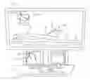
FIG. 1 shows the environment in which the various embodiments of the present invention find particular utility. It shows a catheter laboratory 10 for robotically performing percutaneous interventional procedures. A patient 11 is supported on a table 14 and the procedure is observed with X-ray equipment 12. A cassette 22 supported by a robotic arm 20 is used to automatically feed a guide wire 30 (shown in FIG. 2) into a guide catheter 32 seated in an artery of the patient 11. The cassette 22 is controlled from a remote station 24 in order to isolate the medical personnel conducting the procedure from exposure to the X-ray radiation used to monitor the procedure by use of fluoroscopic equipment. The station includes remote controls 26 for controlling the cassette 22 and a screen 28 with which to monitor the progress of the procedure. It displays the arterial system 29 being addressed by the procedure. U.S. Pat. No. 7,887,549, incorporated herein by reference, has a detailed disclosure of this environment.
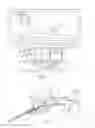
Referring to FIG. 2 cassette 22 drives guide wire 30 and/or a working catheter 34 such as a balloon and/or stent catheter through a guide catheter 32. A drive mechanism is housed in cassette 22 that provides translational and/or rotational movement to the guide wire and/or working catheter.
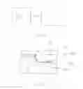
Referring to FIG. 3 an integration system 40 is incorporated into remote station 24. In another embodiment integration system 40 is standalone system that communicates with remotes station 24 either wirelessly or through a wired connection such as a cable.
In one embodiment an integration system 40 receives data from a computer tomography (CT) system that includes CT scan data of a given patient. In one embodiment the CT scan data includes three dimensional data that provides a three dimensional array of the patient or a region of interest that is a portion of the patient anatomy of interest.
Integration system 40 using fractional flow reserve (FFR) technology can perform analysis on the CT data to determine areas within the vasculature of a patient that has reduced blood flow and/or reduced blood pressure. FFR technology is sued to identify pressure differences between various locations within a patient's vasculature. FFR is the ratio of maximum blood flow at one location to the normal maximum flow in the same vessel. Stated another way FFR=Pd/Pa where Pd=pressure distal to a lesion and Pa=normal pressure proximal to the lesion. The two points in which the pressure is identified is typically at a point before a stenosis lesion and after the stenosis lesion. In one embodiment FFR is provided as an absolute number representing the drop in blood pressure across a lesion.
In one implementation the information provided by FFR is used in conjunction with the graphical information provided during a percutaneous coronary intervention procedure. For example the graphical information of a vasculature that is obtained during a guide wire and/or a catheter procedure may be obtained by fluoroscopy or other known imaging systems and displayed in real time on a display for an operator. In one embodiment the FFR values for the region of interest are superimposed onto the graphical display of the vasculature region of interest to aid an operator in the placement of the stent utilizing the robotic catheter system. The region of interest is identified on the display and is superimposed by a graphic to indicate the region over which a FFR value has been obtained and calculated.
There are various methods for determining the FFR. In one method a pressure sensor is driven through a patient's vasculature on an elongated medical device. The pressure information can be conveyed back to the remote station 24. FFR values can be calculated based on points of interest identified by an operation of the robotic catheter system. The points may be identified by the use of an interface device such as a mouse by selecting two points on the display of the patient's vasculature. In one embodiment the blood pressure values are transmitted in real time so that the blood pressure is associated with a point in the vasculature which is stored within remote station 24.
In one implementation an elongated medical device 32 includes a proximal end and a distal end that is inserted into a vasculature of a patient. This device will be identified herein as the FFR Device. A pressure sensor is positioned proximate the distal free end of the FFR Device. The distal end is the end that is the free end in the vasculature, while the proximal end is the end opposite the distal end and outside of the vasculature when the distal end is within the vasculature.
Blood pressure values are obtained by the pressure sensor as the FFR Device is moved through the vasculature system. The blood pressure values are transmitted to an FFR processing station and the values are stored for further processing. Transmission of the blood pressure values from the blood pressure sensor in one implementation is electronically via a signal along the FFR Device. In another implementation, transmission of the data is done digitally either along the FFR Device or wirelessly.
The location of the distal end of the FFR Device is identified as a location within the vasculature by superimposing the location of the FFR Device blood pressure value with the location of the vasculature at the time the measurement was taken. An algorithm using the graphical display information obtained by an imaging system such as fluoroscopy associates the blood pressure value with a specific location in the vasculature. In one embodiment blood flow pressure information is transmitted continuously as the pressure sensor is moved through the vasculature. In one embodiment blood flow pressure information obtained from the pressure sensor is taken periodically based on a discrete movement of the FFR Device within the vasculature such that a pressure measurement is obtained every predetermined movement of the distal end of the FFR Device within the vasculature. In one embodiment the frequency of obtaining and transmitting blood pressure values is automatically revised based on the change of blood pressure from the previous readings. In this manner it is possible to identify the specific location of stenosis of interest. In one embodiment the change of blood pressure value of interest is set by an operator. As an example an operator may set a change of blood pressure of 5% that is a 5% reduction from a first location to a second location being at least a predetermined distance as way as being a value of interest. Once that threshold is identified, the frequency of measurements are increased over smaller distances so that the specific region of interest suggesting a stenosis or lesion is properly identified. It is also contemplated that once the threshold value is identified, the system automatically withdraws the FFR Device to the first location and obtains additional pressure readings as the FFR Device is once again moved forward or further into the vasculature of the patient. The operator may also set the change of blood pressure in terms of absolute pressure values and not as a percentage.
In one implementation a robotic linear drive mechanism 22 as disclosed in U.S. Pat. No. 7,887,549 linearly drives the distal end of the FFR Device into and out of the vasculature. The linear drive operates on a portion of the FFR Device intermediate the distal end and proximal end. In one implementation the robotic linear drive mechanism includes a rotational drive mechanism that operates to rotate the FFR Device along a longitudinal axis of the FFR Device. In one implementation a plurality of blood pressure value is obtained while the distal end of the FFR Device is in a fixed position within the vasculature. An average blood pressure value is determined by pressure measurements that are taken every fixed number of degrees. By example, in one embodiment the FFR Device is rotated 90 degrees four times and a blood pressure reading is obtained by a pressure sensor on the distal end of the FFR Device. The four readings are then averaged to obtain a blood pressure reading at a given location. The FFR Device is then moved an incremental linear unit and four additional pressure readings are obtained at 90 degree rotations of the FFR Device. It is contemplated that the number of readings and degree of rotation may be varied. It is also contemplated that at algorithm may be used to determine the appropriate blood pressure value based on the multiple pressure readings obtained at a given location.
In one embodiment, an algorithm identifies the likely region of a stenosis or lesion for operator analysis by use of a graphic superimposed on the display of the patient's vasculature illustrating the likely region of stenosis or legion. The length of the region of reduced blood pressure can aid in the operator in the selection of a proper sized stent to cover the area of interest.
In one embodiment a simulation module calculates the FFR values over a particular area of interest in the patient's vasculature. In one embodiment the simulation module determines an ideal location within the patient's vasculature to place a stent. In one embodiment the simulation module further determines one of or all of the type of stent, diameter of the stem, and length of the stent to optimize the FFR value after the stent has been placed within the patient's vasculature so that the blood flow post stent placement has been optimized.
In one implementation the FFR Device is incorporated into a balloon stent catheter such that a blood flow pressure reading is obtained as the balloon stent catheter is moved into position proximate a narrowing of the vasculature to be treated.
In one embodiment the integration module receives FFR values derived from a previously acquired CT scan of the patient in question. The FFR values are superimposed onto the x-ray views that are displayed on a display at the remote station. In one embodiment the FFR values are superimposed in real time as the x-ray images are acquired and displayed.
The simulation module via the use of an algorithm identifies the type and size of the stent required to maximize FFR readings post stent placement. In one embodiment the simulation module identifies the location for position of the stent based on FFR readings during real time of stent placement. The location for position of the stent can include a single point or can identify on the display the location that one end of the stent should be place before the stenosis and the location that the second end of the stent should be place beyond the stenosis.
In one embodiment the integration module includes a close loop navigation control based on the superimposed CT image and the real time X-ray tracking (or other tracking means) to optimize stent positioning using the robotic system. In one embodiment the position of the stent is verified to the pre acquired CT to make sure it provides the largest clinical outcome from this specific stent position. In one embodiment post deployment of the stent FFR measurements are made (invasive or through x-ray FFR) to verify flow and good clinical outcomes.
While the foregoing written description of the invention enables one of ordinary skill to make and use what is considered presently to be the best mode thereof, those of ordinary skill will understand and appreciate the existence of variations, combinations, and equivalents of the specific embodiment, method, and examples herein. The invention should therefore not be limited by the above described embodiment, method, and examples, but by all embodiments and methods within the scope and spirit of the invention as claimed.
Claims
What is claimed is:1. A method comprising:
obtaining a fractional flow reserve (FFR) value over a given distance in a patient's vasculature;
providing a display of a region of interest of the patient's vasculature;
displaying a graphic on the display of a location of the vasculature having a FFR value outside of a predetermined limit; and
robotically positioning a medical elongated device proximate the location.
2. The method of claim 1, wherein the FFR value is defined as Pd/Pa where Pd is a first blood flow pressure at a first location within the vasculature and Pa is a second blood flow pressure at a second location within the vasculature.
3. The method of claim 2, wherein obtaining an FFR value includes obtaining the first blood flow pressure value with an FFR elongated medical device having a pressure sensor on a distal end thereof.
4. The method of claim 1, further including controlling the distance between blood flow pressure readings within a vasculature based on a predetermined algorithm.
5. The method of claim 4, wherein the distance between blood flow pressure readings is determined automatically by a processor as a function of the rate of change of blood flow pressure per incremental unit travel within the vasculature.
6. The method of claim 3, further including robotically controlling the linear movement of the FFR elongated medical device with a robotically controlled drive mechanism.
7. The method of claim 6, further including robotically controlling the rotational movement of the FFR elongated medical device with the robotically controlled drive mechanism.
8. The method of claim 6, further including automatically withdrawing the distal end of the FFR elongated medical device a distance within the vasculature and reinserting the FFR elongated medical device and robotically controlling the linear movement of the FFR elongated medical device with a robotically controlled drive mechanism.
9. The method of claim 1, further including obtaining the blood flow pressure at a given location within the vasculature including calculating an average blood flow pressure as a function of multiple blood flow pressure readings at different rotational orientation of the blood flow pressure sensor.
10. The method of claim 1, wherein the FFR values are obtained from a computerized tomography (CT) scan.
11. The method of claim 1, wherein the FFR values are obtained with an elongated medical device having a pressure sensor on a distal end thereof.
12. The method of claim 11, further including a processor identifying a region of stenosis as a function of FFR values within the vasculature.
13. An apparatus comprising:
a robotic drive system including a linear drive mechanism;
a fractional flow reserve system including a device to calculate a fractional flow (FFR) value over a given distance in a patient's vasculature; and
a display providing a real time graphic of a patient's vasculature including a display of the FFR value for a region of interest in the patient's vasculature.
14. The apparatus of claim 13 wherein the device to calculate the FFR value includes an elongated medical device having a pressure sensor at a distal end thereof.
15. The apparatus of claim 14 including a controller providing instructions to the robotic drive system to drive the elongated medical device having the pressure sensor to move in a predetermined distance and obtain a pressure reading.
16. The apparatus of claim 15 wherein the robotic drive system includes a rotational drive mechanism to rotate the elongated medical device about its longitudinal axis at a predetermined angle at a given location within the vasculature.
17. The apparatus of claim 15 wherein the controller provides instructions to the robotic drive system based on an algorithm to automatically withdraw the distal end of the FFR elongated medical device a distance within the vasculature and reinserting the device further including robotically controlling the linear movement of the FFR elongated medical device with a robotically controlled drive mechanism
18. The apparatus of claim 13 wherein the controller provides instructions to display the region over which a FFR value was calculated at a stenosis in the vasculature.
19. The apparatus of claim 18 wherein the controller automatically positions a balloon stent catheter within the vasculature as a function of the FFR value.
20. The apparatus of claim 13 wherein the robotic drive system includes a linear drive mechanism and rotational drive mechanism.
Images & Drawings included:
Sources:
- United States Patent and Trademark Office - verify current appl. status at the USPTO↗
Recent applications in this class:
- » 20250213819 2025-07-03
ACTUATOR POWER APPARATUS AND SURGERY ASSISTANCE SYSTEM - » 20250186742 2025-06-12
MEDICAL DEVICES WITH DISTAL CONTROL - » 20250161633 2025-05-22
DETACHABLE URETHRAL CATHETERIZATION DEVICE - » 20250010034 2025-01-09
CONTROL SYSTEM, CONTROL DEVICE, CONTROL METHOD, AND PROGRAM - » 20240408355 2024-12-12
ROBOTIC CATHETERISATION SYSTEM, ASSOCIATED CATHETER ROBOT, CONTROL INTERFACE AND METHOD FOR OPERATING A ROBOTIC CATHETERISATION SYSTEM - » 20240382716 2024-11-21
MODULE FOR TRANSLATING A PLURALITY OF ELONGATE FLEXIBLE MEDICAL INSTRUMENTS, COMPRISING A DEVICE FOR CONVERGENCE TOWARDS A COMMON TRACK - » 20240198051 2024-06-20
SYSTEM AND METHOD OF PERFORMING A ROBOTIC AND MANUAL VASCULAR PROCEDURE - » 20220143366 2022-05-12
SYSTEMS AND METHODS FOR DETERMINING BUCKLING AND PATIENT MOVEMENT DURING A MEDICAL PROCEDURE - » 20210236773 2021-08-05
Autonomous robotic catheter for minimally invasive interventions - » 20210236772 2021-08-05
System for monitoring and maintaining an intravascular assembly
Recent applications for this Assignee:
- » 20220088349 2022-03-24
Robotic catheter system with variable speed control - » 20220001142 2022-01-06
HEMOSTASIS VALVE FOR GUIDE CATHETER CONTROL - » 20210361366 2021-11-25
Occlusion traversal robotic catheter system - » 20210353376 2021-11-18
Interlocking system and method for joysticks in a catheter procedure system - » 20210220064 2021-07-22
Remote communications and control system for robotic interventional procedures - » 20210100980 2021-04-08
System for guide catheter control with introducer connector - » 20210093406 2021-04-01
System and method for navigating a guide wire - » 20210077211 2021-03-18
System and method for navigating a guide wire - » 20210060767 2021-03-04
System and method for controlling a position of an articulated robotic arm - » 20210030492 2021-02-04
Robotic catheter system with variable drive mechanism