Wind turbine with a rotor positioning system
US20160195069A1
2016-07-07
14/968,150
2015-12-14
✅ Patent granted
US 10,240,582 B2
2019-03-26
-
-
Jason D Shanske | Maxine M Adjagbe
Ladas & Parry LLP
2037-10-29
Abstract:
The invention provides a wind turbine having a system for positioning the rotor in an azimuthal reference position Azref and for maintaining it therein for a predetermined period of time, the wind turbine being arranged in test mode. Said rotor positioning system comprises a first controller (31) configured to generate a generator speed reference Ωref from the difference between the rotor azimuthal reference position Azref and the rotor azimuthal measured position Azmeas and a second controller (35) configured to generate a generator torque reference Tref from the difference between said generator speed reference Ωref and the generator speed measured Ωmeas.
Assignee:
- GAMESA INNOVATION & TECHNOLOGY, S. L. 11 🇪🇸 SARRIGUREN (NAVARRA), Spain
- GAMESA INNOVATION & TECHNOLOGY, S. L. 11 🇪🇸 Sarriguren (Navarra), Spain
Applicant:
Interested in similar patents?
Get notified when new applications in this technology area are published.
Classification:
F03D9/00 IPC
Adaptations of wind motors for special use; Combinations of wind motors with apparatus driven thereby; Wind motors specially adapted for installation in particular locations
F03D7/0276 » CPC main
Controlling wind motors the wind motors having rotation axis substantially parallel to the air flow entering the rotor Controlling rotor speed, e.g. variable speed
F03D1/0675 » CPC further
Wind motors with rotation axis substantially parallel to the air flow entering the rotor ; Rotors characterised by their construction, i.e. structural design details of the blades
F03D1/0691 » CPC further
Wind motors with rotation axis substantially parallel to the air flow entering the rotor ; Rotors characterised by their construction, i.e. structural design details of the hub
F03D7/0224 » CPC further
Controlling wind motors the wind motors having rotation axis substantially parallel to the air flow entering the rotor; Adjusting aerodynamic properties of the blades Adjusting blade pitch
F03D7/0272 » CPC further
Controlling wind motors the wind motors having rotation axis substantially parallel to the air flow entering the rotor by measures acting on the electrical generator
F03D7/043 » CPC further
Controlling wind motors the wind motors having rotation axis substantially parallel to the air flow entering the rotor; Automatic control; Regulation by means of an electrical or electronic controller characterised by the type of control logic
F03D7/04 IPC
Controlling wind motors the wind motors having rotation axis substantially parallel to the air flow entering the rotor Automatic control; Regulation
F03D7/02 IPC
Controlling wind motors the wind motors having rotation axis substantially parallel to the air flow entering the rotor
F03D1/06 IPC
Wind motors with rotation axis substantially parallel to the air flow entering the rotor Rotors
F03D80/82 » CPC further
Details, components or accessories not provided for in groups -; Arrangement of components within nacelles or towers of electrical components
F03D9/25 IPC
Adaptations of wind motors for special use; Combinations of wind motors with apparatus driven thereby; Wind motors specially adapted for installation in particular locations; Wind motors characterised by the driven apparatus the apparatus being an electrical generator
F05B2270/1032 » CPC further
Control; Purpose of the control system to affect the output of the engine Torque
F03D7/0268 » CPC further
Controlling wind motors the wind motors having rotation axis substantially parallel to the air flow entering the rotor for stopping or in emergency situation Parking or storm protection
F03D9/255 » CPC further
Adaptations of wind motors for special use; Combinations of wind motors with apparatus driven thereby; Wind motors specially adapted for installation in particular locations; Wind motors characterised by the driven apparatus the apparatus being an electrical generator connected to an electrical general supply grid; Arrangements therefor
F03D80/50 » CPC further
Details, components or accessories not provided for in groups - Maintenance or repair
F03D7/044 » CPC further
Controlling wind motors the wind motors having rotation axis substantially parallel to the air flow entering the rotor; Automatic control; Regulation by means of an electrical or electronic controller characterised by the type of control logic with PID control
F05B2270/32 » CPC further
Control; Control parameters, e.g. input parameters Wind speeds
F05B2270/326 » CPC further
Control; Control parameters, e.g. input parameters Rotor angle
F05B2270/705 » CPC further
Control; Type of control algorithm proportional-integral
F05B2270/706 » CPC further
Control; Type of control algorithm proportional-integral-differential
F03D17/00 » CPC further
Monitoring or testing of wind motors, e.g. diagnostics
F03D80/80 IPC
Details, components or accessories not provided for in groups - Arrangement of components within nacelles or towers
F03D13/20 » CPC further
Assembly, mounting or commissioning of wind motors; Arrangements specially adapted for transporting wind motor components Arrangements for mounting or supporting wind motors; Masts or towers for wind motors
F05B2260/83 » CPC further
Function Testing, e.g. methods, components or tools therefor
F05B2270/327 » CPC further
Control; Control parameters, e.g. input parameters Rotor or generator speeds
Description
FIELD OF THE INVENTION
The invention relates to a rotor positioning system of a wind turbine.
BACKGROUND
Over the life of wind turbines there are several tasks that must maintain fixed the rotor in a certain position.
One of these tasks is the rotor locking to ensure it does not rotate which is needed to perform certain maintenance activities. Rotor locking systems typically comprise one or more pins (often two pins) which are pushed into holes in the stationary part of the wind turbine to prevent rotation of the rotor and therefore require a system to position the rotor so that the pins are perfectly aligned with the holes. The rotor locking process is difficult and time consuming. This task is even more complex when the wind speed increases and become impossible above certain wind speed.
Another of these tasks is the access of service personnel transported by helicopters to offshore wind turbines that have helihoist platforms where is needed to have the rotor stationary while the helicopter is nearby.
Another of these tasks is the calibration of the blade load sensors where the rotor shall be maintained fixed in various positions (and also having the blades at different pitch angles in each position) to compare the calibration with the static moments in said positions.
All these tasks must be performed in narrow ranges of time and within a wide range of speeds.
Known rotor positioning systems for such tasks have a high manual component and do not therefore allow a remote operation which would be very desirable especially in offshore wind turbines.
SUMMARY OF THE INVENTION
The invention provides a wind turbine having a system for positioning the rotor in an azimuthal reference position Azref and for maintaining it therein for a predetermined period of time, the wind turbine being arranged in test mode, so that during that period of time the tasks mentioned in the previous section can be carried out. This system comprises a first controller configured to generate a generator speed reference Ωref from the difference between the rotor azimuthal reference position Azref and the rotor azimuthal measured position Azmeas and a second controller configured to generate a generator torque reference Tref from the difference between said generator speed reference Ωref and the generator speed measured Ωmeas.
The first and/or the second controller can be PI (Proportional, Integral) controllers or PID (Proportional, Integral, Derivative) controllers being its variable gains dependent of the wind speed Vmeas measured at the height of the rotor hub.
The wind turbine comprises an Uninterruptible Power Supply (UPS) device or a connection to a power grid to provide power to the generator when acting as a motor under the control of the rotor positioning system.
Other features and advantages of the present invention will be understood from the following detailed description of illustrative and by no means limiting embodiments of its object in relation with the enclosed drawings.
BRIEF DESCRIPTION OF THE FIGURES
FIG. 1 is a schematic cross sectional view of a wind turbine.
FIG. 2 is a schematic block diagram illustrating an embodiment of the rotor positioning system according to the invention with two PI controllers.
FIGS. 3-6 are schematic block diagrams illustrating how the proportional and integral gains of the two PI controllers are obtained.
FIG. 7 illustrates the operation of the rotor positioning system to place it in the azimuthal position 90 deg.
DETAILED DESCRIPTION OF THE INVENTION
A typical wind turbine 11 comprises a tower 13 supporting a nacelle 21 that houses a generator 19 for converting the rotational energy of the wind turbine rotor into electrical energy. The wind turbine rotor comprises a rotor hub 15 and, typically, three blades 17. The rotor hub 15 is connected either directly or through a gearbox to the generator 19 of the wind turbine for transferring the torque generated by the rotor to the generator 19 and increase the shaft speed in order to achieve a suitable rotational speed of the generator rotor.
The wind turbine 11 also comprises means allowing the generator 19 acting as a motor receiving power from a suitable source such as an Uninterruptible Power Supply (UPS) device available in the own wind turbine 11 or an electricity grid to which the turbine 11 is connected. Thus, the generator 19 can be used as a rotor driving means.
The wind turbine power output is controlled by means of a control system for regulating the pitch angle of the rotor blades and the generator torque. The rotor rotational speed and power output of the wind turbine can hereby be controlled.
For implementing said regulation the control system receives input data such as wind speed V, generator speed Ω, pitch angle θ, power P from well-known measuring devices and send output data θref, Tref to, respectively, the pitch actuator system for changing the pitch of the blades 17 and to a generator command unit for changing the torque reference for the power production.
According to the invention the wind turbine 11 also comprises a rotor positioning system which allows placing it in a particular position, being the wind turbine 11 in test mode, i.e. when the wind turbine does not produces energy, the rotor and the power train rotate freely by the wind action and the brake system is disabled.
That particular position is expressed in terms of an azimuthal reference position Azref. For example, the azimuthal position 0 deg means that the blade 1 of the wind turbine 11 has its tip pointing to the sky, the azimuthal position 90 deg means that, looking at the wind turbine from outside and from an observer in front of it, the blade 1 would be rotated clockwise 90 deg and the azimuthal position 180 deg means that the blade 1 is pointing to the ground. The azimuthal position of the rotor is measured by a sensor located on the low speed side of the drive train which generates a pulse when the blade 1 is in the azimuthal position 0 deg. Depending on the transmission ratio between the low speed shaft and the high speed shaft and this pulse the azimuthal position is calculated by integration.
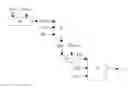
In one embodiment of the invention using PI (proportional integral) controllers the rotor positioning system (see FIG. 2) comprises:
-
- A first PI controller 31 that generates a generator speed reference Ωref from the azimuthal error Azerr, obtained in a module 29 which is configured to calculate it from the azimuthal reference position Azref and the azimuthal measured position Azmeas (by the above-mentioned sensor) and the proportional and integral gains Kp1 and Ki1 dependent on the wind speed V (measured with an anemometer located at the height of the rotor hub 15).
- A second PI controller 35 that generates a generator torque reference Tref from the generator speed error Ωerr, obtained in a module 33 which is configured to calculate it from the generator speed reference Ωref and the measured generator speed Ωmeas (upon application of a filter to remove high frequency components) and the proportional and integral gains Kp2 and Ki2.
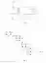
The proportional gain Kp1, expressed in rpm/deg, is obtained (see FIG. 3) in a module 43 which is configured to calculate it multiplying a variable gain value Δv1 dependent of the measured wind speed Vmean at the height of the rotor hub 15, averaged at 600 s, by a parameter P1, expressed in rpm/deg, which defines the proportional gain of the first PI controller 31. The value of the variable gain Δv1 is obtained in a module 41 which is configured to calculate it from Vmean using an interpolation table.
The integral gain Ki1, expressed in s*rpm/deg, is obtained (see FIG. 4) in a module 45 which is configured to calculate it from the proportional gain Kp1 and a parameter P2, expressed in s, which defines the integral time on the first proportional integral controller 31.
The proportional gain Kp2, expressed in Nm/rpm, is obtained (see FIG. 5) in a module 53 which is configured to calculate it multiplying a variable gain value Δv2 dependent of the measured wind speed Vmean at the height of the rotor hub 15, averaged at 600 s, by a parameter P3, expressed in Nm/rpm, which defines the proportional gain of the second PI controller 31. The variable gain value Δv2 is obtained in a module 51 which is configured to calculate it from Vmean using an interpolation table.
The integral gain Ki2, expressed in s*rpm/deg, is obtained (see FIG. 6) in a module 55 which is configured to calculate it from the proportional gain Kp2 and a parameter P4, expressed in s, which defines the integral time on the second proportional integral controller 35.
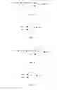
The following curves (see FIG. 7) illustrate the operation of the rotor positioning system to place it on the azimuthal position 90 deg:
-
- The curve 61 represents the azimuthal reference position Azref(90 deg).
- The curve 63 represents the evolution in time of the azimuthal measured position Azmeas.
- The curve 65 represents the evolution in time of the generator speed reference Ωref.
- The curve 67 represents the evolution in time of the measured generator speed Ωmeas.
- The curve 69 represents the evolution in time of the azimuthal error Azerr.
- The curve 71 represents the evolution in time of the generator torque reference Tref.
As shown, the rotor positioning system begins to demand an initial generator speed reference Ωref of 20 rpm (curve 65) and, since time t1, an azimuthal reference position Azref of 90 deg (curve 61).
Once the azimuthal measured position Azmeas (curve 63) matches the azimuthal reference position Azref (curve 61) at time t2, the controllers 31, 35 are activated to achieve the generator torque reference Tref (curve 71) needed to keep Azref at 90 deg. The azimuthal error Azerr reaches 0 at 200 s and the generator torque reference Tref varies with time taking positive and negative values.
The main advantage of the invention is that it allows automation of the wind turbine operation to maintain fixed the rotor in a given azimuthal position for some time to perform operations such as rotor blocking, personnel access to the wind turbine from helicopters and blade load sensors calibration.
Although the present invention has been described in connection with various embodiments, it will be appreciated from the specification that various combinations of elements, variations or improvements therein may be made, and are within the scope of the invention as defined by the appended claims.
Claims
1. A wind turbine (11) comprising:
a tower (13) and a nacelle (21) housing a generator (19) connected to a rotor comprising a rotor hub (15) and at least one blade (17), being the generator arranged (19) to act as a motor;
measuring devices of, at least, wind speed V, generator speed Ω and rotor azimuthal position Az;
a control system connected to said measuring devices and to at least pitch and torque control actuators;
characterized in that further comprises a system for positioning the rotor in an azimuthal reference position Azref and for maintaining it therein during a predetermined period of time, being the wind turbine (11) arranged in test mode, that comprises:
a first controller (31) configured to generate a generator speed reference Ωref from the difference between the rotor azimuthal reference position Azref and the rotor azimuthal measured position Azmeas;
a second controller (35) configured to generate a generator torque reference Tref from the difference between said generator speed reference Ωref and the generator speed measured Ωmeas.
2. A wind turbine (11) according to claim 1, wherein the first and second controllers (31, 35) are proportional integral controllers and their proportional and integral gains Kp1, Kp2; Ki1, Ki2 are dependent variables from the measured wind speed Vmeas at the height of the rotor hub (15).
3. A wind turbine (11) according to claim 2, wherein:
the proportional gain Kp1, expressed in rpm/deg, is obtained in a module (43) configured to calculate it from a variable gain value Δv1 dependent of the measured wind speed Vmean at the height of the rotor hub (15), averaged at 600 s, and a parameter P1, expressed in rpm/deg, defining the proportional gain of the first controller (31);
the integral gain Ki1 expressed in s*rpm/deg, is obtained in a module (45) configured to calculate it from the proportional gain Kp1 and a parameter P1 that defines the integral time s of the first proportional integral controller (31);
the proportional gain Kp2, expressed in Nm/rpm, is obtained in a module (53) configured to calculate it from a variable gain value Δv2 dependent of the measured wind speed Vmean at the height of the rotor hub (15), averaged at 600 s, and a parameter P3, expressed in Nm/rpm, defining the proportional gain of the second controller (35);
the integral gain Ki2 expressed in s*Nm/rpm, is obtained in a module (55) configured to calculate it from the proportional gain Kp2 and a parameter P4 that defines the integral time s of the second controller (35).
4. A wind turbine (11) according to claim 1, wherein the first and second controller (31, 35) are proportional, integral and derivative controllers and theirs proportional, integral and derivative gains are dependent variables of the measured wind speed Vmeas at the height of the rotor hub (15).
5. A wind turbine (11) according to claim 1, further comprising a Uninterruptible Power Supply (UPS) device for providing energy to the generator (19) when the wind turbine is test mode and the generator (19) acts as a motor.
6. A wind turbine (11) according to claim 1, further comprising a connection to an electricity grid to power the generator (19) when the wind turbine is in test mode and the generator (19) acts as a motor.
Images & Drawings included:
Sources:
- United States Patent and Trademark Office - verify current appl. status at the USPTO↗
Similar patent applications:
- » 20090162202
Braking and positioning system for a wind turbine rotor - » 20100135800
Systems and methods for determining the angular position of a wind turbine rotor - » 20180230970
System and method for determining an estimated position of a wind turbine rotor shaft - » 20200025170
System and method for reducing wind turbine loads by yawing the nacelle to a predetermined position based on rotor imbalance - » 20220186713
DISTRIBUTED SYSTEM FOR AND METHOD OF DETECTING POSITION AND/OR SPEED OF A ROTOR BLADE DURING OPERATION OF A WIND TURBINE - » 20230250803
Method and system of positive and negative sequence rotor currents control for doubly-fed induction generator-based wind turbines under single dq-PI control structure
Recent applications in this class:
- » 20160369777 2016-12-22
SYSTEM AND METHOD FOR DETECTING ANOMALY CONDITIONS OF SENSOR ATTACHED DEVICES - » 20160356266 2016-12-08
System and Method for Reducing Torsional Movement in a Wind Turbine Tower - » 20160169206 2016-06-16
ROTOR OF A WIND TURBINE - » 20160169205 2016-06-16
METHOD FOR CONSTRUCTING WIND POWER CONNECTION SYSTEM MODEL BASED ON MEASURED DATA - » 20160169204 2016-06-16
Static testing and calibrating method for PID link of control system of wind turbine - » 20160160842 2016-06-09
METHOD FOR DETERMINING THE LIFE OF COMPONENTS OF A WIND TURBINE OR SIMILAR ACCORDING TO ITS LOCATION - » 20160153427 2016-06-02
Balancing of wind turbine parts - » 20160146195 2016-05-26
Turbine fluid velocity field measurement - » 20160146194 2016-05-26
Apparatus for applying a load to an installed wind turbine blade and method of using the same - » 20160138571 2016-05-19
System and method for estimating rotor blade loads of a wind turbine
Recent applications for this Assignee:
- » 20180313327 2018-11-01
CONTROL METHOD FOR A WIND FARM, AND WIND FARM THEREOF - » 20180111805 2018-04-26
Crane of a wind turbine - » 20180111801 2018-04-26
Wind turbine blades lifting device and associated method - » 20180097347 2018-04-05
Lightning current transmission system for wind turbines - » 20170310233 2017-10-26
Three phase medium voltage power conversion system for coupling a power source to a utility grid - » 20170272004 2017-09-21
Three phase medium voltage power conversion system for closed-loop applications - » 20170241152 2017-08-24
REINFORCED WIND TOWER - » 20170179727 2017-06-22
Power generation system of a multi-converter wind turbine and control method thereof - » 20170153286 2017-06-01
Methods and systems for real-time monitoring of the insulation state of wind-powered generator windings - » 20170145988 2017-05-25
Wind turbine blade comprising a lightning protection system equipped with radar absorbing material