Reducing the load consumed by gas turbine compressor and maximizing turbine mass flow
US20160376985A1
2016-12-29
14/392,074
2013-05-30
✅ Patent granted
US 10,823,054 B2
2020-11-03
WO; PCT/IB2013/054458; 20130530
WO; WO2014/072842; 20140515
Pedro J Cuevas
2034-02-22
Abstract:
The invention is applicable to industrial gas turbines to reduce the load consumed by the gas turbine compressor and to maximize the turbine mass flow.
Applicant:
Interested in similar patents?
Get notified when new applications in this technology area are published.
Classification:
F02C7/1435 » CPC further
Features, components parts, details or accessories, not provided for in, or of interest apart form groups - ; Air intakes for jet-propulsion plants; Cooling of plants of fluids in the plant, e.g. lubricant or fuel of working fluid before or between the compressor stages by water injection
H02K7/18 IPC
Arrangements for handling mechanical energy structurally associated with dynamo-electric machines, e.g. structural association with mechanical driving motors or auxiliary dynamo-electric machines Structural association of electric generators with mechanical driving motors, e.g. with turbines
H02K7/1823 » CPC further
Arrangements for handling mechanical energy structurally associated with dynamo-electric machines, e.g. structural association with mechanical driving motors or auxiliary dynamo-electric machines; Structural association of electric generators with mechanical driving motors, e.g. with turbines; Rotary generators structurally associated with turbines or similar engines
F05D2220/32 » CPC further
Application in turbines in gas turbines
F05D2220/76 » CPC further
Application in combination with an electrical generator
F05D2260/232 » CPC further
Function; Heat transfer, e.g. cooling characterized by the cooling medium
F05D2270/16 » CPC further
Control; Purpose of the control system to control water or steam injection
F02C3/30 IPC
Gas-turbine plants characterised by the use of combustion products as the working fluid using a special fuel, oxidant, or dilution fluid to generate the combustion products Adding water, steam or other fluids for influencing combustion, e.g. to obtain cleaner exhaust gases
F02C3/04 » CPC further
Gas-turbine plants characterised by the use of combustion products as the working fluid having a turbine driving a compressor
F02C7/143 IPC
Features, components parts, details or accessories, not provided for in, or of interest apart form groups - ; Air intakes for jet-propulsion plants; Cooling of plants of fluids in the plant, e.g. lubricant or fuel of working fluid before or between the compressor stages
F02C3/305 » CPC main
Gas-turbine plants characterised by the use of combustion products as the working fluid using a special fuel, oxidant, or dilution fluid to generate the combustion products; Adding water, steam or other fluids for influencing combustion, e.g. to obtain cleaner exhaust gases Increasing the power, speed, torque or efficiency of a gas turbine or the thrust of a turbojet engine by injecting or adding water, steam or other fluids
Description
CROSS REFERENCE TO RELATED APPLICATION
This application is a national stage entry of PCT/IB2013/054458 filed May 30, 2013, under the International Convention claiming priority over European Union Patent Application No. GC 2012-22727 filed Nov. 6, 2012.
TECHNICAL FIELD
This invention is applicable to industrial gas turbines, and looking into reducing the load consumed by gas turbine COMPRESSOR and maximizing turbine MASS FLOW.
BACKGROUND ART
Improving gas turbines overall efficiency efforts have no limit, and more efforts are taking placed in this field, as this will lead to increase in power generated by gas turbine and reduces fuel consumption for that power.
The main problem avoiding gas turbine overall efficiency improvement is that, air compressor alone consumes most of the power being generated by the turbine. Moreover gas turbine air mass flow cannot be maximized without increasing compressor load consumption.
SUMMARY OF THE INVENTION
From example below and from steam table, it can be seen that air at compressor outlet is superheated. Excess superheating increases compressor load consumption. Therefore reducing compressor air outlet temperature and pressure safely above saturation point before leaving the compressor will reduce compressor load consumption, and will increase gas turbine overall efficiency. This can be done by injection high pressure water relatively cold into air compressor as shown in drawing (1).
Moreover, gas turbine mass flow rate can be maximized by increasing the temperature of the high pressure water being injected into the compressor as shown in the example. Increase in gas turbine mass flow will further increase gas turbine overall efficiency.
BRIEF DESCRIPTION OF THE DRAWINGS
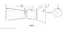
FIG. 1 shows a schematic view of the system of the present invention including a gas turbine main parts, air compressor, combustion chamber, turbine, electrical generator, and high pressure water injection system.
DETAILED DESCRIPTION OF THE DRAWINGS
FIG. 1 shows gas turbine main parts and contains, air compressor (1), combustion chamber (2), turbine #), electrical generator (4) and, the high pressure water injection system (5).
For the invention implementation, the High-pressure water injection system (5) is introduced into the gas turbine (3). At compressor (1) last stages, High-pressure injectors to be hosted between the stationary compressor blades. The high pressure nozzles are to be connected to high pressure water injection system (5). A temperature controlling device for the high pressure water being injected into the compressor (1) is essential.
DESCRIPTION OF ONE SPECIFIC EXAMPLE OR EMBODIMENT OF THE INVENTION
For a Gas turbine having the followings:
T1: Compressor-air inlet temperature ° K=283° K
T2: Compressor-air outlet temperature ° K=547° K
P2: compressor air outlet pressure=12 bar
T3: Gas turbine inlet temperature ° K=1258° K
T4: Gas turbine outlet temperature ° K=768° K
nad: adiabatic efficiency
CALCULATION
1st: improving gas turbine efficiency by reducing energy consumed by air compressor.
From steam table the following can be extracted:
Water vapor at 12 bar and compressor outlet temperature of (274° C.)=547 ° K is in the superheated zone.
Saturation Temperature=192° C.=465° K
Degree of Superheat=547−465=82 degree
Therefore compressor air outlet temperature can be reduced by 70 degrees from 547° K to 477° K without de-superheating it.
Turbine adiabatic efficiency ηad=1−(T4−T1)/(T3−T2) . . . (Brighton cycle)
The adiabatic efficiency of the gas turbine ηad=32%
Table below shows the improvement in the adiabatic efficiency from 32% to 38% in relation to drop in compressor outlet temperature from 547° K to 477° K.
| T2 ° K |
| 547 | 537 | 527 | 517 | 507 | 497 | 487 | 477 | |
| ηad % | 32 | 33 | 34 | 35 | 35 | 36 | 37 | 38 |
2nd: Improvement gas turbine overall efficiency by increasing turbine mass flow.
From gas turbine overall thermal efficiency equation where
ηt: Turbine thermal efficiency
Wt: Work done by gas turbine=(Ma+Mf) (h3−h4)
Wc: Load consumed by compressor=Ma (h2−h1)
h: air specific heat
Ma: Air mass flow rate from compressor
Mf: Fuel mass
Mw: Mass of high pressure water injected in compressor
ηt=[(Wt−Wc)/Wt]×100=1−[Ma(h2−h1)/Ma+Mw+Mf(h3−h4)]×100
From the above equation it can be seen that the increase in injected water mass (Mw) will increase gas turbine overall efficiency.
3rd: Improving gas turbine overall efficiency by maximizing turbine mass flow.
From fluid mixture equation
Taw=(MaTa+MwTw)/(Ma+Mw)
Therefore Mw=Ma(Ta−Taw)/(Taw−Tw)
Where:
Taw: Required air water mixture temperature=477° K
Ta: Compressor air outlet temperature=547° K
Tw: Injected water temperature=288° K
Mw/Ma=Water mass to air mass
Therefore the required mass of high pressure water injected to reduce compressor outlet temperature from 547° K to 477° K is Mw=0.37 Ma.
The below table shows the increase in injected water mass rate in relation to air mass flow rate corresponding to increase in injected water inlet temperature.
| Tw ° K |
| 288 | 300 | 350 | 400 | 450 | 460 | 470 | 475 | 477 | |
| Mw/ | 0.37 | 0.40 | 0.55 | 0.91 | 2.59 | 4.11 | 10 | 35 | Infinity |
| Ma | |||||||||
Claims
1-2. (canceled)
3. A process for reducing a compressor load consumption of a gas turbine comprising the steps of:
injecting a high pressure cold water into a compressor to reduce an air outlet temperature and pressure above a saturation point before leaving the compressor.
4. The process according to claim 3, further including the steps of adjusting a temperature of the high pressure cold water being injected into the compressor in order to increase the improvement in gas turbine overall efficiency.
5. A system to reduce a compressor load consumption of a gas turbine comprising:
an electric generator;
a turbine having a first end operatively connected to the electric generator;
a compressor connected to a second end of the turbine;
an injection device located between the turbine and the compressor;
wherein the injection device includes nozzles to inject a high pressure cold water into the compressor.
6. the system according to claim 5, further including a temperature controlling device connected to the injection device to control the temperature of the high pressure cold water.
Images & Drawings included:

Sources:
- United States Patent and Trademark Office - verify current appl. status at the USPTO↗
Recent applications in this class:
- » 20250243803 2025-07-31
GAS TURBINE SYSTEM, IN PARTICULAR FOR AN ELECTRICALLY DRIVEN MOTOR VEHICLE, AND MOTOR VEHICLE AND METHOD - » 20250188866 2025-06-12
STEAM INJECTED TURBINE ENGINE STEAM GENERATION CONTROL - » 20250163850 2025-05-22
TURBINE ENGINE INCLUDING A STEAM SYSTEM - » 20250084787 2025-03-13
CONDENSER FOR HYDROGEN STEAM INJECTED TURBINE ENGINE - » 20250084786 2025-03-13
PARTIAL EXHAUST CONDENSATION REGENERATOR - » 20240426242 2024-12-26
CRYOGENIC AIR SEPARATION ENHANCED GAS TURBINE - » 20240369014 2024-11-07
Aircraft powerplant with steam system and bypass - » 20240309811 2024-09-19
STEAM COOLING TURBINE ENGINE COMBUSTOR WALL - » 20240254915 2024-08-01
AUXILIARY BOILER SYSTEM FOR STEAM INJECTION CYCLE ENGINE - » 20240026817 2024-01-25
Water condition monitoring for hydrogen steam injected and inter-cooled turbine engine