Optical system and image pickup apparatus including the same
US20170108671A1
2017-04-20
15/280,550
2016-09-29
✅ Patent granted
US 10,649,184 B2
2020-05-12
-
-
Mahidere S Sahle
Canon U.S.A., Inc. IP Division
2036-09-29
Abstract:
At least one embodiment of an optical system includes, in order from an object side to an image side, a front unit having a plurality of lenses, an aperture stop, and a rear unit having a positive refractive power. In at least one embodiment, a positive lens and three or more negative lenses are disposed in the front unit, and the material of negative lenses included in the front unit, the focal length of the front unit, and the focal length of the entire optical system are set appropriately.
Assignee:
- CANON KABUSHIKI KAISHA 64,842 🇯🇵 Tokyo, Japan
Applicant:
Interested in similar patents?
Get notified when new applications in this technology area are published.
Classification:
G02B13/0045 » CPC further
Optical objectives specially designed for the purposes specified below; Miniaturised objectives for electronic devices, e.g. portable telephones, webcams, PDAs, small digital cameras characterised by the lens design having at least one aspherical surface having five or more lenses
G02B27/0025 » CPC further
Optical systems or apparatus not provided for by any of the groups - for optical correction, e.g. distorsion, aberration
G02B9/00 IPC
Optical objectives characterised both by the number of the components and their arrangements according to their sign, i.e. + or -
G02B13/04 » CPC main
Optical objectives specially designed for the purposes specified below Reversed telephoto objectives
G02B13/00 IPC
Optical objectives specially designed for the purposes specified below
G02B27/00 IPC
Optical systems or apparatus not provided for by any of the groups -
Description
BACKGROUND OF THE INVENTION
Field of the Invention
The present disclosure relates to an optical system, including a fish-eye lens, and an image pickup apparatus including the optical system, and is suitably used for, for example, an image pickup apparatus using an image pickup element, such as a digital still camera, a video camera, a monitoring camera, or a broadcasting camera, or an image pickup apparatus such as a camera using a silver-halide film.
Description of the Related Art
In recent years, image pickup apparatuses using a solid-state image pickup element, such as a monitoring camera and a video camera, have been highly functionalized and entirely reduced in size. An optical system used in these apparatuses is required to have a compact size and high optical performance. Further, the optical system is required to have a wide viewing angle to enable image taking in a wide range by a single image pickup apparatus.
A fish-eye lens is known as an optical system that allows a region having a total angle of view of about 180 degrees to be imprinted within an image circle of a specific size. Japanese Patent Laid-Open No. 2006-17837 discloses a fish-eye lens in which a positive lens and three or more negative lenses are disposed on an object side of an aperture stop to enhance optical performance.
Since the negative lenses disposed on the object side of the aperture stop have strong refractive power to widen the viewing angle in the fish-eye lens, axial chromatic aberration and lateral chromatic aberration are apt to occur. The optical system known as the fish-eye lens is required to be properly corrected for axial chromatic aberration and lateral chromatic aberration.
In the optical system disclosed in Japanese Patent Laid-Open No. 2006-17837, the material of the negative lenses disposed on the object side of the aperture stop is not properly set, and the refractive power of a front unit on the object side of the aperture stop is also not properly set. Hence, axial chromatic aberration and lateral chromatic aberration are apt to remain.
SUMMARY OF THE INVENTION
An optical system according to an aspect of the present disclosure includes, in order from an object side to an image side, a front unit including a plurality of lenses, an aperture stop, and a rear unit having a positive refractive power. The front unit includes a positive lens and three or more negative lenses. The optical system satisfies the following conditional expressions:
θgF+0.00163×νd>0.665;
νd<30.00; and
−0.30<f/ff<0.25,
where νd and θgF respectively represent an Abbe number and a partial dispersion ratio of a material of a negative lens having a smallest Abbe number among the negative lenses included in the front unit, ff represents a focal length of the front unit, and f represents a focal length of the optical system.
According to other aspects of the present disclosure, one or more additional optical systems, one or more image pickup apparatuses, and one or more methods for use with same are discussed herein. Further features of the present disclosure will become apparent from the following description of exemplary embodiments with reference to the attached drawings.
BRIEF DESCRIPTION OF THE DRAWINGS
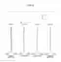
FIG. 1 is a lens sectional view of an optical system according to a first embodiment.
FIG. 2 is an aberration diagram of the optical system according to the first embodiment.
FIG. 3 is a lens sectional view of an optical system according to a second embodiment.
FIG. 4 is an aberration diagram of the optical system according to the second embodiment.
FIG. 5 is a lens sectional view of an optical system according to a third embodiment.
FIG. 6 is an aberration diagram of the optical system according to the third embodiment.
FIG. 7 is a lens sectional view of an optical system according to a fourth embodiment.
FIG. 8 is an aberration diagram of the optical system according to the fourth embodiment.
FIG. 9 is a lens sectional view of an optical system according to a fifth embodiment.
FIG. 10 is an aberration diagram of the optical system according to the fifth embodiment.
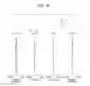
FIG. 11 is a lens sectional view of an optical system according to a sixth embodiment.
FIG. 12 is an aberration diagram of the optical system according to the sixth embodiment.
FIG. 13 is a schematic view of a principal part of at least one embodiment of an image pickup apparatus according to the present disclosure.
FIG. 14 shows characteristics of projection methods.
FIG. 15 shows the principle of correction of lateral chromatic aberration.
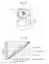
FIG. 16 shows the relationship between the Abbe number and the partial dispersion ratio of the material used for the lens.
DESCRIPTION OF THE EMBODIMENTS
At least one embodiment of an optical system and an image pickup apparatus including the optical system according to the present disclosure will be described in detail below with reference to the attached drawings. At least one embodiment of the optical system according to the present disclosure includes, in order from an object side to an image side, a front unit having a plurality of lenses, an aperture stop, and a rear unit having a positive refractive power.
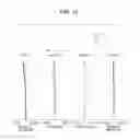
FIG. 1 is a lens sectional view of an optical system according to a first embodiment. FIG. 2 is an aberration diagram of the optical system of the first embodiment. The optical system of the first embodiment has a half angle of view of 90.20° and an F-number of about 2.00. FIG. 3 is a lens sectional view of an optical system according to a second embodiment. FIG. 4 is an aberration diagram of the optical system of the second embodiment. The optical system of the second embodiment has a half angle of view of 90.20° and an F-number of about 2.00. FIG. 5 is a lens sectional view of an optical system according to a third embodiment. FIG. 6 is an aberration diagram of the optical system of the third embodiment. The optical system of the third embodiment has a half angle of view of 100.00° and an F-number of about 2.00.
FIG. 7 is a lens sectional view of an optical system according to a fourth embodiment. FIG. 8 is an aberration diagram of the optical system of the fourth embodiment. The optical system of the fourth embodiment has a half angle of view of 93.20° and an F-number of about 2.80. FIG. 9 is a lens sectional view of an optical system according to a fifth embodiment. FIG. 10 is an aberration diagram of the optical system of the fifth embodiment. The optical system of the fifth embodiment has a half angle of view of 97.00° and an F-number of about −2.40. FIG. 11 is a lens sectional view of an optical system according to a sixth embodiment. FIG. 12 is an aberration diagram of the optical system of the sixth embodiment. The optical system of the sixth embodiment has a half angle of view of 90.20° and an F-number of about 2.00.
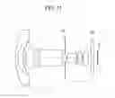
FIG. 13 is a schematic view of a principal part of at least one embodiment of a monitoring camera (image pickup apparatus) including the optical system of the present disclosure. The optical system of each of the embodiments is an image taking lens system used in an image pickup apparatus such as a digital still camera, a video camera, a monitoring camera, or a broadcasting camera. In each lens sectional view, the left side is the object side, and the right side is the image side. In each lens sectional view, Lf denotes a front unit, and Lr denotes a rear unit. SP represents an aperture stop.
GB denotes an optical block corresponding to an optical filter, a face plate, a low-pass filter, or an infrared cut-off filter, and IP represents an image plane. When at least one embodiment of the optical system of the present disclosure is used as an image pickup optical system for a video camera or a monitoring camera, the image plane IP corresponds to a solid-state image pickup element (photoelectric conversion element) such as a CCD sensor or a CMOS sensor. When at least one embodiment of the optical system of the present disclosure is used as an image pickup optical system for a silver-halide film camera, the image plane IP corresponds to a film surface.
In each spherical aberration diagram, Fno denotes the F-number and shows spherical aberrations for a g-line (wavelength 435.8 nm), an F-line (wavelength 486.1 nm), a C-line (wavelength 656.3 nm), and a d-line (wavelength 587.6 nm). In each astigmatism diagram, S denotes a sagittal image plane, and M denotes a meridional image plane. Distortion aberration is shown for the d-line. In each chromatic aberration diagram, lateral chromatic aberrations for the g-line, the F-line, the C-line, and the d-line are shown, and ω denotes the image pickup half angle of view. The distortion aberration is shown as the distortion amount in a stereographic projection method to be described later.
At least one embodiment of the optical system of the present disclosure has an angle of view of about 180°, and is intended to be mainly used as a fish-eye lens. As projection methods of the fish-eye lens, an orthogonal projection method, an equisolid angle projection method, an equidistance projection method, and a stereographic projection method are known, as described above. Here, when the image height on the projection plane is designated as Y, the focal length of the entire optical system is designated as f, and the half angle of view is designated as co, the projection methods are expressed by the following expressions:
Orthogonal projection method: Y=f×sin ω (A)
Equisolid angle projection method: Y=2f×sin(ω/2) (B)
Equidistance projection method: Y=f×ω (C)
Stereographic projection method: Y=2f×tan(ω/2) (D)
FIG. 14 schematically shows the relationship between the half angle of view and the image height when the image height at a half angle of view of 90° is 1 in the projection methods. In (A) the orthogonal projection method, an image is not so strongly compressed near the center of the image area, but is strongly compressed on the periphery of the image area. In contrast, in (D) the stereographic projection method, an image is strongly compressed near the center of the image area, but is not so strongly compressed on the periphery of the image area. In the stereographic projection method, since the degree of deformation of the image is low in the peripheral area, the influence of aberration is also conspicuous in the peripheral area. For this reason, the optical system provided for the stereographic projection method is also required to have high optical performance in the peripheral area.
A monitoring camera is also required to take a clear peripheral image, and the stereographic projection method is often used when a fish-eye lens is applied to the monitoring camera. At least one embodiment of the optical system of the present disclosure is intended to be mainly used in the fish-eye lens. To obtain high optical performance in the stereographic projection method, the optical system is required to be properly corrected for distortion aberration and spherical aberration.
In at least one embodiment of the optical system of the present disclosure, a positive lens and at least three negative lenses are disposed in the front unit Lf. To achieve wide viewing angle, an off-axis light beam needs to be greatly refracted by the negative lenses disposed on the object side in the front unit Lf. To greatly refract the light beam, it is necessary to increase the refractive power of the negative lenses. Here, when the off-axis light beam is greatly refracted by a small number of negative lenses, the refractive power of each negative lens excessively increases, and much distortion aberration, field curvature, and astigmatism occur. Further, it is difficult to correct lateral chromatic aberration and axial chromatic aberration in a well-balanced manner.
In at least one embodiment of the present disclosure, the negative refractive power is shared by at least three negative lenses disposed in the front unit Lf. This can reduce the refractive power of the negative lenses included in the front unit Lf, and can effectively suppress the occurrence of distortion aberration, field curvature, astigmatism, and so on. Further, lateral chromatic aberration and axial chromatic aberration can be corrected in a well-balanced manner.
The optical system of each of the embodiments satisfies the following conditional Expressions:
θgF+0.00163×νd>0.665 (1)
νd<30.00 (2)
−0.30<f/ff<0.25 (3).
where νd represents the Abbe number of the material of a negative lens Gn having the smallest Abbe number among the negative lenses included in the front unit Lf, θgF represents the partial dispersion ratio, ff represents the focal length of the front unit Lf, and f represents the focal length of the entire optical system.
Here, the Abbe number νd and the partial dispersion ratio θgF are values expressed as follows:
νd=(Nd−1)/(NF−NC)
θgF=(Ng−Nf)/(NF−NC).
where Ng, NF, NC and Nd respectively denote the refractive indices of the material for the g-line (wavelength 435.8 nm), the F-line (wavelength 486.1 nm), the C-line (wavelength 656.3 nm), and the d-line (wavelength 587.6 nm).
The principle of correction of lateral chromatic aberration will be described with reference to FIG. 15. In at least one embodiment of the optical system of the present disclosure, lateral chromatic aberration is corrected by using a material having a high dispersion (low Abbe number) and a high anomalous dispersion for the negative lenses included in the front unit Lf. FIG. 15 schematically illustrates the optical path in an optical system having a negative lens included in the front unit Lf and having a high dispersion and a high anomalous dispersion, an aperture stop, and a rear unit having a positive refractive power.
In general, in a superwide-angle lens of a retrofocus type, such as a fish-eye lens, an image is formed in an area where the image height on the image plane is large and at a position where the g-line is located far from the optical axis than the d-line. As illustrated in FIG. 15, the image forming position at the g-line can be shifted closer to the optical axis by using the material having a high dispersion and a high anomalous dispersion for the negative lens included in the front unit Lf. Thus, lateral chromatic aberration at the g-line can be properly corrected.
FIG. 16 shows the distribution of materials used for the lens. In FIG. 16, the vertical line shows a partial dispersion ratio θgF, and the horizontal axis shows an Abbe number νd. A straight line shown by a broken line is a normal line. Most materials used for the lens are distributed near the normal line. Materials distributed at positions located far from the normal line have an anomalous dispersion. As shown in FIG. 16, the materials having an anomalous dispersion are concentrated in a low-dispersion region and a high-dispersion region.
It is not preferable to use a material that does not satisfy Conditional Expressions (1) and (2) as the material of the negative lens Gn because it is difficult to properly correct lateral chromatic aberration.
Conditional Expression (3) defines the ratio of the focal length ff of the front unit Lf and the focal length f of the entire optical system. When the value is smaller than the lower limit value of Conditional Expression (3), the negative refractive power of the front unit Lf becomes too strong, and the diverging effect of the marginal ray near the aperture stop is too large. As a result, it is necessary to increase the refractive power of the positive lens disposed in the rear unit Lr near the aperture stop, and this makes it difficult to properly correct spherical aberration occurring in the rear unit Lr. Further, if the positive refractive power is dispersed by increasing the number of positive lenses included in the rear unit Lr in order to correct spherical aberration, the number of lenses increases, and this increases the total size of the optical system.
When the value is larger than the upper limit value of Conditional Expression (3), the positive refractive power of the front unit Lf becomes too strong, and the converging effect of the marginal ray near the aperture stop becomes too large. As a result, the height of a light beam entering the rear unit Lr becomes too small, and it is difficult to properly correct aberration, such as axial chromatic aberration, occurring in the front unit Lf.
In each embodiment, the elements are appropriately set to satisfy Conditional Expressions (1) to (3), as described above. Thus, it is possible to obtain a compact and wide-angle zoom lens having high optical performance.
In each embodiment, the numerical ranges of Conditional Expressions (1) to (3) are preferably set as follows:
θgF+0.00163×νd>0.675 (1a)
νd<25.00 (2a)
−0.25<f/ff<0.22 (3a).
The numerical ranges of Conditional Expressions (1) to (3) are more preferably set as follows:
θgF+0.00163×νd>0.685 (1b)
νd<20.00 (2b)
−0.20<f/ff<0.20 (3b).
Further, in each embodiment, at least one of the following conditional expressions is preferably satisfied:
−25.00<fn/f<−2.00 (4)
1.20<(GnR1+GnR2)/(GnR1−GnR2)<8.00 (5)
1.20<νna/νpa<5.00 (6)
0.00≦|(R1+R2)|/(R1−R2)1.00 (7)
7.00<TD/f<45.00 (8).
Here, fn represents the focal length of the negative lens Gn, GnR1 represents the curvature radius of an object-side lens surface of the negative lens Gn, and GnR2 represents the curvature radius of an image-side lens surface of the negative lens Gn. Further, νna represents the average value of the Abbe numbers of the materials of all negative lenses included in the front unit Lr, and νpa represents the average value of the Abbe numbers of the materials of all positive lenses included in the front unit Lf. Still further, R1 represents the curvature radius of a lens surface of the rear unit Lr closest to the object side, R2 represents the curvature radius of a lens surface of the rear unit Lr closest to the image side, and TD represents the distance on the optical axis from a lens surface of the front unit Lf closest to the object side to the lens surface of the rear unit Lr closest to the image side.
Conditional Expression (4) defines the ratio of the focal length fn of the negative lens Gn and the focal length f of the entire optical system. When the value is smaller than the lower limit value of Conditional Expression (4), the refractive power of the negative lens Gn becomes too weak. As a result, it is difficult to properly correct lateral chromatic aberration. When the value is larger than the upper limit value of Conditional Expression (4), the refractive power of the negative lens Gn becomes too strong. As a result, it is difficult to properly correct distortion aberration, curvature of field, and astigmatism, and much axial chromatic aberration occurs.
Conditional Expression (5) defines the shape of the negative lens Gn. Conditional Expression (5) shows that the negative lens Gn has a meniscus shape that is convex to the object side. When the value is smaller than the lower limit value of Conditional Expression (5), the curvature radius of the object-side lens surface of the negative lens Gn becomes too large. As a result, the refracting angle of the light beam that forms an image at the peripheral image height becomes too large, and much distortion aberration, field curvature, and astigmatism occur. When the value is larger than the upper limit value of Conditional Expression (5), the curvature radius of the object-side lens surface of the negative lens Gn is too close to the curvature radius of the image-side lens surface. As a result, the negative refractive power of the negative lens Gn becomes too weak, and it is difficult to achieve a sufficiently wide viewing angle.
Conditional Expression (6) defines the ratio of the average value νna of the Abbe numbers of the materials of all negative lenses included in the front unit Lf and the average value νpa of the Abbe numbers of the materials of all positive lenses included in the front unit Lf. When the value is larger than the upper limit value or smaller than the lower limit value of Conditional Expression 6, the achromatic effect of the C-line and the F-line in the front unit Lf decreases, and it is difficult to properly correct chromatic aberration.
Conditional Expression (7) defines the curvature radius R1 of the lens surface of the rear unit Lr closest to the object side and the curvature radius R2 of the lens surface of the rear unit Lr closest to the image side. Conditional Expression (7) shows that both the lens surface of the rear unit Lr closest to the object side and the lens surface of the rear unit Lr closest to the image side are convex surfaces. By forming the lens surface of the rear unit Lr closest to the object side by a convex surface, the height of the on-axis marginal ray passing through the rear unit Lr can be decreased. Thus, it is possible to shorten the effective diameter of the lenses included in the rear unit Lr and, as a result, to reduce the total size of the lens system.
By forming the lens surface of the rear unit Lr closest to the image side by a convex surface, telecentricity can be enhanced. When at least one embodiment of the optical system of the present disclosure is used in an image pickup apparatus including an image pickup element, it is preferable that a light beam should enter a light-receiving surface of the image pickup element from the perpendicular direction. If the incident angle of the light beam on the light-receiving surface increases, the light quantity decreases particularly at the peripheral image height, and the peripheral light quantity ratio becomes too low. In at least one embodiment of the present disclosure, the decrease in peripheral light quantity ratio is prevented by forming the lens surface of the rear unit Lr closest to the image side by a convex surface to enhance telecentricity. When the value is larger than the upper limit value or smaller than the lower limit value of Conditional Expression (7), it is difficult to suppress the decrease in peripheral light quantity ratio while achieving size reduction of the entire lens system.
Conditional Expression (8) defines the ratio of the overall lens length TD of the entire optical system and the focal length f of the entire optical system. To shorten the overall lens length TD to be smaller than the lower limit value of Conditional Expression (8), it is necessary to increase the refractive powers of the lens surfaces. When the refractive powers of the lens surfaces are increased, various aberrations occur, and this deteriorates optical performance of the optical system. When the overall lens length TD increases to be larger than the upper limit value of Conditional Expression (8), the total size of the optical system is increased.
The numeral ranges of Conditional Expressions (4) to (8) are preferably set as follows:
−20.00<fn/f<−3.00 (4a)
1.50<(GnR1+GnR2)/(GnR1−GnR2)<7.00 (5a)
1.30<νna/νpa<4.00 (6a)
0.03≦|(R1+R2)|/(R1−R2)0.80 (7a)
10.00<TD/f<40.00 (8a).
The numeral ranges of Conditional Expressions (4) to (8) are more preferably set as follows:
−15.00<fn/f<−4.00 (4b)
2.00<(GnR1+GnR2)/(GnR1−GnR2)<6.00 (5b)
1.40<νna/νpa<3.00 (6b)
0.05≦|(R1+R2)|/(R1−R2)0.75 (7b)
12.00<TD/f<35.00 (8b).
The front unit Lf is preferably composed of seven or less lenses. In each embodiment, the optical system has an angle of view of about 180°, the effective diameter of each lens included in the front unit Lf is apt to be large, and the weight of each lens is also apt to be large. By composing the front unit Lf of seven or less lenses, the total weight of the front unit Lf can be effectively reduced. The rear unit Lr is preferably composed of five or less lenses. This can effectively achieve size reduction and weight reduction of the entire lens system.
In each embodiment, at least two aspherical lenses are preferably disposed in the optical system. By properly using the aspherical lenses, field curvature, astigmatism, and spherical aberration can be corrected well. In particular, an aspherical lens that is convex to the image side is preferably disposed on a side of the rear unit Lr closest to the image side. This can make the incident light angle on the image pickup element close to a telecentric condition, and can suppress the decrease in peripheral light quantity ratio.
When at least one embodiment of the optical system of the present disclosure is applied to an image pickup apparatus including an image pickup element that receives an image formed by the optical system, the following conditional expressions are preferably satisfied:
85°<ωmax<120° (9)
1.55<Y80/f<1.80 (10)
0.20<f2/(Y80×Fno)<2.50 (11).
Here, ωmax represents the maximum half angle of view, Y80 represents the image height on the image pickup element at an angle of view of 80°, f represents the focal length of the entire optical system, and Fno represents the full aperture F-number of the optical system at infinity.
When the maximum half angle of view ωmax decreases to be smaller than the lower limit value of Conditional Expression (9), a sufficiently wide viewing angle cannot be achieved. When the maximum half angle of view ωmax increases to be larger than the upper limit value of Conditional Expression (9), the amount of information at each angle of view decreases, and this deteriorates resolution.
Conditional Expression (10) defines the shift of the image height at which a light beam having a half angle of view of 80° forms an image. In the stereographic projection method, the image height is determined by the focal length and the half angle of view, as described above. Here, when an image of a subject is formed on an imaging surface via the optical system in the stereographic projection method, distortion aberration occurs, and the image height shifts. When the value is smaller than the lower limit value of Conditional Expression (10), the image height at which the light beam having the half angle of view of 80° forms an image is too lower than the ideal image height, and information near the optical axis is excessively compressed. This may deteriorate image quality. When the value is larger than the upper limit value of Conditional Expression (10), the image height at which the light beam having the half angle of view of 80° forms an image is too higher than the ideal image height, and information in the peripheral area is excessively compressed. This may deteriorate image quality.
Conditional Expression (11) defines the hyperfocal distance of a pan-focus optical system. In the pan-focus optical system, all subject distances in a range from half the hyperfocal distance to infinity are within the depth of field. The closest in-focus distance is ½ of a hyperfocal distance sh. Here, the hyperfocal distance sh is expressed by sh=f2/(ε×Fno) where ε represents the diameter of the permissible circle of confusion. The diameter ε of the permissible circle of confusion is proportional to a pixel pitch p, and is expressed by ε∝p. Further, when pixels are uniformly arranged in the image pickup element, since the pixel pitch p is proportional to the image height Y, the hyperfocal distance sh is proportional to f2/(Y×Fno).
When the value is smaller than the lower limit value of Conditional Expression (11), the full aperture F-number Fno at infinity becomes too large, and it is difficult to ensure sufficient brightness. Moreover, the focal length f of the entire optical system becomes too short, and much aberration occurs. When the value is larger than the upper limit value of Conditional Expression (11), the closest in-focus distance increases, and the image taking area is narrowed.
In each embodiment, numerical ranges of Conditional Expressions (9) to (11) are preferably set as follows:
87°<ωmax<115° (9a)
1.59<Y80/f<1.77 (10a)
0.25<f2/(Y80×Fno)<2.00 (11a).
The numerical ranges of Conditional Expressions (9) to (11) are more preferably set as follows:
89°<ωmax<110° (9b)
1.63<Y80/f<1.73 (10b)
0.30<f2/(Y80×Fno)<1.50 (11b).
Next, the lens configurations in the embodiments will be described. In the optical systems of the first embodiment and the second embodiment, the front unit Lf consists of three negative lenses each having a meniscus shape that is convex to the object side and a cemented lens of a biconcave negative lens and a biconvex positive lens, which are arranged in order from the object side to the image side. By forming both surfaces of the third negative lens from the object side by aspherical surfaces, field curvature is corrected well. The second negative lens from the object side corresponds to the negative lens Gn having the smallest Abbe number among the negative lenses included in the front unit Lf.
The rear unit Lr consists of a biconvex positive lens, a cemented lens of a biconcave negative lens and a biconvex positive lens, and a biconvex positive lens, which are arranged in order from the object side to the image side. By forming both surfaces of the positive lens closest to the image side by aspherical surfaces, field curvature and spherical aberration are corrected well.
In the optical system of the third embodiment, the front unit Lf consists of three negative lenses each having a meniscus shape that is convex to the object side, a biconcave negative lens, and a cemented lens of a meniscus negative lens that is convex to the object side and a biconvex positive lens, which are arranged in order from the object side to the image side. By forming both surfaces of the third negative lens from the object side by aspherical surfaces, field curvature is corrected well. The fifth negative lens from the object side corresponds to the negative lens Gn. The rear unit Lr consists of a biconvex positive lens, a cemented lens of a biconvex positive lens and a biconcave negative lens, and a biconvex positive lens, which are arranged in order from the object side to the image side. By forming both surfaces of the positive lens in the rear unit Lr closest to the object side and both surfaces of the positive lens in the rear unit Lr closest to the image side by aspherical surfaces, field curvature and spherical aberration are corrected well.
In the optical system of the fourth embodiment, the configuration of the front unit Lf is the same as that of the third embodiment. The rear unit Lr consists of a biconvex positive lens, a cemented lens of a meniscus positive lens that is convex to the image side and a biconcave negative lens, a biconvex positive lens, and a biconvex positive lens, which are arranged in order from the object side to the image side. By forming both surfaces of the positive lens closest to the object side and both surfaces of the positive lens closest to the image side by aspherical surfaces, field curvature and spherical aberration are corrected well. In the optical system according to the fifth embodiment, configurations of the front unit Lf and the rear unit Lr are the same as those adopted in the third embodiment.
In the optical system according to the sixth embodiment, the front unit Lf consists of two meniscus negative lenses each of which is convex to the object side, a biconcave negative lens, and a biconvex positive lens, which are arranged in order from the object side to the image side. By forming both surfaces of the third negative lens from the object side by aspherical surfaces, field curvature is corrected well. The second negative lens from the object side corresponds to the negative lens Gn. The configuration of the rear unit Lr is the same as that adopted in the first and second embodiments.
Next, lens data in first to sixth numerical embodiments corresponding to the first to sixth embodiments of the present disclosure will be shown. In each numerical embodiment, i represents the order of an optical surface from the object side, ri represents the curvature radius of the i-th optical surface (i-th surface), di represents the distance between the i-th surface and the (i+1)-th surface, and ndi and νdi represent the refractive index and Abbe number, respectively, of the material of the i-th optical member for the d-line.
When K represents the eccentricity, A4, A6, A8, and A10 each represent the aspherical surface coefficient, and x represents the displacement amount from the surface vertex in the optical-axis direction at a height h from the optical axis, the aspherical surface shape is expressed by the following expression:
x=(h2/r)/[1+[1−(1+K)(h/r)2]1/2]+A4h4+A6h6+A8h8+A10h10
where r represents the paraxial curvature radius. Further, |e−Z| means |10−Z|. In each embodiment, the partial dispersion ratio θgF and the focal length fn of the lens corresponding to the negative lens Gn are also shown.
In each embodiment, the back focus (BF) refers to the distance from the surface of the lens system closest to the image side to the image plane expressed by the equivalent air length. Table shows the correspondences of the numerical embodiments to the above-described conditional expressions.
First Numerical Embodiment
| Unit mm |
| Surface data |
| Surface number | r | d | nd | νd | θgF | fn |
| 1 | 24.640 | 1.25 | 1.77250 | 49.6 | ||
| 2 | 10.334 | 3.08 | ||||
| 3 | 13.519 | 1.00 | 1.95906 | 17.5 | 0.6598 | −16.79 |
| 4 | 7.083 | 4.69 | ||||
| 5* | 8.181 | 1.00 | 1.76802 | 49.2 | ||
| 6* | 3.330 | 3.00 | ||||
| 7 | −13.041 | 0.60 | 1.59522 | 67.7 | ||
| 8 | 8.521 | 6.87 | 2.00069 | 25.5 | ||
| 9 | −15.485 | 1.65 | ||||
| 10 (Stop) | ∞ | 1.10 | ||||
| 11 | 5.634 | 4.46 | 1.49700 | 81.5 | ||
| 12 | −5.636 | 0.51 | ||||
| 13 | −4.287 | 0.40 | 1.85478 | 24.8 | ||
| 14 | 10.208 | 2.72 | 1.49700 | 81.5 | ||
| 15 | −6.064 | 0.33 | ||||
| 16* | 9.089 | 3.52 | 1.55332 | 71.7 | ||
| 17* | −7.138 | 1.46 | ||||
| 18 | ∞ | 1.60 | 1.51630 | 64.1 | ||
| 19 | ∞ | 2.00 | ||||
| Image plane | ∞ | |||||
| Aspherical surface data |
| Fifth surface |
| K = −1.74182e+000 | A 6 = −5.36705e−005 | A 8 = 1.23192e−006 |
| A 10 = −3.06369e−009 |
| Sixth surface |
| K = −1.16929e+000 | A 4 = 1.39638e−003 | A 6 = −1.20156e−004 |
| A 8 = −1.51135e−006 | A 10 = 2.35477e−007 |
| Sixteenth surface |
| K = −1.89973e+000 | A 4 = −6.45750e−004 | A 6 = 2.02657e−005 |
| A 8 = −1.14090e−006 | A 10 = 1.46887e−008 |
| Seventeenth surface |
| K = −7.98305e−001 | A 4 = 7.08293e−004 | A 6 = −1.49882e−005 |
| Various data |
| Focal length | 2.00 |
| F-number | 2.00 |
| Half angle of view | 90.20 |
| Image height | 4.00 |
| Overall lens length | 36.18 |
| BF | 4.51 |
| Lens unit data |
| Unit | Starting surface | Focal length |
| Front unit | 1 | −15.00 |
| Rear unit | 11 | 8.00 |
Second Numerical Embodiment
| Unit mm |
| Surface data |
| Surface number | r | d | nd | νd | θgF | fn |
| 1 | 25.739 | 1.25 | 1.77250 | 49.6 | ||
| 2 | 11.637 | 3.01 | ||||
| 3 | 14.589 | 1.00 | 1.95906 | 17.5 | 0.6598 | −23.55 |
| 4 | 8.566 | 4.89 | ||||
| 5* | 8.545 | 1.00 | 1.76802 | 49.2 | ||
| 6* | 3.330 | 5.07 | ||||
| 7 | −8.737 | 0.60 | 1.59522 | 67.7 | ||
| 8 | 10.806 | 5.67 | 2.00069 | 25.5 | ||
| 9 | −14.548 | 1.87 | ||||
| 10 (Stop) | ∞ | 1.10 | ||||
| 11 | 5.558 | 4.86 | 1.49700 | 81.5 | ||
| 12 | −5.560 | 0.54 | ||||
| 13 | −4.083 | 0.40 | 1.85478 | 24.8 | ||
| 14 | 11.045 | 2.71 | 1.49700 | 81.5 | ||
| 15 | −6.148 | 1.24 | ||||
| 16* | 9.090 | 3.98 | 1.55332 | 71.7 | ||
| 17* | −7.140 | 1.46 | ||||
| 18 | ∞ | 1.60 | 1.51630 | 64.1 | ||
| 19 | ∞ | 2.00 | ||||
| Image plane | ∞ | |||||
| Aspherical surface data |
| Fifth surface |
| K = 3.37697e−001 | A 6 = −6.93664e−005 | A 8 = 1.99836e−006 |
| A 10 = −2.02822e−008 |
| Sixth surface |
| K = −1.03997e+000 | A 4 = 1.46726e−003 | A 6 = −9.52085e−005 |
| A 8 = −1.69641e−006 | A 10 = 2.26511e−007 |
| Sixteenth surface |
| K = −1.06802e+000 | A 4 = −7.50562e−004 | A 6 = 2.07296e−005 |
| A 8 = −1.04976e−006 | A 10 = 1.28819e−008 |
| Seventeenth surface |
| K = −6.65735e−001 | A 4 = 6.16060e−004 | A 6 = −1.49996e−005 |
| Various data |
| Focal length | 2.00 |
| F-number | 2.00 |
| Half angle of view | 90.20 |
| Image height | 4.00 |
| Overall lens length | 39.19 |
| BF | 4.51 |
| Lens unit data |
| Unit | Starting surface | Focal length |
| Front unit | 1 | −12.00 |
| Rear unit | 11 | 8.97 |
Third Numerical Embodiment
| Unit mm |
| Surface data |
| Surface number | r | d | nd | νd | θgF | fn |
| 1 | 25.195 | 1.20 | 1.80400 | 46.6 | ||
| 2 | 11.653 | 5.00 | ||||
| 3 | 14.557 | 0.70 | 2.00100 | 29.1 | ||
| 4 | 6.859 | 4.19 | ||||
| 5* | 20.501 | 0.50 | 1.80610 | 40.7 | ||
| 6* | 5.716 | 3.99 | ||||
| 7 | −73.177 | 0.45 | 1.59522 | 67.7 | ||
| 8 | 9.142 | 0.86 | ||||
| 9 | 13.936 | 0.45 | 2.10205 | 16.8 | 0.6721 | −15.13 |
| 10 | 7.462 | 10.57 | 2.00069 | 25.5 | ||
| 11 | −13.962 | 4.64 | ||||
| 12 (Stop) | ∞ | 2.56 | ||||
| 13* | 6.320 | 1.94 | 1.49710 | 81.6 | ||
| 14* | −17.197 | 0.09 | ||||
| 15 | 66.768 | 1.39 | 1.49700 | 81.5 | ||
| 16 | −5.178 | 0.45 | 1.84666 | 23.8 | ||
| 17 | 16.143 | 2.64 | ||||
| 18* | 13.935 | 3.54 | 1.55332 | 71.7 | ||
| 19* | −5.438 | 1.20 | ||||
| 20 | ∞ | 1.50 | 1.51630 | 64.1 | ||
| 21 | ∞ | 2.24 | ||||
| Image plane | ∞ | |||||
| Aspherical surface data |
| Fifth surface |
| K = 2.00114e+000 | A 4 = −1.01987e−004 | A 6 = −5.72800e−006 |
| A 8 = −7.90180e−008 | A 10 = 2.62920e−009 |
| Sixth surface |
| K = −7.26641e−002 | A 4 = −3.63561e−004 | A 6 = −2.44288e−005 |
| A 8 = −2.31468e−007 | A 10 = −2.01264e−009 |
| Thirteenth surface |
| K = −3.51840e+000 | A 4 = 2.29819e−003 | A 6 = 3.07570e−004 |
| A 8 = −3.86576e−005 | A 10 = 3.46968e−006 |
| Fourteenth surface |
| K = 4.84763e+000 | A 4 = 1.34834e−003 | A 6 = 2.43191e−004 |
| Eighteenth surface |
| K = −3.04798e+000 | A 4 = −6.21861e−004 | A 6 = 2.90573e−005 |
| A 8 = 1.09122e−006 | A 10 = −4.37169e−008 |
| Nineteenth surface |
| K = −3.38885e+000 | A 4 = −1.03947e−003 | A 6 = 4.88982e−005 |
| A 8 = 2.37243e−007 | ||
| Various data |
| Focal length | 2.00 |
| F-number | 2.00 |
| Half angle of view | 100.00 |
| Image height | 4.76 |
| Overall lens length | 45.16 |
| BF | 4.43 |
| Lens unit data |
| Unit | Starting surface | Focal length |
| Front unit | 1 | 15.03 |
| Rear unit | 13 | 9.14 |
Fourth Numerical Embodiment
| Unit mm |
| Surface data |
| Surface number | r | d | nd | νd | θgF | fn |
| 1 | 30.469 | 1.20 | 1.83481 | 42.7 | ||
| 2 | 9.786 | 5.68 | ||||
| 3* | 24.865 | 0.70 | 1.88202 | 37.2 | ||
| 4* | 7.378 | 4.35 | ||||
| 5 | 80.368 | 0.50 | 1.80400 | 46.6 | ||
| 6 | 11.041 | 6.90 | ||||
| 7 | −27.683 | 0.45 | 1.71300 | 53.9 | ||
| 8 | 13.140 | 0.63 | ||||
| 9 | 16.036 | 0.45 | 1.95906 | 17.5 | 0.6598 | −28.20 |
| 10 | 9.928 | 3.91 | 2.00069 | 25.5 | ||
| 11 | −16.600 | 10.80 | ||||
| 12 (Stop) | ∞ | 0.47 | ||||
| 13* | 20.010 | 1.14 | 1.49710 | 81.6 | ||
| 14* | −20.005 | 0.50 | ||||
| 15 | −14.518 | 1.06 | 1.48749 | 70.2 | ||
| 16 | −4.427 | 0.45 | 2.00100 | 29.1 | ||
| 17 | 85.011 | 0.55 | ||||
| 18 | 14.918 | 2.34 | 1.49700 | 81.5 | ||
| 19 | −75.490 | 0.59 | ||||
| 20* | 14.013 | 2.34 | 1.55332 | 71.7 | ||
| 21* | −4.798 | 9.98 | ||||
| Image plane | ∞ | |||||
| Aspherical surface data |
| Third surface |
| K = 9.26595e−001 | A 4 = 1.74251e−004 | A 6 = −9.19603e−008 |
| A 8 = −6.18843e−009 |
| Fourth surface |
| K = −1.55179e+000 | A 4 = 3.15057e−004 | A 6 = 6.87929e−006 |
| Thirteenth surface |
| K = 1.16740e+000 | A 4 = 1.89852e−004 | A 6 = 4.36520e−004 |
| A 8 = −2.12647e−005 | A 10 = 8.21093e−007 |
| Fourteenth surface |
| K = −2.35943e+000 | A 4 = 6.47874e−004 | A 6 = 5.69574e−004 |
| Twentieth surface |
| K = −1.60281e+000 | A 4 = −1.12845e−003 | A 6 = 6.14929e-006 |
| A 8 = 8.93187e−007 | A 10 = −4.26931e−008 |
| Twenty-first surface |
| K = −1.83970e+000 | A 4 = −1.11349e−003 | A 6 = −9.48115e-006 |
| A 8 = 2.37243e−007 | ||
| Various data |
| Focal length | 1.50 |
| F-number | 2.80 |
| Half angle of view | 93.20 |
| Image height | 3.15 |
| Overall lens length | 55.00 |
| BF | 9.98 |
| Lens unit data |
| Unit | Starting surface | Focal length |
| Front unit | 1 | −78.27 |
| Rear unit | 13 | 8.24 |
Fifth Numerical Embodiment
| Unit mm |
| Surface data |
| Surface number | r | d | nd | νd | θgF | fn |
| 1 | 25.144 | 1.20 | 1.80400 | 46.6 | ||
| 2 | 11.653 | 5.21 | ||||
| 3 | 13.855 | 0.70 | 1.91082 | 35.3 | ||
| 4 | 6.859 | 4.19 | ||||
| 5 | 73.515 | 0.50 | 1.73800 | 32.3 | ||
| 6 | 5.907 | 2.74 | ||||
| 7 | −19.819 | 0.45 | 1.59522 | 67.7 | ||
| 8 | 9.142 | 1.38 | ||||
| 9 | 14.767 | 0.45 | 1.95906 | 17.5 | 0.6598 | −16.22 |
| 10 | 7.462 | 4.52 | 2.00069 | 25.5 | ||
| 11 | −13.220 | 6.79 | ||||
| 12 (Stop) | ∞ | 1.40 | ||||
| 13* | 6.320 | 1.45 | 1.49710 | 81.6 | ||
| 14* | −13.855 | 0.10 | ||||
| 15 | 66.768 | 1.14 | 1.48749 | 70.2 | ||
| 16 | −5.178 | 0.45 | 1.85478 | 24.8 | ||
| 17 | 23.099 | 3.69 | ||||
| 18* | 13.935 | 3.98 | 1.55332 | 71.7 | ||
| 19* | −4.756 | 1.20 | ||||
| 20 | ∞ | 1.50 | 1.51630 | 64.1 | ||
| 21 | ∞ | 2.28 | ||||
| Image plane | ∞ | |||||
| Aspherical surface data |
| Thirteenth surface |
| K = −4.32378e−001 | A 4 = 2.29819e−003 | A 6 = 3.07570e−004 |
| A 8 = 4.46609e−005 | A 10 = −7.05731e−006 | |
| −7.05731e−006 |
| Fourteenth surface |
| K = 2.72506e+000 | A 4 = 3.06342e−003 | A 6 = 5.10637e−004 |
| Eighteenth surface |
| K = −3.04798e+000 | A 4 = −6.21861e−004 | A 6 = 2.90573e−005 |
| A 8 = 1.09122e−006 | A 10 = −3.89032e−008 |
| Nineteenth surface |
| K = −3.38885e+000 | A 4 = −1.43938e−003 | A 6 = 5.31066e−005 |
| A 8 = 2.37243e−007 | ||
| Various data |
| Focal length | 2.02 |
| F-number | 2.40 |
| Half angle of view | 97.00 |
| Image height | 4.36 |
| Overall lens length | 40.34 |
| BF | 2.28 |
| Lens unit data |
| Unit | Starting surface | Focal length |
| Front unit | 1 | 471.79 |
| Rear unit | 13 | 8.23 |
Sixth Numerical Embodiment
| Unit mm |
| Surface data |
| Surface number | r | d | nd | νd | θgF | fn |
| 1 | 32.507 | 1.25 | 1.48749 | 70.2 | ||
| 2 | 10.511 | 3.06 | ||||
| 3 | 15.428 | 1.00 | 1.95906 | 17.5 | 0.6598 | −15.37 |
| 4 | 7.299 | 5.53 | ||||
| 5* | −30.857 | 1.00 | 1.72903 | 54.0 | ||
| 6* | 3.923 | 1.59 | ||||
| 7 | 9.089 | 13.77 | 2.00069 | 25.5 | ||
| 8 | −30.300 | 1.45 | ||||
| 9 (Stop) | ∞ | 1.10 | ||||
| 10 | 6.330 | 5.69 | 1.49700 | 81.5 | ||
| 11 | −6.332 | 0.41 | ||||
| 12 | −4.591 | 0.40 | 1.85478 | 24.8 | ||
| 13 | 37.865 | 2.66 | 1.49700 | 81.5 | ||
| 14 | −6.205 | 0.30 | ||||
| 15* | 10.007 | 3.12 | 1.55332 | 71.7 | ||
| 16* | −7.135 | 1.46 | ||||
| 17 | ∞ | 1.60 | 1.51630 | 64.1 | ||
| 18 | ∞ | 2.00 | ||||
| Image plane | ∞ | |||||
| Aspherical surface data |
| Fifth surface |
| K = 3.99706e+000 | A 6 = 7.54242e−007 | A 8 = −4.06321e−007 |
| A 10 = 9.99311e−009 |
| Sixth surface |
| K = −3.19199e+000 | A 4 = 2.82797e−003 | A 6 = −9.13900e−005 |
| A 8 = −4.23232e−007 | A 10 = 7.13283e−008 |
| Fifteenth surface |
| K = 1.04119e+000 | A 4 = −1.28724e−003 | A 6 = 5.41024e−005 |
| A 8 = −3.15358e−006 | A 10 = 4.81716e−008 |
| Sixteenth surface |
| K = 5.22651e−002 | A 4 = 1.16275e−003 | A 6 = −1.42289e−005 |
| Various data |
| Focal length | 2.00 |
| F-number | 2.00 |
| Half angle of view | 90.20 |
| Image height | 4.00 |
| Overall lens length | 42.33 |
| BF | 4.51 |
| Lens unit data |
| Unit | Starting surface | Focal length |
| Front unit | 1 | −15.00 |
| Rear unit | 10 | 8.00 |
| TABLE | ||||||
| First | Second | Third | Fourth | Fifth | Sixth | |
| Embodiment | Embodiment | Embodiment | Embodiment | Embodiment | Embodiment | |
| Conditional | 0.688 | 0.688 | 0.699 | 0.688 | 0.688 | 0.688 |
| Expression | ||||||
| (1) | ||||||
| Conditional | 17.5 | 17.5 | 16.8 | 17.5 | 17.5 | 17.5 |
| Expression | ||||||
| (2) | ||||||
| Conditional | −0.13 | −0.17 | 0.13 | −0.07 | 0.004 | −0.13 |
| Expression | ||||||
| (3) | ||||||
| Conditional | −8.39 | −11.77 | −7.56 | −4.70 | −8.03 | −7.68 |
| Expression | ||||||
| (4) | ||||||
| Conditional | 3.20 | 3.84 | 3.31 | 4.25 | 3.04 | 2.80 |
| Expression | ||||||
| (5) | ||||||
| Conditional | 1.80 | 1.80 | 1.80 | 1.77 | 1.78 | 1.86 |
| Expression | ||||||
| (6) | ||||||
| Conditional | 0.12 | 0.12 | 0.08 | 0.15 | 0.14 | 0.06 |
| Expression | ||||||
| (7) | ||||||
| Conditional | 18.09 | 19.59 | 22.57 | 28.38 | 19.98 | 21.16 |
| Expression | ||||||
| (8) | ||||||
| Conditional | 90.20 | 90.20 | 100.00 | 91.60 | 97.00 | 90.20 |
| Expression | ||||||
| (9) | ||||||
| Conditional | 1.70 | 1.70 | 1.69 | 1.69 | 1.67 | 1.72 |
| Expression | ||||||
| (10) | ||||||
| Conditional | 0.59 | 0.59 | 0.59 | 1.27 | 0.50 | 0.58 |
| Expression | ||||||
| (11) | ||||||
Next, an embodiment of a monitoring camera (image pickup apparatus) using at least one embodiment of the optical system of the present disclosure as an image pickup optical system will be described with reference to FIG. 13. In FIG. 13, reference numeral 20 denotes a monitoring camera body. An image-taking optical system 21 is configured by any of the optical systems according to the above-described first to sixth embodiments. A solid-state image pickup element 22 (photoelectric conversion element), such as a CCD sensor or a CMOS sensor, is built in the monitoring camera body 20 and receives a subject image formed by the image-taking optical system 21.
By thus applying at least one embodiment of the optical system of the present disclosure to the image pickup apparatus such as the monitoring camera, a compact and wide-angle image pickup apparatus having high optical performance can be obtained.
While the present disclosure has been described with reference to exemplary embodiments, it is to be understood that the disclosure is not limited to the disclosed exemplary embodiments. The scope of the following claims is to be accorded the broadest interpretation so as to encompass all such modifications and equivalent structures and functions.
This application claims the benefit of Japanese Patent Application No. 2015-203191, filed Oct. 14, 2015, which is hereby incorporated by reference herein in its entirety.
Claims
What is claimed is:1. An optical system comprising in order from an object side to an image side:
a front unit including a plurality of lenses;
an aperture stop; and
a rear unit having a positive refractive power,
wherein the front unit includes a positive lens and three or more negative lenses, and
wherein the optical system satisfies the following conditional expressions:
θgF+0.00163×νd>0.665,
νd<30.00, and
−0.30<f/ff<0.25,
where νd and θgF respectively represent an Abbe number and a partial dispersion ratio of a material of a negative lens having a smallest Abbe number among the negative lenses included in the front unit, ff represents a focal length of the front unit, and f represents a focal length of the optical system.
2. The optical system according to claim 1, wherein the following conditional expression is satisfied:
−25.00<fn/f<−2.00,
where fn represents a focal length of the negative lens.
3. The optical system according to claim 1, wherein the following conditional expression is satisfied:
1.20<(GnR1+GnR2)/(GnR1−GnR2)<8.00,
where GnR1 represents a curvature radius of an object-side lens surface of the negative lens, and GnR2 represents a curvature radius of an image-side lens surface of the negative lens.
4. The optical system according to claim 1, wherein the following conditional expression is satisfied:
1.20<νna/νpa<5.00,
where νna represents an average value of Abbe numbers of materials of all negative lenses included in the front unit, and νpa represents an average value of Abbe numbers of all positive lenses included in the front unit.
5. The optical system according to claim 1, wherein the following conditional expression is satisfied:
0.00≦|(R1+R2)|/(R1−R2)≦1.00,
where R1 represents a curvature radius of an object-side lens surface of a lens closest to the object side among lenses included in the rear unit, and R2 represents a curvature radius of an image-side lens surface of a lens closest to the image side among the lenses included in the rear unit.
6. The optical system according to claim 1, wherein the following conditional expression is satisfied:
7.00<TD/f<45.00,
where TD represents a distance on an optical axis from a lens surface of the front unit closest to the object side to a lens surface of the rear unit closest to the image side.
7. The optical system according to claim 1, wherein the front unit consists of seven or less lenses.
8. The optical system according to claim 1, wherein the rear unit consists of five or less lenses.
9. An image pickup apparatus, comprising:
an optical system including, in order from an object side to an image side, a front unit having a plurality of lenses, an aperture stop, and a rear unit having a positive refractive power; and
an image pickup element configured to receive an image formed by the optical system,
wherein the front unit includes a positive lens and three or more negative lenses, and the following conditional expressions are satisfied:
θgF+0.00163×νd>0.665,
νd<30.00, and
−0.30<f/ff<0.25,
where νd and θgF respectively represent an Abbe number and a partial dispersion ratio of a material of a negative lens having a smallest Abbe number among negative lenses included in the front unit, ff represents a focal length of the front unit, and f represents a focal length of the optical system.
10. The image pickup apparatus according to claim 9, wherein the following conditional expressions are satisfied:
85°<ωmax<120°; and
1.55<Y80/f<1.80,
where ωmax represents a maximum half angle of view of the optical system, Y80 represents an image height at a half angle of view of 80°, and f represents the focal length of the entire optical system.
11. The image pickup apparatus according to claim 9, wherein the following conditional expression is satisfied:
0.20<f2/(Y80×Fno)<2.50,
where Y80 represents an image height at a half angle of view of 80°, f represents the focal length of the optical system, and Fno represents a full aperture F-number of the optical system at infinity.
Images & Drawings included:


Sources:
- United States Patent and Trademark Office - verify current appl. status at the USPTO↗
Similar patent applications:
- » 20110310486
Photographic optical system and image pickup apparatus including the photographic optical system - » 20190162941
Image pickup apparatus including optical system having refractive surface and reflection surface, and on-board system and moving device provided with same - » 20130242414
Optical system and image pickup apparatus including the same - » 20080088950
Photographing optical system and image pickup apparatus including the same - » 20090213472
Image pickup optical system and image pickup apparatus including the same - » 20070286594
Viewfinder optical system and image pickup apparatus including the same - » 20050275947
Optical system and image pickup apparatus including the same - » 20070053061
Optical system and image pickup apparatus including the same - » 20120300117
Adapter optical system and image pickup apparatus including the same - » 20130120851
Color separating optical system and image pickup apparatus including the same
Recent applications in this class:
- » 20240118524 2024-04-11
IMAGING LENS SYSTEM FOR TRACKING CELESTIAL BODY - » 20240027738 2024-01-25
OPTICAL IMAGE CAPTURING SYSTEM, IMAGE CAPTURING DEVICE AND ELECTRONIC DEVICE - » 20230251469 2023-08-10
Imaging optical system, projection-type display apparatus, and imaging apparatus - » 20230112466 2023-04-13
Optical image capturing system, image capturing device and electronic device - » 20220121017 2022-04-21
Imaging lens and imaging apparatus - » 20210364767 2021-11-25
Imaging optical system, projection-type display apparatus, and imaging apparatus - » 20210255439 2021-08-19
Wide-angle optical system and image pickup apparatus using the same - » 20210088760 2021-03-25
Optical Assembly for a Compact Wide Field of View Digital Camera with High MTF - » 20210072517 2021-03-11
Wide-angle lens assembly including nine lenses of −−+++−++− or −−+++−+−+, or ten lenses of −−+++−−+++ or −−−+++−+−+ refractive powers - » 20210072516 2021-03-11
LENS SYSTEM AND IMAGE PICKUP APPARATUS
Recent applications for this Assignee:
- » 20250209774 2025-06-26
MONITORING CAMERA SYSTEM, RADIATION IMAGING SYSTEM, AND METHOD - » 20250209619 2025-06-26
IMAGE PROCESSING APPARATUS, IMAGE PROCESSING METHOD, AND COMPUTER PROGRAM - » 20250183154 2025-06-05
PHOTOELECTRIC CONVERSION APPARATUS - » 20250173872 2025-05-29
INFORMATION PROCESSING APPARATUS, INFORMATION PROCESSING METHOD, AND STORAGE MEDIUM - » 20250168334 2025-05-22
ADAPTIVE LOOP FILTERING (ALF) WITH NON-LINEAR CLIPPING - » 20250148743 2025-05-08
IMAGE INFORMATION PROCESSING APPARATUS, IMAGE INFORMATION PROCESSING METHOD, AND NON-TRANSITORY COMPUTER READABLE MEDIUM - » 20250148598 2025-05-08
IMAGE INFORMATION PROCESSING APPARATUS, IMAGE INFORMATION PROCESSING METHOD, AND NON-TRANSITORY COMPUTER READABLE MEDIUM - » 20250145931 2025-05-08
CELL TREATMENT APPARATUS, CELL TREATMENT METHOD AND CELL TREATMENT SYSTEM - » 20250127480 2025-04-24
ULTRASONIC DIAGNOSTIC APPARATUS AND IMAGE PROCESSING METHOD - » 20250124572 2025-04-17
INFORMATION PROCESSING APPARATUS, INFORMATION PROCESSING METHOD, AND STORAGE MEDIUM