GOLF TEE STROKE COUNTER
US20180050258A1
2018-02-22
15/239,402
2016-08-17
Abstract:
A golf tee stroke counter apparatus includes a golf tee member with a tee shaft, a stroke counter element rotatably mounted on the tee shaft, a plurality of stroke count numerals on the tee shaft or the counter element, and a stroke count index positioned on the other of the tee shaft and the counter element. The stroke counter element and the tee shaft are mutually rotated to align the index with a numeral to indicate a current stroke count.
Interested in similar patents?
Get notified when new applications in this technology area are published.
Classification:
A63B71/0672 » CPC main
Games or sports accessories not covered in groups -; Indicating or scoring devices for games or players, or for other sports activities; Displays, user interfaces and indicating devices, specially adapted for sport equipment, e.g. display mounted on treadmills; Score-keepers or score display devices using non-electronic means
A63B71/06 IPC
Games or sports accessories not covered in groups - Indicating or scoring devices for games or players, or for other sports activities
A63B57/10 » CPC further
Golfing accessories Golf tees
Description
BACKGROUND OF THE INVENTION
The present invention is broadly concerned with improvements in golf equipment and, more particularly, to an improved apparatus for recording a count of strokes for each hole of golf.
Golf is popular throughout the world and is widely played both as a serious athletic endeavor and as a basis for social and business interaction. Inherently, the game involves self competition wherein the player strives to improve on his anticipated score. A standard golf course consists of eighteen holes each of which involves hitting a golf ball from a tee, along a fairway, and into a cup on a putting green with a minimum number of strokes. On a given course, each hole is assigned a numerical value or “par” which represents the number of strokes allotted to an expert. A common technique for scoring a golf game is to mark a count of strokes for each hole on a preprinted card. The stroke counts for all the holes of a game are added up at the end of a round for a round score.
A number of types of apparatus have been developed to facilitate score keeping in golf. Various kinds of charts have been devised to facilitate the recording of strokes for each hole. Mechanical golf scoring devices have been provided in which the pressing of a stroke counter button increments a numerically marked element and which can be reset once the ball has been successfully putted. Digital golf scoring devices have been developed to record and accumulate stroke counts. More recently, digital golf scoring devices have been developed which wirelessly communicate stroke counts into applications on remote computers which accumulate game scores over time to determine a player's “handicap”. Similar devices have been implemented which can score tournaments involving multiple players.
SUMMARY OF THE INVENTION
The present invention provides embodiments of an improved apparatus for golf score keeping which is incorporated within a golf tee.
An embodiment of a golf stroke scoring apparatus according to the present invention includes: a golf tee member including a golf tee shaft having a tee axis extending therealong; a stroke counter element rotatably mounted on the tee shaft to enable rotation about the tee axis; a plurality of stroke count numerals positioned in circumferentially spaced relation about the tee axis on the tee shaft or the counter element; a stroke count index positioned on the other of the tee shaft and the counter element; and the tee shaft and the counter element being mutually rotated to align the index with a selected one of the stroke numerals to indicate a current stroke count for a golf course hole. The apparatus may include an indexing mechanism engaged between the stroke counter and the tee shaft to facilitate and selectively retain alignment of the stroke count index with each stroke numeral.
In an embodiment of the golf stroke scoring apparatus the stroke counter element is a disc having an aperture formed therethrough and the disc is positioned on the tee shaft with the tee shaft extending through the aperture to enable the disc to rotate on the tee shaft about the tee axis. The tee shaft may have a circumferential groove formed therein with the disc positioned on the tee shaft with the tee shaft extending through the aperture and with the disc snapped into the groove to enable the disc to rotate on the tee shaft about the tee axis. The circumferential groove may have circumferentially spaced ratchet teeth formed therein, and the disc aperture may have a radially inwardly extending indexing tooth therein. The ratchet teeth and indexing tooth form an indexing mechanism of the apparatus. The disc is positioned on the tee shaft with the tee shaft extending through the aperture and with the disc snapped into the groove to enable the disc to rotate on the tee shaft about the tee axis and the indexing tooth to engage the groove between adjacent ratchet teeth to thereby facilitate and selectively retain alignment of the stroke count index with each stroke numeral. In an embodiment of the apparatus, the disc may have a golf club head cleaning tooth extending radially outward from the outer periphery of the disc for use in cleaning the face of the head of a golf club.
In an embodiment of the golf stroke scoring apparatus, the stroke counter element is a tubular sleeve, and the sleeve has the tee shaft extending therethrough to enable the sleeve to rotate on the tee shaft about the tee axis. The stroke count numerals may be positioned in circumferentially spaced relation about the tee shaft, and the tubular sleeve may have a stroke count numeral opening formed therethrough to enable selective alignment of the stroke count numeral opening with the stroke count numerals. The tee shaft may have a circumferential groove formed therein, and the sleeve may have a tooth extending radially inwardly from the sleeve within the bore whereby the tooth engages the groove to enable the sleeve to rotate on the tee shaft about the tee axis. The groove may have circumferentially spaced ratchet teeth which are engaged by an indexing tooth extending radially inwardly from the sleeve within the bore to thereby facilitate and selectively retain alignment of the stroke count index with each stroke numeral.
In an embodiment of the golf stroke scoring apparatus, the golf tee member includes a golf tee head which is rotatably engaged with a tee shaft of the tee member. The tee head forms the stroke counter element and is rotatable relative to the tee shaft to indicate a current stroke count.
Various objects and advantages of the present invention will become apparent from the following description taken in conjunction with the accompanying drawings wherein are set forth, by way of illustration and example, certain embodiments of this invention.
The drawings constitute a part of this specification, include exemplary embodiments of the present invention, and illustrate various objects and features thereof.
BRIEF DESCRIPTION OF THE DRAWINGS
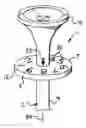
FIG. 1 is a fragmentary perspective view of a disc embodiment of a golf stroke counter apparatus according to the present invention.
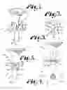
FIG. 2 is a top plan view of a disc stroke counter element employed in the apparatus shown in FIG. 1.
FIG. 3 is an enlarged fragmentary side elevational view of the apparatus shown in FIG. 1 with the disc shown in cross section to reveal details of an indexing mechanism of the apparatus.
FIG. 4 is a top plan view of a modified disc stroke counter element having a golf club cleaning tooth formed on a periphery thereof and showing a golf tee shaft in cross section.
FIG. 5 is a fragmentary side elevational view of a sleeve embodiment of the golf stroke counter apparatus according to the present invention.
FIG. 6 is a is a greatly enlarged fragmentary perspective view of a tee head embodiment of the golf stroke counter apparatus according to the present invention with a portion of a tee head broken away to illustrate details of an indexing mechanism of the apparatus.
FIG. 7 is a further enlarged cross sectional view taken on line 7-7 of FIG. 6 and illustrates details of the indexing mechanism of the apparatus.
DETAILED DESCRIPTION OF THE INVENTION
As required, detailed embodiments of the present invention are disclosed herein; however, it is to be understood that the disclosed embodiments are merely exemplary of the invention, which may be embodied in various forms. Therefore, specific structural and functional details disclosed herein are not to be interpreted as limiting, but merely as a basis for the claims and as a representative basis for teaching one skilled in the art to variously employ the present invention in virtually any appropriately detailed structure.
Referring to the drawings in more detail, the reference numeral 1 generally designates an embodiment of an improved golf stroke counter apparatus according to the present invention. Generally, the apparatus 1 includes a golf tee structure 2 and a stroke counter element 3 rotatably mounted on the tee structure 2. The stroke counter element 3 is rotated to indicate the current stroke count, as will be detailed below.
Referring to FIGS. 1-3, a disc embodiment 5 of the apparatus 1 includes the tee structure 2 and a stroke counter element 3 in the form of a stroke counter disc 7. The illustrated tee structure 2 is in the form of a conventional golf tee and includes an elongated, cylindrical tee shaft 9 which expands to a cupped tee head 10. Although not shown, a lower end of the tee shaft 9 may be pointed. The tee structure 2 may be formed of a conventional tee material, such as a wooden material or a durable plastic.
The illustrated stroke counter disc 7 is of a flat annular shape with an outer periphery 12 and a central aperture 14 formed by a circular aperture surface 15. The disc 7 has upper and lower planar surfaces 17 and 18 (FIG. 3). In the illustrated apparatus 5, stroke count numerals 20 are formed in circumferentially spaced relation on the upper surface 17 of the disc 7, while a stroke count index or index mark or pointer 22 is formed on the tee shaft 9. A given count of strokes for a golf hole is indicated by rotating the stroke counter disc 7 about a longitudinal axis 24 of the tee shaft 9 to align the stroke count index 22 with the current count of strokes. It is foreseen that the stroke count numerals 20 could, alternatively, be formed on the tee shaft 9 and the stroke index 22 on the stroke counter disc 7. The disc 7 may be formed from a material, such as a flexible polymer or the like.
The illustrated tee structure 2 has a circumferential groove 26 formed about the tee shaft 9. The aperture surface 15 of the disc 7 has an inner diameter which is less than an outer diameter of the tee shaft 9. Thus, when the disc aperture 14 is aligned with the groove 26, the disc 7 resiliently snaps into the groove 26 to retain the disc 7 in a desired position on the tee shaft 9. As retained on the shaft 9, the disc 7 is rotatable to align the stroke count numerals 20 with the stroke count index 22.
It is desirable to retain the stroke count which has been set until it needs to be advanced or reset to zero. The apparatus 1 is provided with an indexing mechanism 28 to releasably retain alignment between the stroke count index 22 and a stroke count numeral 20 until it is desired to advance or reset the stroke count. In the illustrated embodiment 5, the indexing mechanism 28 is implemented as a series of circumferentially spaced ratchet teeth 30 formed in the groove 26 in cooperation with an indexing tooth 31 extending radially inwardly from the aperture surface 15 of the disc 7. The stroke count index 22, the stroke count numerals 20, the ratchet teeth 30, and the indexing tooth 31 are cooperatively positioned and/or numbered so that the index 22 will be aligned with a numeral 20 when the indexing tooth 31 is positioned between a pair of adjacent ratchet teeth 30.
FIG. 4 illustrates a modified stroke counter disc 34 for use in the disc embodiment 5 of the apparatus 1. The disc 34 has a circular outer periphery 36 which is provided with a radially outwardly projecting cleaning tooth 38. The cleaning tooth 38 is provided for cleaning grooves of the head of a golf club (not shown) which can become encrusted with grass, mud, and the like which can alter the contact characteristics of the head with a golf ball (not shown). In other respects, the disc 34 is substantially similar to the stroke counter disc 7 and functions in a similar manner. It is foreseen that the stroke counter disc 34, as well as the disc 7, could be removed from the tee structure 2 and used as a ball position marker on a putting green.
FIG. 5 illustrates a sleeve embodiment 40 of the stroke counter apparatus 1 of the present invention. The apparatus 40 employs a tee structure 2 similar to the corresponding structure in the disc embodiment 5 and includes the tee shaft 9 and tee head 10. However, in the apparatus 40, the stroke counter element 3 is implemented as a stroke counter sleeve 42. The illustrated sleeve 42 is cylindrical and tubular and has the tee shaft 9 extending therethrough, whereby the sleeve 42 is rotatable about the axis 24 of the tee shaft 9. The illustrated sleeve 42 has a stroke count index 44 thereon, while the tee shaft 9 has stroke count numerals 46 formed circumferentially thereabout. The illustrated stroke count index 44 is an index window. The sleeve 42 is rotated to align the index window 44 with a stroke count numeral 46 to indicate a current stroke count for a golf hole. The sleeve 42 may be formed of a resilient polymer to enable it to be conveniently sleeved onto the tee shaft 9.
The tee shaft 9 may include a circumferential groove 48 formed thereabout in which a tooth 50 extending radially inwardly from the sleeve 42 rides to maintain the axial position of the sleeve along the tee shaft 9. The groove 48 may have ratchet teeth or protrusions 52 therein which are engaged by the tooth 50 to facilitate and maintain alignment of the window 44 with a stroke count numeral 46. The tooth 50 is, thus, an indexing tooth and forms an indexing mechanism 52 in cooperation with the ratchet teeth 52.
It is foreseen that the apparatus 40 could be implemented with the stroke count numerals 46 formed on the sleeve 42 and an index 44 other than the window, such as an index mark or pointer, formed on the tee shaft 9. It is also foreseen that the sleeve 42 may be formed with an outer diameter similar to that of the tee shaft 9 and received in a groove 48 having an axial height similar to that of the sleeve 42 so that the outer surface of the sleeve 42 is substantially flush with the outer surface of the tee shaft 9.
FIGS. 6 and 7 illustrate a rotating tee head embodiment 60 of the golf stroke counter apparatus 1 of the present invention. The counter apparatus 60 includes a tee structure 62 formed by a tee shaft 64 and a tee head 66 rotatably mounted on the tee shaft 64. The illustrated tee shaft 64 is elongated and cylindrical and may be conical or otherwise sharpened at a lower end (not shown). An upper end of the tee shaft 64 has a reduced diameter to form a tee shaft neck 68. The illustrated tee head 66 is flared in a conventional manner and has a cylindrical tee head bore 70 formed therein. The tee head 66 is pivotally mounted on the tee shaft 64 by insertion of the tee head neck 68 into the tee head bore 70.
An upper end of the tee shaft 64, near the neck 68, may have stroke count numerals 72 formed circumferentially thereon. The tee head 66 may have a stroke count index 74 formed thereon which extends to a lower end of the tee head 66 where it meets the main part of the tee shaft 64. The tee head 66 may be rotated about the tee shaft neck 68 to align the stroke index 74 with a stroke count numeral 72 to indicate a current stroke count. On the apparatus 60, the tee head 66, thus, functions as the stroke element 3. It is foreseen that the stroke count numerals 72 could, alternatively, be formed on the tee head 66 and the stroke count index 74 could be placed on the tee shaft 64.
The stroke counter apparatus 60 includes an indexing mechanism 76 engaged between the tee shaft neck 68 and the tee head 66 to facilitate and maintain alignment of the stroke index count 74 with a current stroke count numeral 72. The illustrated tee shaft neck 68 has a plurality of ratchet teeth 78 extending circumferentially thereabout. An indexing tooth 80 extends from an inner surface of the internal bore 70 of the tee head 66. The teeth 78 and 80 are positioned relative to the stroke count numerals 72 and the stroke count index 74 such that when the indexing tooth 80 is positioned between a pair of adjacent ratchet teeth 78, the stroke count index 74 is aligned with a stroke count numeral 72. The tee shaft neck 68 may have a retainer rim 82 (FIG. 6) extending thereabout which is engaged by the indexing tooth 80 when between adjacent ratchet teeth 78 to retain the tee head 66 on the tee shaft neck 68. It is foreseen that the ratchet teeth 78 and the retainer rim 82 could be, alternatively, formed on the inner surface of the bore 70 of the tee head 66 with the indexing tooth 80 formed on the surface of the tee shaft neck 68.
The tee shaft 64 and the tee head 66 may be formed, as by molding, of a somewhat pliable polymer to enable the head 66 to be snapped onto the tee shaft neck 68. Alternatively, the use of other materials is foreseen. Also, while the embodiments 5, 40, and 60 of the stroke counter apparatus 1 are principally configured for use as scoring devices, each embodiment has the form of a conventional golf tee. Thus, it is foreseen that the embodiments 5, 40, and 60 of the apparatus could function as conventional golf tees.
It is to be understood that while certain forms of the present invention have been described and illustrated herein, it is not to be limited to the specific forms or arrangement of parts described and shown.
Claims
1. A golf stroke scoring apparatus comprising:
(a) a golf tee member including a golf tee shaft having a tee axis extending therealong;
(b) a stroke counter element rotatably mounted on the tee shaft to enable rotation about the tee axis;
(c) a plurality of stroke count numerals positioned in circumferentially spaced relation about the tee axis on one of the tee shaft and the counter element;
(d) a stroke count index positioned on the other of the tee shaft and the counter element; and
(e) the tee shaft and the counter element being mutually rotated to align the index with a selected one of the stroke numerals to indicate a current stroke count for a golf course hole.
2. An apparatus as set forth in claim 1 and including:
(a) an indexing mechanism engaged between the stroke counter element and the tee shaft to facilitate alignment of the stroke count index with each stroke numeral.
3. An apparatus as set forth in claim 1 wherein:
(a) the stroke counter element is a disc having an aperture formed therethrough; and
(b) the disc is positioned on the tee shaft with the tee shaft extending through the aperture to enable the disc to rotate on the tee shaft about the tee axis.
4. An apparatus as set forth in claim 1 wherein:
(a) the stroke counter element is a disc having an aperture formed therethrough;
(b) a circumferential groove is formed in the tee shaft about the tee axis; and
(c) the disc is positioned on the tee shaft with the tee shaft extending through the aperture and with the disc snapped into the groove to enable the disc to rotate on the tee shaft about the tee axis.
5. An apparatus as set forth in claim 1 wherein:
(a) the stroke counter element is a disc having an aperture formed therethrough, the aperture having a radially inwardly extending indexing tooth;
(b) a circumferential groove is formed in the tee shaft about the tee axis, the groove having circumferentially spaced ratchet teeth formed therein; and
(c) the disc is positioned on the tee shaft with the tee shaft extending through the aperture and with the disc snapped into the groove to enable the disc to rotate on the tee shaft about the tee axis and the indexing tooth engages the groove between adjacent ratchet teeth to thereby facilitate the alignment of the stroke count index with each stroke numeral.
6. An apparatus as set forth in claim 1 wherein:
(a) the stroke counter element is a tubular sleeve; and
(b) the sleeve has the tee shaft extending therethrough to enable the sleeve to rotate on the tee shaft about the tee axis.
7. An apparatus as set forth in claim 1 wherein:
(a) the stroke count numerals are positioned in circumferentially spaced relation about the tee shaft;
(b) the stroke counter element is a tubular sleeve having a stroke count numeral opening formed therethrough; and
(c) the sleeve has the tee shaft extending therethrough to enable the sleeve to rotate on the tee shaft about the tee axis to enable selective alignment of the stroke count numeral opening with the stroke count numerals.
8. An apparatus as set forth in claim 1 wherein:
(a) a circumferential groove is formed in the tee shaft about the tee axis;
(b) the stroke counter element is a tubular sleeve having a sleeve bore formed therethrough;
(c) a tooth extends radially inwardly from the sleeve within the bore; and
(d) the sleeve is positioned on the tee shaft with the tooth engaging the groove to enable the sleeve to rotate on the tee shaft about the tee axis.
9. An apparatus as set forth in claim 1 wherein:
(a) a circumferential groove is formed in the tee shaft about the tee axis, the groove having circumferentially spaced ratchet teeth formed therein;
(b) the stroke counter element is a tubular sleeve having a sleeve bore formed therethrough;
(c) an indexing tooth extends radially inwardly from the sleeve within the bore; and
(d) the sleeve is positioned on the tee shaft with the tooth engaging the groove between adjacent ratchet teeth within the groove to enable the sleeve to rotate on the tee shaft about the tee axis and to thereby facilitate the alignment of the stroke count index with each stroke numeral.
10. An apparatus as set forth in claim 1 wherein:
(a) the stroke counter element is a disc having an aperture formed therethrough and an outer periphery;
(b) the disc has a golf club head cleaning tooth extending radially outward from the outer periphery of the disc; and
(c) the disc is positioned on the tee shaft with the tee shaft extending through the aperture to enable the disc to rotate on the tee shaft about the tee axis.
11. An apparatus as set forth in claim 1 wherein:
(a) the golf tee member includes a golf tee head;
(b) the tee head is rotatably engaged with the tee shaft; and
(c) the tee head forms the stroke counter element.
12. A golf stroke scoring apparatus comprising:
(a) a golf tee member including a golf tee shaft having a tee axis extending therealong;
(b) a stroke counter element rotatably mounted on the tee shaft to enable rotation about the tee axis;
(c) a plurality of stroke count numerals positioned in circumferentially spaced relation about the tee axis on one of the tee shaft and the counter element;
(d) a stroke count index positioned on the other of the tee shaft and the counter element;
(e) a circumferential groove formed in the tee shaft about the tee axis;
(f) an indexing mechanism engaged between the stroke counter element and the circumferential groove to facilitate alignment of the stroke count index with each stroke numeral; and
(g) the tee shaft and the counter element being mutually rotated in cooperation with the indexing mechanism to align the index with a selected one of the stroke numerals to indicate a current stroke count for a golf course hole.
13. An apparatus as set forth in claim 12 wherein the indexing mechanism includes:
(a) circumferentially spaced ratchet teeth formed within the circumferential groove;
(b) an indexing tooth extending radially inwardly from the stroke counter element; and
(c) the indexing tooth engaging the groove between adjacent ratchet teeth to thereby facilitate alignment of the stroke count index with each stroke numeral.
14. An apparatus as set forth in claim 12 wherein:
(a) the stroke counter element is a disc having an aperture formed therethrough; and
(b) the disc is positioned on the tee shaft within the circumferential groove with the tee shaft extending through the aperture to enable the disc to rotate on the tee shaft about the tee axis.
15. An apparatus as set forth in claim 12 wherein:
(a) the stroke counter element is a tubular sleeve; and
(b) the sleeve has the tee shaft extending therethrough to enable the sleeve to rotate on the tee shaft about the tee axis.
16. A golf stroke scoring apparatus comprising:
(a) a golf tee member including a golf tee shaft having a tee axis extending therealong;
(b) a golf tee head rotatably mounted on the tee shaft to enable rotation about the tee axis;
(c) a plurality of stroke count numerals positioned in circumferentially spaced relation about the tee axis on one of the tee shaft and the tee head;
(d) a stroke count index positioned on the other of the tee shaft and the tee head; and
(e) the tee shaft and the tee head being mutually rotated to align the index with a selected one of the stroke numerals to indicate a current stroke count for a golf course hole.
17. An apparatus as set forth in claim 16 and including:
(a) an indexing mechanism engaged between the tee head and the tee shaft to facilitate alignment of the stroke count index with each stroke numeral.
18. An apparatus as set forth in claim 16 wherein:
(a) the tee shaft has a neck with a reduced diameter at an upper end thereof;
(b) the tee head has a bore formed into a lower end thereof; and
(c) the neck is received in the bore to enable the tee neck to rotate relative to the tee shaft.
19. An apparatus as set forth in claim 16 wherein:
(a) the tee shaft has a neck with a reduced diameter at an upper end thereof;
(b) the tee head has a bore formed into a lower end thereof;
(c) the neck is received in the bore to enable the tee neck to rotate relative to the tee shaft;
(d) a plurality of radial projections spaced circumferentially about the neck;
(e) an indexing tooth projecting radially inwardly from the bore in axial alignment with the projections; and
(f) the indexing tooth being received between the projections upon relative rotation between the tee head and the tee shaft to thereby facilitate alignment of the stroke count index with each stroke numeral.
20. An apparatus as set forth in claim 16 wherein:
(a) the stroke count numerals are circumferentially spaced about the tee shaft; and
(b) the stroke count index is positioned on the tee head.
Images & Drawings included:

Sources:
- United States Patent and Trademark Office - verify current appl. status at the USPTO↗
Recent applications in this class:
- » 20250032888 2025-01-30
MECHANICAL PICKLEBALL SCOREKEEPER - » 20240390768 2024-11-28
Scorecard holder, and method of making and using same - » 20240299831 2024-09-12
SPORTS PADDLE INCLUDING SCOREKEEPING DEVICE - » 20240149140 2024-05-09
WEARABLE MULTI-SPORT SCOREKEEPING AND COUNTING DEVICE - » 20240149139 2024-05-09
SCORECARD WITH WRITING INSTRUMENT HOLDER - » 20230330508 2023-10-19
APPARATUS, METHOD, AND SYSTEM FOR TRACKING THE GAME SCORE AND SERVICE IN PICKLEBALL - » 20230241484 2023-08-03
WEARABLE COUNTING AND SCORE KEEPING APPARATUS - » 20230201698 2023-06-29
BAG TOSS GAME BOARD WITH SCORE TRACKING - » 20220347550 2022-11-03
Scoreboard for platform tennis - » 20220105419 2022-04-07
Scorekeeping Apparatus