Device for electrically connecting power distribution plates and electrical power distribution system provided with such a connection device
US20180062358A1
2018-03-01
15/638,079
2017-06-29
✅ Patent granted
US 10,693,281 B2
2020-06-23
-
-
Anatoly Vortman
Christensen O'Connor Johnson Kindness PLLC
2037-06-29
Abstract:
A device for electrically connecting power distribution plates, comprises a connector fastened to one end of a first plate and comprising power contacts for a second plate. The connector comprises a pair of separate electrical connection parts which together electrically connect two power busbars of the first plate to two power busbars of the second plate and each includes a base for electrically connecting and mechanically fastening the part to a power busbar of the first plate and a power contact branch extending from the base and intended to interact with a power busbar of the second plate.
Assignee:
- ZODIAC AERO ELECTRIC 44 🇫🇷 Montreuil, France
Applicant:
Interested in similar patents?
Get notified when new applications in this technology area are published.
Classification:
H01R12/7088 » CPC further
Structural associations of a plurality of mutually-insulated electrical connecting elements, specially adapted for printed circuits, e.g. printed circuit boards [PCBs], flat or ribbon cables, or like generally planar structures, e.g. terminal strips, terminal blocks; Coupling devices specially adapted for printed circuits, flat or ribbon cables, or like generally planar structures; Terminals specially adapted for contact with, or insertion into, printed circuits, flat or ribbon cables, or like generally planar structures; Coupling devices Arrangements for power supply
H01R12/732 » CPC further
Structural associations of a plurality of mutually-insulated electrical connecting elements, specially adapted for printed circuits, e.g. printed circuit boards [PCBs], flat or ribbon cables, or like generally planar structures, e.g. terminal strips, terminal blocks; Coupling devices specially adapted for printed circuits, flat or ribbon cables, or like generally planar structures; Terminals specially adapted for contact with, or insertion into, printed circuits, flat or ribbon cables, or like generally planar structures; Coupling devices for rigid printing circuits or like structures coupling with the edge of the rigid printed circuits or like structures connecting to other rigid printed circuits or like structures Printed circuits being in the same plane
B64D2221/00 » CPC further
Electric power distribution systems onboard aircraft
H01R12/73 IPC
Structural associations of a plurality of mutually-insulated electrical connecting elements, specially adapted for printed circuits, e.g. printed circuit boards [PCBs], flat or ribbon cables, or like generally planar structures, e.g. terminal strips, terminal blocks; Coupling devices specially adapted for printed circuits, flat or ribbon cables, or like generally planar structures; Terminals specially adapted for contact with, or insertion into, printed circuits, flat or ribbon cables, or like generally planar structures; Coupling devices for rigid printing circuits or like structures coupling with the edge of the rigid printed circuits or like structures connecting to other rigid printed circuits or like structures
H01R25/16 IPC
Coupling parts adapted for simultaneous co-operation with two or more identical counterparts, e.g. for distributing energy to two or more circuits Rails or bus-bars provided with a plurality of discrete connecting locations for counterparts
H05K7/1457 » CPC further
Constructional details common to different types of electric apparatus; Mounting supporting structure in casing or on frame or rack; Back panels or connecting means therefor; Terminals; Coding means to avoid wrong insertion Power distribution arrangements
H05K7/1457 » CPC further
Constructional details common to different types of electric apparatus; Mounting supporting structure in casing or on frame or rack; Back panels or connecting means therefor; Terminals; Coding means to avoid wrong insertion Power distribution arrangements
H02B1/48 » CPC further
Frameworks, boards, panels, desks, casings; Details of substations or switching arrangements; Casings; Parts thereof or accessories therefor; Boxes; Parts thereof or accessories therefor Mounting of devices therein
H02J4/00 » CPC further
Circuit arrangements for mains or distribution networks not specified as ac or dc
H01R25/164 » CPC further
Coupling parts adapted for simultaneous co-operation with two or more identical counterparts, e.g. for distributing energy to two or more circuits; Rails or bus-bars provided with a plurality of discrete connecting locations for counterparts Connecting locations formed by flush mounted apparatus
H01R2201/26 » CPC further
Connectors or connections adapted for particular applications for vehicles
H02B1/20 » CPC main
Frameworks, boards, panels, desks, casings; Details of substations or switching arrangements Bus-bar or other wiring layouts, e.g. in cubicles, in switchyards
H05K7/14 IPC
Constructional details common to different types of electric apparatus Mounting supporting structure in casing or on frame or rack
H05K7/14 IPC
Constructional details common to different types of electric apparatus Mounting supporting structure in casing or on frame or rack
H01R12/70 IPC
Structural associations of a plurality of mutually-insulated electrical connecting elements, specially adapted for printed circuits, e.g. printed circuit boards [PCBs], flat or ribbon cables, or like generally planar structures, e.g. terminal strips, terminal blocks; Coupling devices specially adapted for printed circuits, flat or ribbon cables, or like generally planar structures; Terminals specially adapted for contact with, or insertion into, printed circuits, flat or ribbon cables, or like generally planar structures Coupling devices
H02J1/10 » CPC further
Circuit arrangements for dc mains or dc distribution networks Parallel operation of dc sources
B64D41/00 » CPC further
Power installations for auxiliary purposes
F16B39/10 » CPC further
Locking of screws, bolts or nuts in which the locking takes place after screwing down by a plate, or ring immovable with regard to the bolt or object
Description
The invention relates, in general, to electrical power distribution systems, especially for aircraft and, in particular, electrical power distribution systems provided with power distribution plates.
It is known that an electrical power distribution system within an aircraft has a pyramidal structure.
The electrical power is first of all generated using part of the power supplied by the engines of the aircraft to drive electrical power generators. The electrical power generated is delivered to distribution cabinets, also referred to as distribution “cores”, in order to be subsequently redistributed either to loads or to secondary distribution boxes, at different amperages.
Power distribution plates are used to carry currents within the power distribution system, in particular within the distribution cabinets, due to the power levels carried within the cabinet, which may reach values in the megawatt range. They generally include an insulating plate to which an electrical distribution busbar is fastened.
The distribution busbars of the power plates are conventionally connected using an electrical connection device which includes a connector that is fastened to one end of a power busbar and in which another power busbar is connected.
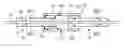
FIGS. 1 and 2 illustrate such an electrical connection device according to the prior art, being used for the electrical connection of two plates 1 and 2 each comprising an insulating support 3, 4 to which respective power distribution busbars 5 and 6 are fastened.
The busbars 5 and 6 are connected by means of a connector 7 taking the overall form of a fork, fastened by a first end 8 to one of the busbars and comprising, at its opposite end, power contact branches, such as 9, being used for the electrical connection of the other busbar 5, interposed between power contacts 10.
With reference to FIG. 2, such a connection device is used to carry currents between two busbars 5 and 6 having one and the same potential VD (arrows F).
Such a connection device is an effective means for connecting distribution plates which convey only one voltage level.
However, when it comes to conveying multiple voltage levels, the plates and their connection devices must be duplicated.
This is especially the case when two power busbars are used to convey voltages having different polarities, for example positive and negative, which has drawbacks in terms of bulk, cost and complexity of assembly.
The object of the invention is to overcome these drawbacks.
One subject of the invention, according to a first aspect, is a device for electrically connecting power distribution plates, comprising a connector fastened to one end of a first plate and comprising power contacts for a second plate.
The connector comprises a pair of separate electrical connection parts which together electrically connect two power busbars of the first plate to two power busbars of the second plate and each include, at one end, a base for electrically connecting and mechanically fastening the part to a power busbar of the first plate and a power contact branch extending from the base and intended to interact with a power busbar of the second plate.
Thus, by using a pair of electrical connection parts, it is possible to connect two power busbars having different respective potential levels simultaneously, thereby facilitating the connection of the power busbars, decreasing the number of connectors used to connect the busbars and allowing the general bulk of the power plates to be decreased.
The electrical connection device allows two dual-polarity power distribution plates to be electrically connected, or else two plates at a single potential to be electrically connected to a plate at two potentials.
According to another feature, the connection parts are made of metal, preferably of aluminium.
Advantageously, the power contacts comprise elastically deformable conductive strips fastened to the contact branches.
Stated otherwise, each contact branch comprises power contacts in the form of elastically deformable conductive strips.
Another subject of the invention, according to a second aspect, is an electrical power distribution system comprising power distribution plates and devices for electrically connecting plates each comprising a connector fastened to one end of a first plate and comprising power contacts for a second plate.
The connector comprises a pair of separate electrical connection parts which together electrically connect two power busbars of the first plate to two power busbars of the second plate and each include a base for electrically connecting and mechanically fastening the part to a power busbar of the first plate and a power contact branch extending from the base and intended to interact with a power busbar of the second plate.
In one embodiment, the distribution plates each comprise an insulating plate and two power busbars having different polarities provided on two mutually opposite faces of the plate.
Thus, the connection parts are advantageously fastened on either side of the first plate.
The power busbars may be bonded or screwed to the insulating plate.
Regarding the connection parts, they may be fastened to the first plate by means of screwing or crimping or fastened by force thereto by means of pads.
The electrical connection device allows two dual-polarity power distribution plates to be electrically connected, or else two plates at a single potential to be electrically connected to a plate at two potentials.
Other objects, features and advantages of the invention will become apparent on reading the following description, which is given solely by way of non-limiting example and with reference to the appended drawings, in which:
FIGS. 1 and 2, of which mention has already been made, illustrate the arrangement of a device for electrically connecting power distribution plates according to the prior art;
FIGS. 3 and 4 illustrate the structure of an electrical connection device according to one embodiment of the invention; and
FIG. 5 illustrates another mode of implementation of an electrical connection device according to the invention.
FIGS. 3 and 4 illustrate one exemplary embodiment of a device for electrically connecting power distribution plates according to one embodiment of the invention.
The electrical connection device, denoted by the general numerical reference 12, is intended to provide the electrical connection of two dual-polarity power distribution plates 13 and 14.
Specifically, as may be seen, each power distribution plate 13 and 14 includes an insulating plate, such as 15, for example made of polychlorobiphenyl (PCB) and two power busbars 16 and 17 fastened to, for example by bonding or screwing, or else mounted by force on, two mutually opposite faces of the insulating plate 15.
These two busbars are intended to be set to two different potential levels VD1 and VD2. They are, for example, made of aluminium or of copper.
Regarding the electrical connection device, the latter comprises a connector consisting of a pair of connection parts 18 and 19 each comprising, at one end, a base, such as 20, for electrically connecting and mechanically fastening the power busbars of one of the plates 14 to a contact branch 21 extending from the base 20 in the direction of the other plate.
Stated otherwise, the two connection parts 18 and 19 each provide the electrical connection of a busbar of one of the plates to a busbar of the other plate. The busbars are thus fastened, by one of their ends, on either side of the first distribution plate 14 and are electrically connected, by their other end, to the other plate 13.
The connection parts may be made of metal, for example of aluminium or of copper.
As may be seen, electrical contacts produced in the form of elastically deformable metal strips, such as 22, or in the form of electrical joints or plungers interposed between the branches 21 and the power busbars 16 and 17 are advantageously used. The strips are shaped so as to provide close contact with the power busbars that is sufficient to withstand the vibratory environment to which the connection devices are subjected, while allowing ease of connection.
These electrical contacts are for example fastened to the branches 21, for example by welding or by screwed clip-fastening.
The connection parts 18 and 19 may be fastened to the plate 14 by any suitable means.
In one embodiment, this fastening is achieved by brazing, screwing or crimping or using a pin riveted to the connection parts and to the distribution plates.
They may also be force-fitted to the first plate by providing pads on the connection parts.
Advantageously, two fastening points are used, for example two pins that are riveted in order to prevent any rotation of the connection device with respect to the distribution plate to which it is fastened.
Of course, the connection parts may be formed as a single part with the power busbars without departing from the scope of the invention.
As will be appreciated, the invention that has just been described allows the simultaneous electrical connection of two power busbars using a single electrical connection device, thereby optimizing the volume used and decreasing manufacturing costs.
An electrical connection device according to the invention does indeed allow currents to be carried between the distribution plate busbars at two different potentials VD1 and VD2 (arrows F1 and F2).
It has also been shown that the electrical connection device according to the invention allows improved insertion of the power plates insofar as only one connector is necessary to connect the power busbars.
Lastly, the superposition of the two polarities in a non-inductive network makes it possible to limit line inductances.
Lastly, the invention that has just been disclosed is not limited to the embodiment described.
Specifically, in the embodiment described with reference to FIGS. 3 and 4, the two connection parts are fastened to the first plate which includes two power busbars 16 and 17 fastened to two mutually opposite faces of an insulating plate 15.
In the embodiment of FIG. 5, in which elements identical to those described above bear the same numerical references, the connection device, which includes two connection parts 18 and 19 each having a base 20 and a contact branch 21 provided with its metal strip 22, provides the electrical connection of two plates 14 and 14′ at a single potential to a plate 13 at two potentials.
The plate 13 at two potentials, which comprises the insulating plate and the two power busbars 16 and 17, is connected to the two contact branches 21, as described above with reference to FIGS. 3 and 4.
The plates at a single potential each have a single power busbar, such as 23, fastened to a single insulating plate, such as 24.
The base 20 is thus provided on the side of the connection part facing the power busbar to which it is fastened.
Claims
1. A device for electrically connecting power distribution plates, comprising a connector fastened to one end of a first plate and comprising power contacts for a second plate, wherein the connector comprises a pair of separate electrical connection parts which together electrically connect two power busbars of the first plate to two power busbars of the second plate and each includes a base for electrically connecting and mechanically fastening the part to a power busbar of the first plate and a power contact branch extending from the base and intended to interact with a power busbar of the second plate.
2. The device according to claim 1, in which the connection parts are made of metal.
3. The device according to claim 1, in which the power contacts comprise elastically deformable conductive strips.
4. The device according to claim 3, in which the strips are fastened to the contact branches.
5. An electrical power distribution system comprising two power distribution plates each comprising an insulating plate and two power busbars provided on two mutually opposite faces of said plate and a device for electrically connecting the plates according to claim 1.
6. The system according to claim 5, in which the two power busbars have different polarities.
7. The system according to claim 5, in which the connection parts are fastened on either side of the first plate.
8. The system according to claim 5, in which the power busbars are bonded or screwed to the insulating plate.
9. The system according to claim 5, in which the connection parts are fastened to the first plate by means of screwing or crimping.
10. The system according to claim 5, in which the connection parts are fastened by force to the first plate by means of pads.
11. An electrical power distribution system comprising a first dual-polarity power distribution plate and two second and third power distribution plates at a single potential, the first plate comprising an insulating plate and two power busbars provided on two mutually opposite faces of said plate and each of the second and third power distribution plates each comprising an insulating plate and a single power busbar, fastened to the corresponding insulating plate, wherein the electrical power distribution system comprises a connection device which electrically connects the two plates at a single potential to the plate at two potentials and comprises two separate connection parts each including a base for electrically connecting and mechanically fastening the part to a power busbar of one of the plates at a single potential and a contact branch provided with electrical contacts and extending from the base and intended to interact with a power busbar of the plate at two potentials.
Images & Drawings included:


Sources:
- United States Patent and Trademark Office - verify current appl. status at the USPTO↗
Similar patent applications:
Recent applications in this class:
- » 20250286352 2025-09-11
ELECTRICAL DISTRIBUTION SYSTEM AND METHOD - » 20250279634 2025-09-04
Expandable Panelboard Bus Assemblies and Methods of Assembling Same - » 20250260213 2025-08-14
BUSBAR ASSEMBLY AND METHOD OF MAKING - » 20250253625 2025-08-07
HIGH-VOLTAGE AND HIGH-CURRENT LAMINATED BUS LINE AND PREPARATION METHOD THEREOF - » 20250219362 2025-07-03
SHORT CIRCUIT MITIGATION SYSTEM AND METHOD FOR HIGH VOLTAGE DISTRIBUTION SYSTEM - » 20250183629 2025-06-05
BUS BARS FOR PRINTED STRUCTURAL ELECTRIC BATTERY MODULES - » 20250118949 2025-04-10
HIGH DENSITY POWER DISTRIBUTION SYSTEM WITH INTEGRATED BUSWAY, SMART TAP-OFF BOX AND COMPACT RACK POWER DISTRIBUTION UNITS - » 20250023333 2025-01-16
POWER SUPPLY MODULE - » 20240372338 2024-11-07
VOLTAGE CONTROLLING APPARATUS AND METHODS OF CALIBRATING A DEVICE - » 20240356313 2024-10-24
ELECTRICAL DISTRIBUTION BOX
Recent applications for this Assignee:
- » 20200272194 2020-08-27
Control device for a human-machine interface, comprising electroactive elements - » 20200006738 2020-01-02
Electrically and thermally connecting device for batteries and pieces of electrical distribution equipment of an aircraft - » 20190393774 2019-12-26
Device for transforming and for rectifying polyphase voltage - » 20190393575 2019-12-26
BATTERY COOLING AND HEATING DEVICE AND BATTERY INCORPORATING SUCH A DEVICE - » 20190241279 2019-08-08
Multifunctional aircraft landing light with static function switching - » 20190032879 2019-01-31
Lighting system for an aircraft - » 20190006852 2019-01-03
ELECTRICAL POWER DISTRIBUTION BOX FOR ONBOARD NETWORK OF AN AIRCRAFT AND CORRESPONDING ELECTRICAL POWER SUPPLY SYSTEM - » 20180328972 2018-11-15
Device and method for detecting an electrical load - » 20180316162 2018-11-01
Device for electrically connecting power distribution plates and electrical power distribution system provided with such a connection device - » 20180286615 2018-10-04
Switching element for electrical energy distribution board and electrical energy distribution box fitted with such a switching element